SINUMERIK 840D sl. Service - Safety Integrated. Manual (2020) - page 23
Control of the safety functions
6.7 Motion monitoring without selection
Differences
Differences in the response of the functions to the versions with control via PROFIsafe/
terminals are described in the sections for commissioning the individual functions:
● "Safely-Limited Speed (SLS) (Page 118)"
● "Safe Direction (SDI) (Page 134)"
Overview of important parameters (see SINAMICS S120/S150 List Manual)
● p9501.0
SI Motion enable safety functions (Control Unit)
● p9512
Select SI Motion safety functions without selection (CU)
● p9601
SI enable functions integrated in the drive (Control Unit)
Safety Integrated
256
Function Manual, 06/2020, 6SL3097-5AR00-0BP3

Control of the safety functions
6.8 Safety Info Channel and Safety Control Channel
6.8
Safety Info Channel and Safety Control Channel
6.8.1
Safety Info Channel (SIC)
The Safety Info Channel (SIC) enables Safety Integrated functionality status information of the
drive (S_ZSW1B, S_ZSW2B, S_ZSW3B, and S_V_LIMIT_B) to be transmitted to the higher-
level controller.
6.8.2
Safety Control Channel (SCC)
Using the Safety Control Channel (SCC), control information (S_STW1B and S_STW3B) can
be sent from the higher-level control to the Safety functions of the drive.
6.8.3
Possible telegram configuration (700, 701)
The predefined PROFIdrive telegrams 700 and 701 are available for the transfer of the SIC and
the SCC:
Telegram 700
The predefined PROFIdrive telegram 700 is available for the transfer of the SIC:
Table 6-21
Structure of telegram 700
Receive data
Send data
Parameter
PZD1
-
S_ZSW1B
r9734
PZD2
-
S_V_LIMIT_B
r9733[2]
PZD3
-
You will find further information on communication via PROFIdrive in the Manual "SINAMICS
S120 Communications Function Manual," Chapter "Communication according to PROFIdrive."
Telegram 701
The predefined PROFIdrive telegram 701 is available for the transfer of the SIC and the SCC:
Table 6-22
Structure of telegram 701
Receive data
Parameter
Send data
Parameter
PZD1
S_STW1B
p10250
S_ZSW1B
r9734
PZD2
S_STW3B
p10235
S_ZSW2B
r9743
PZD3
-
-
S_V_LIMIT_B
r9733[2]
PZD4
-
-
PZD5
-
-
S_ZSW3B
r10234
Safety Integrated
Function Manual, 06/2020, 6SL3097-5AR00-0BP3
257
Control of the safety functions
6.8 Safety Info Channel and Safety Control Channel
Note
Update of the send data
The send data S_ZSW2B and S_ZSW3B are only updated if the Safety Integrated Extended/
Advanced Functions are enabled.
You will find further information on communication via PROFIdrive in the Manual
"SINAMICS S120 Communications Function Manual," Chapter "Communication according to
PROFIdrive."
Safety Integrated
258
Function Manual, 06/2020, 6SL3097-5AR00-0BP3
Control of the safety functions
6.8 Safety Info Channel and Safety Control Channel
6.8.4
Configuring
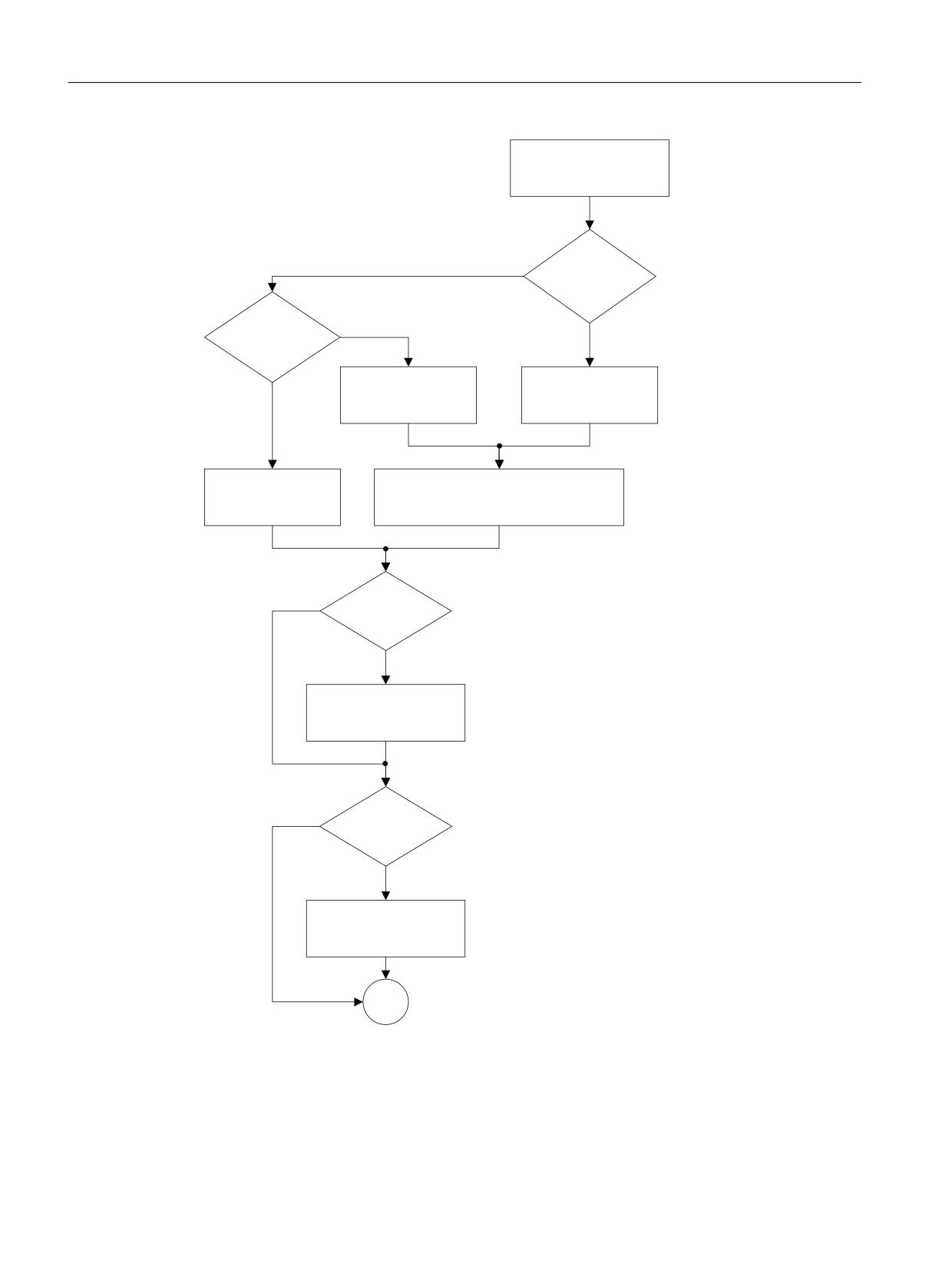
Configuration principle (diagram)
The following diagram shows the principle when configuring for telegrams 700 and 701:
Safety Integrated
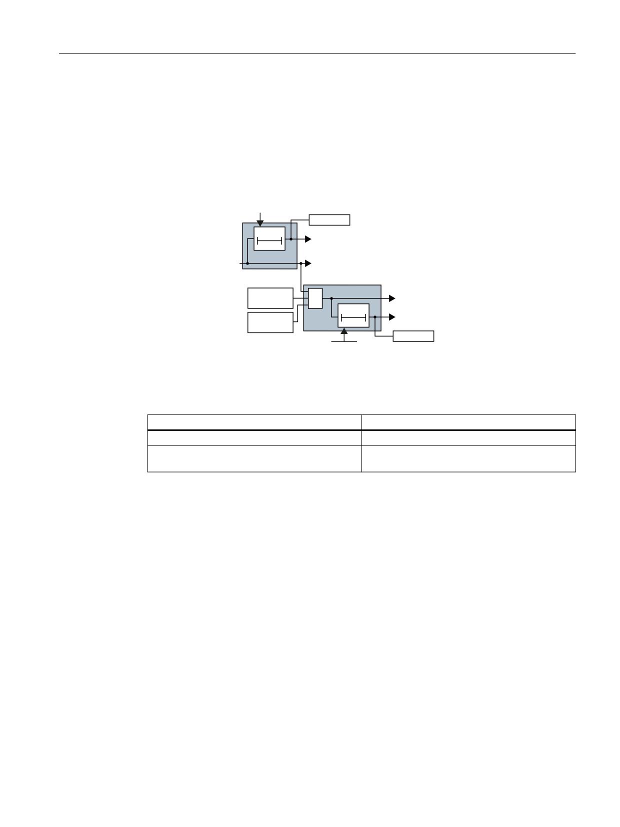
Function Manual, 06/2020, 6SL3097-5AR00-0BP3
259
Control of the safety functions
6.8 Safety Info Channel and Safety Control Channel
7HOHJUDP FRQILJXUDWLRQ
6WDQGDUG
<HV
WHOHJUDP 67'
UHTXLUHG"
)UHH %,&2
<HV
1R
LQWHUFRQQHFWLRQ
UHTXLUHG"
1R
S
S
S
S
67'
S
5HVHUYHG ZRUGV UHFHLYH
S
S
67'
S
5HVHUYHG ZRUGV WUDQVPLW
6,& 6&&
1R
UHTXLUHG"
<HV
6HW 6,& 6&&
S
1R
S
"
<HV
,QWHUFRQQHFW IUHH
%,&2V
Figure 6-10
Telegram configuration procedure
Safety Integrated
260
Function Manual, 06/2020, 6SL3097-5AR00-0BP3
Control of the safety functions
6.8 Safety Info Channel and Safety Control Channel
Configuration principle (detail)
● Parameter p2070 is used to define at which location (after how many words) the SCC starts
in receive words r2050/r2060.
● Parameter p2071 is used to define at which location (after how many words) the SIC starts
in send words p2051/p2061.
● If, using p0922 = 999 and p2079 = x, a fixed telegram is to be parameterized with PZD
extension, then you can appropriately adapt p2070 and p2071.
● For p0922 = p2079 = x, p2070 and p2071 are locked to prevent changes being made.
● When writing to parameter p0922 or p2079, parameters p2070 and p2071 are appropriately
preassigned (with the length of the standard telegram). All BICO interconnections in
r2050[...]/r2060[...] and p2051[...]/p2061[...] are deleted and reassigned to telegram x. In so
doing, p60122 is also set = 999.
● When changing from a fixed telegram (p0922 = p2079 = x) to a free telegram (p0922 = 999),
p2070 and p2071 remain unchanged, however they are released so that they can be
changed. The value of p60122 is kept.
● If p10235 and p10250 are manually changed, fault F01786 is output without any drive
response. This fault can be acknowledged by the standard message acknowledgment.
Note
Effects in r2050[...]/r2060[...] and p2051[...]/p2061[...] when changes are made to p2070,
p2071 and p60122
● If you change p2070 and p2071, all BICO interconnections in r2050[...]/r2060[...] and
p2051[...]/p2061[...] will be deleted (starting with the end of the currently set standard
telegram). In so doing, p60122 is also set = 999.
● If you change p60122 to a value ≠ 999, then (starting with the indices set in p2070 or p2071)
all BICO interconnections are deleted in r2050[...]/r2060[...] and p2051[...]/p2061[...] and
the new telegram set for SIC/SCC.
Safety Integrated
Function Manual, 06/2020, 6SL3097-5AR00-0BP3
261
Control of the safety functions
6.8 Safety Info Channel and Safety Control Channel
6.8.5
Applications
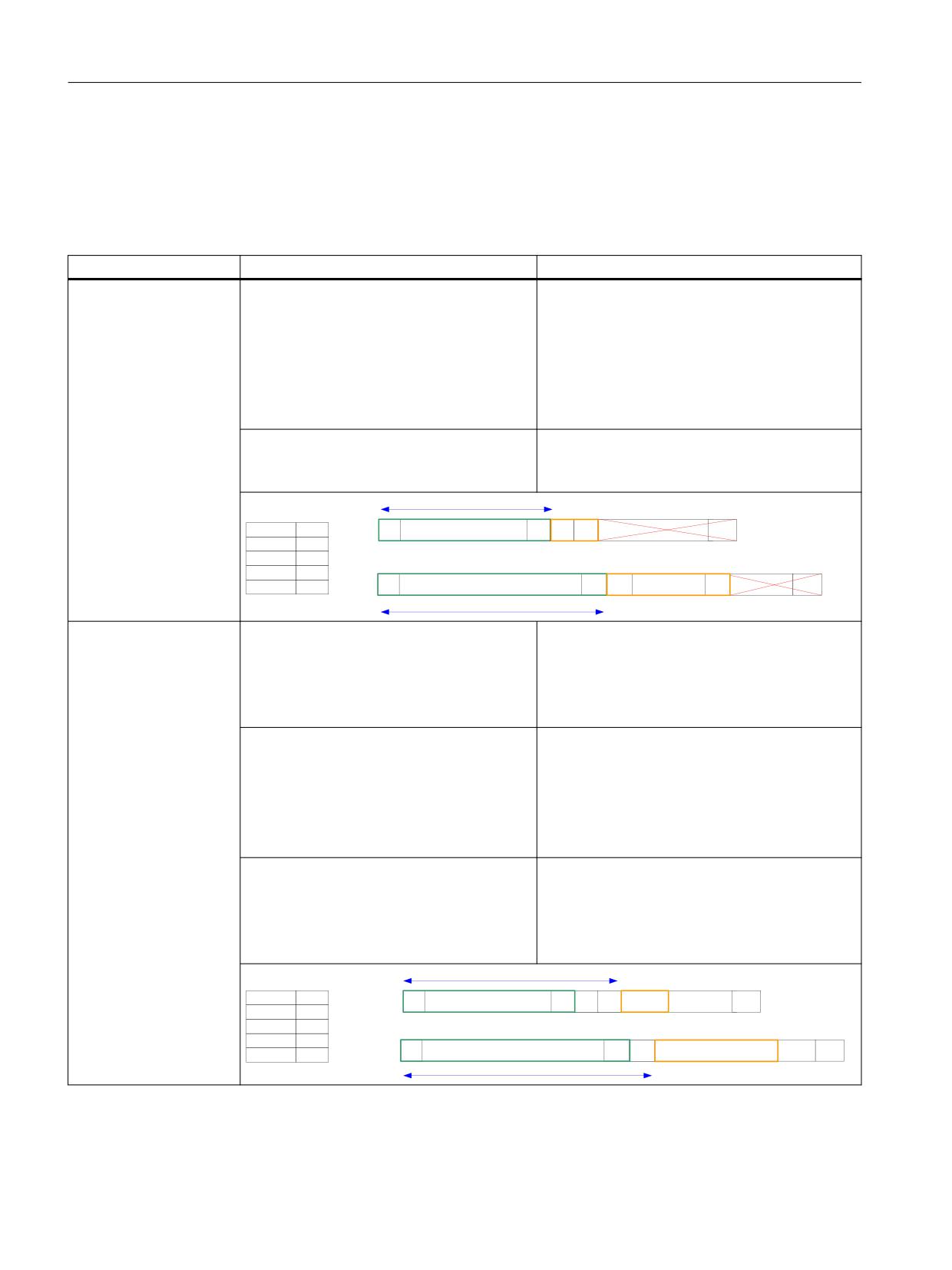
You can attach the telegrams 700 and 701 as an extension to your telegram. You can only
select one of the two telegrams.
To do this, proceed as follows:
Application
Action by the user
Effect
Standard telegram + SIC/
●
Specify standard telegram; e.g. p0922 =
● p2079 = p0922 = 106
SCC
106
● r2050 and p2051 are appropriately preas-
signed and completely locked so that changes
cannot be made.
● In p2070 and p2071, the number of transmit/
receive words are occupied and cannot be
changed (e.g: p2070 = 11 and p2071 = 15).
●
Select SIC/SCC; e.g. p60122 = 701
● The telegram extension for SCC/SIC is direct-
ly attached to the standard telegram in r2050
and p2051.
S
S
U
>@
> @
7OJ
>
@
>
@
>
@
>PD[@
(PSIDQJHQ
S
7OJ
S
S
S
>@
> @
7OJ
>
@
>
@
7OJ
>
@
>PD[@
S
6HQGHQ
S
Standard telegram + free
●
Define standard telegrams with possible
● r2050 and p2051 are appropriately preas-
telegram configuration
telegram extension; e.g. p0922 = 999 and
signed. Areas that are not preassigned, can
with BICO + SIC/SCC
p2079 = 106
be freely interconnected.
● p2070 = 11, p2071 = 15 are preassigned cor-
responding to p0922 and cannot be changed.
●
Reserve space for the telegram extension
● Words r2050[11...12] and p2051[15] are re-
with free BICO wiring, e.g. 2 words in the
served for the telegram extension and can be
receive direction and 1 word in the send
freely interconnected.
direction:
- p2070 = 11 + 2 = 13
– p2071 = 15 + 1 = 16
●
Select SIC/SCC; e.g. p60122 = 701
● The telegram extension for SIC/SCC is inser-
ted from r2050[13…] and p2051[16…].
● In r2050 and p2051, the words for SIC/SCC
are preassigned accordingly and locked. The
other words can be freely connected.
S
S
U
>@
> @
7OJ
>
@
>
@
>
@
7OJ
>PD[@
S
(PSIDQJHQ
S
S
S
>@
> @
7OJ
>
@
>
@
7OJ
>PD[@
S
6HQGHQ
S
Safety Integrated
262
Function Manual, 06/2020, 6SL3097-5AR00-0BP3

Control of the safety functions
6.8 Safety Info Channel and Safety Control Channel
Application
Action by the user
Effect
Changing the standard
● Specify a new telegram; e.g. p0922 = 105
● r2050 and p2051 are deleted and re-assigned
telegram (without free
accordingly.
telegram configuration)
● Select SIC/SCC; e.g. p60122 = 701
● The telegram extension for SCC is added after
the standard telegram.
● r2050 and p2051 are preassigned correspond-
ing to p0922 and SIC/SCC are completely
locked so that they cannot be changed.
Changing the standard
● Change standard telegram (see above)
-
telegram (with free tele-
● Now continue as described in the "Stand-
gram configuration)
ard telegram + free telegram configura-
tion with BICO + SIC/SCC"
Change of the SIC/SCC
● Change SIC/SCC; now, e.g. p60122 =
● Starting with the indices set in p2070 or
telegram
700
p2071, all BICO interconnections are deleted
in r2050[...] and p2051[...].
● The telegram extension for SIC is inserted into
parameter p2071 according to p2051.
Adding further "Free tele-
● Change the values in p2070 or p2071.
● When changing from a fixed telegram (p0922
gram configuration with
= p2079 = x) to a free telegram (p0922 = 999),
BICO" words
p2070 and p2071 remain unchanged, howev-
er they are released so that they can be
changed. The value of p60122 is kept.
● Select SIC/SCC; e.g. p60122 = 701
● SIC/SCC is reconfigured.
● Now specify the new free telegram con-
-
figuration (see above).
Note
Parameter interdependencies
● Values for p2070 or p2071, which fall below the length of the standard telegram, will be
rejected and cannot be entered.
● Write access in p60122 is rejected if excessively high values are set in p2070 or p2071 so
that attaching a SCC/SIC telegram would mean that the maximum permissible PZD lengths
would be exceeded.
Safety Integrated
Function Manual, 06/2020, 6SL3097-5AR00-0BP3
263

Control of the safety functions
6.8 Safety Info Channel and Safety Control Channel
6.8.6
Send data for SIC and SCC
S_ZSW1B
SI Motion Safety Info Channel status word
Table 6-23
Description S_ZSW1B
Bit
Meaning
Remarks
Parameter
0
STO active
1
STO active
r9734.0
0
STO not active
1
SS1 active
1
SS1 active
r9734.1
0
SS1 not active
2
SS2 active
1
SS2 active
r9734.2
0
SS2 not active
3
SOS active
1
SOS active
r9734.3
0
SOS not active
4
SLS active
1
SLS active
r9734.4
0
SLS not active
5
SOS selected
1
SOS selected
r9734.5
0
SOS deselected
6
SLS selected
1
SLS selected
r9734.6
0
SLS deselected
7
Internal event
1
Internal event
r9734.7
0
No internal event
8
SLA active
1
SLA active
r9734.8
0
SLA not active
9
Active SLS level bit 0
-
Display of the speed limit for SLS (2 bits)
r9734.9
10
Active SLS level bit 1
-
r9734.10
11
Reserved
-
-
-
12
SDI positive selected
1
SDI positive selected
r9734.12
0
SDI positive deselected
13
SDI negative selected
1
SDI negative selected
r9734.13
0
SDI negative deselected
14
ESR retract requested
1
ESR retract requested
r9734.14
0
ESR retract not requested
15
Safety message active
1
Safety message active
r9734.15
0
No safety message active
Safety Integrated
264
Function Manual, 06/2020, 6SL3097-5AR00-0BP3

Control of the safety functions
6.8 Safety Info Channel and Safety Control Channel
S_ZSW2B
Safety Info Channel status word 2
Table 6-24
Description of S_ZSW2B
Bit
Meaning
Remarks
Parameter
0...3
Reserved
-
-
-
4
SLP selected position range
1
SLP area 2 selected
r9743.4
0
SLP area 1 selected
5, 6
Reserved
-
-
-
7
SLP selected and user agreement
1
SLP selected and user agreement set
r9743.7
0
SLP selected or user agreement not set
8
SDI positive
1
SDI positive selected
r9743.8
0
SDI positive deselected
9
SDI negative
1
SDI negative selected
r9743.9
0
SDI negative deselected
10, 11
Reserved
-
-
-
12
Test stop active
1
Test stop active
r9743.12
0
Test stop not active
13
Test stop required
1
Test stop required
r9743.13
0
Test stop not required
14
Reference position required
1
Reference position required
r9743.14
0
Reference position not required
15
Reference trigger command identified
1
Reference trigger command identified or refer-
r9743.15
or reference position valid
ence position valid
0
No reference trigger command identified or refer-
ence position invalid
Safety Integrated
Function Manual, 06/2020, 6SL3097-5AR00-0BP3
265

Control of the safety functions
6.8 Safety Info Channel and Safety Control Channel
S_ZSW3B
Safety Info Channel status word 3
Table 6-25
Description of S_ZSW3B
Bit
Meaning
Remarks
Parameter
0
Brake test
1
Brake test selected
r10234.0
0
Brake test deselected
1
Setpoint input, drive/external1)
1
Setpoint specification for the drive
r10234.1
0
Setpoint specification, external (controller)
2
Active brake
1
Test brake 2 active
r10234.2
0
Test brake 1 active
3
Brake test active
1
Test active
r10234.3
0
Test inactive
4
Brake test result
1
Test successful
r10234.4
0
Test error
5
Brake test completed
1
Test run
r10234.5
0
Test incomplete
6
External brake request
1
Close brake
r10234.6
0
Open brake
7
Current load sign
1
Negative sign
r10234.7
0
Positive sign
8...10
Reserved
-
-
-
11
SS2E
1
SS2E active
r10234.11
0
SS2E not active
12
SS2ESR
1
SS2ESR active
r10234.12
0
SS2ESR not active
13
Reserved
-
-
-
14
Acceptance test SLP (SE) selected
1
Acceptance test SLP (SE) selected
r10234.14
0
Acceptance test SLP (SE) deselected
15
Acceptance test mode selected
1
Acceptance test mode selected
r10234.15
0
Acceptance test mode deselected
1)
Setpoint input for the drive: The speed setpoint is entered by the function SBT.
External setpoint input (open-loop control): The "normal" speed setpoint is effective.
S_V_LIMIT_B
SLS speed limit with 32-bit resolution and sign bit.
● The SLS speed limit is available in r9733[2].
● The SLS speed limit is standardized via p2000.
S_V_LIMIT_B = 4000 0000 hex ≐ speed in p2000
Safety Integrated
266
Function Manual, 06/2020, 6SL3097-5AR00-0BP3

Control of the safety functions
6.8 Safety Info Channel and Safety Control Channel
6.8.7
Receive data for SCC
S_STW1B
Safety Control Channel control word 1
Table 6-26
Description of S_STW1B
Bit
Meaning
Remarks
Parameter
0...7
Reserved
-
-
-
8
Extended/Advanced Functions forced
1
Extended/Advanced Functions forced checking
r10251.8
checking procedure (test stop)
procedure (test stop)
0
Extended/Advanced Functions forced checking
procedure (test stop)
9...12
Reserved
-
-
-
13
Close brake from control
1
"Close brake from control" selected
r10251.13
0
"Close brake from control" deselected
14, 15
Reserved
-
-
-
S_STW3B
Safety Control Channel control word 3
Table 6-27
Description of S_STW3B
Bit
Meaning
Remarks
Parameter
0
Select brake test
1
Brake test selected
r10231.0
0
Brake test deselected
1
Start brake test
1
Start brake test requested
r10231.1
0
Start brake test not requested
2
Brake selection
1
Test brake 2 selected
r10231.2
0
Test brake 1 selected
3
Select direction of rotation
1
Negative direction selected
r10231.3
0
Positive direction selected
4
Select test sequence
1
Test sequence 2 selected
r10231.4
0
Test sequence 1 selected
5
Status of external brake
1
External brake closed
r10231.5
0
External brake open
6...15
Reserved
-
-
-
Overview of important parameters (see SINAMICS S120/S150 List Manual)
● r9733[0...2]
CO: SI Motion setpoint speed limit effective
● r9734.0...15
CO/BO: SI Safety Info Channel status word S_ZSW1B
● r9743.4...15
CO/BO: SI Safety Info Channel status word S_ZSW2B
Safety Integrated
Function Manual, 06/2020, 6SL3097-5AR00-0BP3
267
Control of the safety functions
6.8 Safety Info Channel and Safety Control Channel
● r10231
SI Motion SBT control word diagnostics
● r10234.0...15
CO/BO: SI Safety Info Channel status word S_ZSW3B
● p10235
CI: SI Safety Control Channel control word S_STW3B
● p10250
CI: SI Safety Control Channel control word S_STW1B
● r10251.8...12
CO/BO: SI Safety Control Channel control word S_STW1B diagnostics
● p60122
IF1 PROFIdrive SIC/SCC telegram selection
Safety Integrated
268
Function Manual, 06/2020, 6SL3097-5AR00-0BP3
Commissioning
7
7.1
Safety Integrated firmware versions
Firmware versions for Safety Integrated
The safety firmware installed on the Control Unit and the safety firmware installed on the Motor
Module each have separate version IDs. The parameters listed below can be used to read the
version IDs from the relevant hardware.
● Read the overall firmware version via:
- r0018 Control Unit firmware version
● The following firmware data can be read for the Basic Functions:
- r9770[0...3] SI version, drive-autonomous safety functions (Control Unit)
- r9870[0...3] SI version, drive-autonomous safety functions (Motor Module)
● The following firmware information can be read for the Extended/Advanced Functions:
- r9590[0...3] SI Motion version safety motion monitoring (Control Unit)
- r9390[0...3] SI Motion version safety motion monitoring (Motor Module)
- r9890[0...2] SI version (Sensor Module)
or
r0148[0...n] for DQI encoders
- r10090[0...3] SI TM54F version
Basic Functions and Extended/Advanced Functions
For Basic and/or Extended or Advanced Functions that have been enabled, a check is made
to see whether the parameter for the automatic firmware update is set (p7826 = 1).
This means that at each boot, the firmware version of the DRIVE-CLiQ components involved
is checked in comparison to the firmware version of the Control Unit and, if required, updated.
Otherwise, the message F01664 (SI CU: No automatic firmware update) is output.
In the acceptance test of the Safety Integrated Basic Functions, the Safety Firmware Versions
(r9770, r9870) must be read out and recorded.
In the acceptance test of the Safety Integrated Extended/Advanced Functions, the Safety
Firmware Versions of the Motor Modules (r9590, r9390), the Sensor Modules (r9890 or
r0148[0...n] for DQI encoders), and, if necessary, the Terminal Module TM54F (r10090)
participating in the safety functions must be read out and recorded.
Safety Integrated
Function Manual, 06/2020, 6SL3097-5AR00-0BP3
269

Commissioning
7.2 Parameters, checksum, version
7.2
Parameters, checksum, version
Properties of Safety Integrated parameters
The following applies to Safety Integrated parameters:
● The safety parameters are kept separate for each monitoring channel.
● During startup, checksum calculations (Cyclic Redundancy Check, CRC) are performed on
the safety parameter data and checked. The display parameters are not contained in the
CRC.
● Data storage: The parameters are stored on the non-volatile memory card.
● The safety parameterization is password-protected against accidental or unauthorized
changes.
● Factory settings for safety parameters
- The drive-specific reset of the Safety parameters to the factory setting with p3900 and
p0010 = 30, is only possible if the safety functions are not enabled (p9501 = p9601 =
p10010 = 0).
- Safety parameters can be reset to the factory setting with p0970 = 5. To do so, the Safety
Integrated password must be set. If Safety Integrated has been enabled, this can result
in error messages that require an acceptance test to be performed. Then save the
parameters and carry out a POWER ON.
- A complete reset of all parameters to the factory settings (p0976 = 1 and p0009 = 30 on
the Control Unit) is possible even when the safety functions are enabled
p9501 = p9601 = p10010 ≠ 0).
Note
You will find more detailed information on this password in Chapter "Handling the Safety
password (Page 272)."
Note
Safety parameters that are not protected
The following safety parameters are not protected by the safety password:
● p9370 SI Motion acceptance test mode (Motor Module)
● p9570 SI Motion acceptance test mode (Control Unit)
● p9533 SI Motion SLS speed setpoint limitation
● p9783 SI Motion synchronous motor current injection without encoder
Note
The password protection is only available online.
Safety Integrated
270
Function Manual, 06/2020, 6SL3097-5AR00-0BP3

Commissioning
7.2 Parameters, checksum, version
Checking the checksum
For each monitoring channel, the Safety parameters include 2 parameters for the reference
and actual checksum for the Safety parameters that have undergone a checksum check.
During commissioning, the actual checksum must be transferred to the corresponding
parameter for the reference checksum. This can be done for all checksums of a drive object at
the same time using parameter p9701 or using the corresponding Startdrive functionality.
● Basic Functions
● r9798
SI actual checksum SI parameters (Control Unit)
● p9799
SI reference checksum SI parameters (Control Unit)
● r9898
SI actual checksum SI parameters (Motor Module)
● p9899
SI reference checksum SI parameters (Motor Module)
● Extended/Advanced Functions (also contain the following checksum parameters)
● r9398[0...1]
SI Motion actual checksum SI parameters (Motor Module)
● p9399[0...1]
SI Motion reference checksum SI parameters (Motor Module)
● r9728[0...2]
SI Motion actual checksum SI parameters
● p9729[0...2]
SI Motion reference checksum SI parameters
During each ramp-up procedure, the actual checksum is calculated via the Safety parameters
and then compared with the reference checksum.
If the actual and reference checksums are different, fault F01650/F30650 or F01680/F30680 is
output.
Function diagrams (see SINAMICS S120/S150 List Manual)
●
2818
SI Extended/Advanced Functions - parameter manager
Safety Integrated
Function Manual, 06/2020, 6SL3097-5AR00-0BP3
271

Commissioning
7.3 Handling the Safety password
7.3
Handling the Safety password
The safety password protects safety parameters against maloperation. Always assign a strong
password, to enable protection.
Note
The safety password does not have the equivalent quality of a password (protection against
unauthorized access, e.g. by an attacker), but rather that of write protection (e.g. protection
against maloperation).
Note
The password protection is only available online.
Password reset
● You require a valid password to reset the password to the factory setting by resetting the
safety parameters.
● Please note that when the factory setting is reset throughout the complete device, then the
safety password is also deleted.
Details on handling the safety password
If a password is set, in commissioning mode for Safety Integrated (p0010 = 95), you cannot
change safety parameters until you have entered the valid safety password in p9761 for the
drives or p10061 for the TM54F. In addition to the specified parameters, a corresponding
functionality is available in Startdrive!
● When Safety Integrated is commissioned for the first time, the following applies:
- Default of p10061 = 0 (SI password entry TM54F)
- Default of p9761 = 0 (SI password entry drive)
This means:
You do not need to enter a safety password during the first commissioning.
● In the case of a series commissioning of Safety or in the case of spare part installation, the
following applies:
- The Safety password is retained on the memory card and in the Startdrive project.
- No safety password is required in the case of spare part installation.
Safety Integrated
272
Function Manual, 06/2020, 6SL3097-5AR00-0BP3
Commissioning
7.3 Handling the Safety password
●
Change password for the drives
- p0010 = 95 Commissioning mode.
- p9761 = Enter "old safety password".
- p9762 = Enter "new password".
- p9763 = Confirm "new password".
- p0977 = 1; "Copy from RAM to ROM"
- The new and confirmed safety password is valid immediately.
●
Change password for the TM54F
- p0010 = 95 Commissioning mode.
- p10061 = Enter "Old TM54F Safety Password" (factory setting "0")
- p10062 = Enter "new password"
- p10063 = Acknowledge "new password"
- p0977 = 1; "Copy from RAM to ROM"
- The new and acknowledged safety password is valid immediately.
●
Change password with Startdrive
- Click "Enter password" in the Startdrive secondary navigation.
- Enter the current password.
- Enter the new password.
- Enter the new password again.
- Click "Change password" to accept the new password.
Safety Integrated
Function Manual, 06/2020, 6SL3097-5AR00-0BP3
273
Commissioning
7.3 Handling the Safety password
● Reset password with Startdrive
- Click "Enter password" in the Startdrive secondary navigation.
- In the subsequent dialog, first enter the old password.
- Set the new password = 0.
- Click "Change password" to accept the new password.
- SINAMICS S120 responds with the message "Please change the password!"
- Close the message.
- In the "Change password" dialog box, then click the "Cancel" button.
- The password has now been reset to the default "0."
● If the safety password is no longer available, you can no longer change the safety
configuration. You then have the following options:
- To commission the SINAMICS S120 completely as new:
- Restore the factory settings of the entire drive (Control Unit with all connected drives/
components).
- Commission the drive unit and the drives afresh.
- Commission Safety Integrated as new.
- To load another project into the drive (without a Safety password or with a known Safety
password). This is possible without a password because this operation is the same as
complete new commissioning.
- If neither option is acceptable to you, please contact "Technical Support" (see "Training
and support (Page 17)").
Function diagrams (see SINAMICS S120/S150 List Manual)
●
2818
SI Extended/Advanced Functions - parameter manager
Overview of important parameters (see SINAMICS S120/S150 List Manual)
● p9761
SI password input
● p9762
SI password new
● p9763
SI password acknowledgment
● p10061
SI TM54F password entry
● p10062
SI TM54F password new
● p10063
SI TM54F password confirmation
Safety Integrated
274
Function Manual, 06/2020, 6SL3097-5AR00-0BP3
Commissioning
7.4 DRIVE-CLiQ rules for Safety Integrated Functions
7.4
DRIVE-CLiQ rules for Safety Integrated Functions
Note
General DRIVE-CLiQ rules
For the Safety Integrated Functions (Basic, Extended and Advanced Functions) the general
DRIVE-CLiQ rules apply as a basic principle. You will find these rules in Section "Rules for
connection with DRIVE-CLiQ" in the following manual:
References: SINAMICS S120 Drive Functions Function Manual
This specification also lists the exceptions for Safety Integrated components depending on the
firmware version.
Note
Effect of the Safety monitoring clock cycle (p9500)
If you select a value of <12 ms for the Safety monitoring clock cycle, you can operate fewer than
the specified number of maximum axes at one Control Unit if you have demanding
configurations.
Rules for Safety Integrated Basic Functions
The following rule also applies particularly for Safety Integrated Basic Functions:
● Maximum of four drives per DRIVE-CLiQ line for control via PROFIsafe
Rules for Safety Integrated Extended/Advanced Functions
The following rules are also valid particularly for the Safety Integrated Extended/Advanced
Functions:
● Maximum of 6 servo axes for default clock cycle settings (Safety monitoring clock
cycle = 12 ms; current controller cycle = 125 μs); of which a maximum of 4 servo axes are
in one DRIVE-CLiQ line
● Maximum of six vector axes for the following cycle settings (Safety monitoring cycle = 12 ms;
current controller cycle = 500 μs)
● One Double Motor Module corresponds to 2 DRIVE-CLiQ nodes.
Safety Integrated
Function Manual, 06/2020, 6SL3097-5AR00-0BP3
275

Commissioning
7.4 DRIVE-CLiQ rules for Safety Integrated Functions
● On Double Motor Modules, on the drive objects, different values for p9511 are not permitted,
even if the values in p0115[0] are different.
● You can operate a maximum of 4 Motor Modules with Safety Extended Functions on one
DRIVE-CLiQ line. The following condition applies in this regard: TIReg (current controller
sampling time) = 125 μs for all axes. In addition to the 4 Motor Modules with Safety Extended
Functions, you can also operate the following modules on a DRIVE-CLiQ line:
- A Line Module if TIReg (current controller sampling time) ≥ 250 μs
- A Motor Module if TIReg (current controller sampling time) ≥ 125 μs
- A maximum of 7 Sensor Modules or DRIVE-CLiQ encoders
Exception: You can operate a maximum of 6 Motor Modules with Safety Extended
Functions on one DRIVE-CLiQ line if the number of connected S120M or S220 modules in
the line is ≥ 3.
Rules for "U/f control (vector control)",1)
Safety functionality
Number of U/f axes
Basic Functions
12
Basic Functions via TM54F
6
Extended/Advanced Functions via PROFIsafe
11
Extended/Advanced Functions via TM54F
6
Motion monitoring without selection
122)
1)
The values specified in the table apply to Extended/Advanced Functions with and without encoder and
also for group drives connected in parallel.
2)
All axes U/f control, 500 µs, Safety Integrated with encoder
TM54F
● The TM54F connection must be established via the DRIVE-CLiQ directly at a Control Unit.
Only one TM54F Terminal Module can be assigned to each Control Unit.
● Additional DRIVE-CLiQ nodes can be operated at the TM54F, such as Sensor Modules and
Terminal Modules (excluding an additional TM54F). It is not permissible that Motor Modules
and Line Modules are connected to a TM54F.
● In the case of a CU310-2 Control Unit, it is not possible to connect the TM54F to the DRIVE-
CLiQ line of a Power Module. The TM54F can only be connected to the sole DRIVE-CLiQ
X100 socket of the Control Unit.
Safety Integrated
276
Function Manual, 06/2020, 6SL3097-5AR00-0BP3
Commissioning
7.5 Forced checking procedure (test stop)
7.5
Forced checking procedure (test stop)
To meet the requirements of the DIN EN ISO 13849-1 and IEC 61508 standards in terms of
timely fault detection, the converter must test its safety-related circuits regularly - at least once
a year - for correct functioning. The converter monitors the regular test of its safety-related
circuits that monitor the speed of the motor, and to safely interrupt the torque-generating energy
supply to the motor through the safe pulse suppression.
0RQLWRULQJ WLPH IRU ([WHQGHG
)XQFWLRQV
$
7
)RUFHG GRUPDQW HUURU GHWHFWLRQ RI WKH
([WHQGHG )XQFWLRQV UHTXLUHG
6WDUW IRUFHG GRUPDQW
6WDUW IRUFHG GRUPDQW HUURU GHWHFWLRQ RI
HUURU GHWHFWLRQ
WKH ([WHQGHG )XQFWLRQV
3RZHU 21
6WDUW IRUFHG GRUPDQW HUURU GHWHFWLRQ
ุ
5HVHW
RI WKH %DVLF )XQFWLRQV
7
)RUFHG GRUPDQW HUURU GHWHFWLRQ RI WKH
672 LV
%DVLF )XQFWLRQV UHTXLUHG
DFWLYH
$
0RQLWRULQJ WLPH IRU %DVLF
)XQFWLRQV
Figure 7-1
Monitoring the regular forced checking procedure (test stop) in the converter
Table 7-1
Monitoring the forced checking procedure (test stop)
Extended/Advanced Functions
Basic Functions
r9765 contains the remaining monitoring time.
r9660 contains the remaining monitoring time.
The converter signals that the monitoring time has
The converter signals that the monitoring time has
come to an end with alarm A01697.
come to an end with alarm A01699.
7.5.1
Setting the forced checking procedure (test stop)
Setting the forced checking procedure (test stop)
If you only use the "Basic Functions", you must take the following steps during commissioning:
1. Set monitoring time p9659 to a value to match your application.
2. Evaluate the warning A01699 in your higher-level control, e.g. r9773.31 with a digital output
or a bit in the status word of the field bus.
Safety Integrated
Function Manual, 06/2020, 6SL3097-5AR00-0BP3
277
Commissioning
7.5 Forced checking procedure (test stop)
The circuits of "Basic Functions" are part of the circuits of "Extended/Advanced Functions". If
you use the "Extended/Advanced Functions", you must take the following steps during
commissioning:
1. Set monitoring time p9559 to a value to match your application.
2. Set the monitoring time p9659 to the maximum value.
3. Evaluate alarm A01697 in your higher-level controller, for example by interconnecting the
output of the time monitoring (r9723.0) with a digital output or a bit in the status word of the
fieldbus.
7.5.2
Executing the forced checking procedure (test stop)
If the converter signals alarm A01699 or A01697, you must initiate the forced checking
procedure (test stop) at the next opportunity.
These alarms do not affect the operation of your machine. You should shut down the drive
before performing the forced checking procedure (test stop).
Note
Internal selection of STO
Controlling the forced checking procedure (test stop) causes STO to be selected internally. In
this case, drives that were previously not stopped, or that do not have a holding brake, coast
down.
Initiating the forced checking procedure (test stop)
● Extended/Advanced Functions
- You define the signal with which the converter tests its circuits for speed monitoring.
Alternatively, the test can be performed automatically every time the power supply is
switched on (POWER ON).
- To ensure that the forced checking procedure (test stop) is performed without error, it is
not permissible that STO is active.
- If you select the forced checking procedure (test stop), the converter checks the
Extended/Advanced Functions and Basic Functions circuits.
● Basic Functions
The converter checks its circuits for interruption of the torque-generating energy feed to the
motor for one of the following conditions:
- After the power supply has been connected (POWER ON).
- Each time after selecting the function STO or SS1.
- For the forced checking procedure (test stop) of the Extended Functions.
Safety Integrated
278
Function Manual, 06/2020, 6SL3097-5AR00-0BP3
Commissioning
7.5 Forced checking procedure (test stop)
Note
Additional information
● You will find detailed information on forced checking procedure (test stop), in Chapter
"General (Page 174)."
● You will find a description of the forced checking procedure (test stop) of the TM54F in
Chapter "Forced checking procedure (test stop) of the TM54F (Page 314)."
7.5.3
Examples for the instants in time that the forced checking procedure (test stop) is
performed
● When the drives are at a standstill after the system has been switched on
● When the protective door is opened
● At defined intervals (e.g. every eight hours)
● Automatically, each time the power supply voltage is switched on (POWER ON).
● In the automatic mode, time and event-dependent
Note
Test stop of a CU310-2
The pulses must be enabled when conducting a test stop at a CU310-2: Here, the drive should
be switched on with Nset = 0.
Safety Integrated
Function Manual, 06/2020, 6SL3097-5AR00-0BP3
279

Commissioning
7.6 Safety Integrated and ESR
7.6
Safety Integrated and ESR
The following table lists the options that SINAMICS Safety Integrated offers for ESR. There are
3 variants in which the converter triggers ESR:
1.
STOP E
Internal response to a limit value violation + SLS, SDI, SLP, SLA with subsequent response
2.
STOP F
Defect in a monitoring channel + programmed subsequent response with STOP B →
STOP A
3.
Communication breakdown
Cable, CPU STOP, ...
Variant
Basic Functions
Extended/Advanced Functions
ESR integra-
1
● STOP E: NOT POSSIBLE → SS1 immedi-
● STOP E (internal response to a limit value
ted in the
ately responds with STOP B
violation + SLS, SDI, SLP, SLA with sub-
drive ("inter-
sequent response)
nal" ESR)
● Is initiated when a limit value is violated, for
example
● For these functions, the following value is
monitored:
p0890[1] = r9721.15 (Safety Integrated
STOP E)
2
● STOP F (defect in a monitoring channel +
● STOP F (defect in a monitoring channel +
programmed subsequent response with
programmed subsequent response with
STOP B → STOP A)
STOP B → STOP A)
● E. g. for a discrepancy at the input terminals
● In the transition time from STOP F to
STOP B, you can request an ESR.
● Basic Functions, set r9734.14
● p0890[2] = r9723.1 (Safety Integrated
● p0890[4] = r9734.14
STOP F)
3
● Communication breakdown: NOT POSSI-
● Communication error (cable, CPU
BLE
STOP, ...)
● During the "Delay for bus failure" (p9580)
from STOP F to STOP B, you can request
an ESR.
● p0890[3] = r9723.2 (Safety Integrated com-
munication failure)
● NOTE: As p9580 delays the initiation of
STO, you must explicitly select a safety
function with delay. For this function, pa-
rameterize a STOP with delayed STO
when the bus fails (e.g. p9563 for SLS).
Safety Integrated
280
Function Manual, 06/2020, 6SL3097-5AR00-0BP3

Commissioning
7.6 Safety Integrated and ESR
Variant
Basic Functions
Extended/Advanced Functions
ESR via a
1
●
STOP E: NOT POSSIBLE → SS1 immedi-
●
STOP E (internal response to a limit value
control sys-
ately responds with STOP B
violation + SLS, SDI, SLP, SLA with sub-
tem ("exter-
sequent response)
nal" ESR)
●
SS2ESR: STOP E explicitly requested by
control unit; S_STW2.29 and S_ZSW3B.12
●
ESR integrated in the drive (p0890, …), is
not enabled when using the external ESR.
●
ESR is requested via r9734.14.
●
The motion control evaluates r9734.14
(SIC).
●
Bit r9734.14 is used as trigger for the ex-
ternal CPU, to initiate the external ESR. In
addition, bit r10234.12 (S_ZSW3B) is set if
the request was received via S_STW2.29.
This allows a distinction to be made be-
tween cases where ESR was triggered by
a limit value being violated. The external
CPU then specifies the setpoint.
2
●
STOP F (defect in a monitoring channel +
●
STOP F (defect in a monitoring channel +
programmed subsequent response with
programmed subsequent response with
STOP B → STOP A)
STOP B → STOP A)
●
ESR integrated in the drive (p0890, …), is
●
You can request an ESR in the time from
not enabled when using the external ESR.
STOP F to STOP B.
●
ESR is requested via r9734.14.
●
ESR integrated in the drive (p0890, …), is
not enabled when using the external ESR.
●
The motion control evaluates r9734.14
(SIC).
●
ESR is requested via r9734.14.
●
Bit r9734.14 is used as trigger for the exter-
●
The motion control evaluates r9734.14
nal CPU, to initiate the external ESR. The
(SIC).
external CPU then specifies the setpoint.
●
Bit r9734.14 is used as trigger for the ex-
ternal CPU, to initiate the external ESR.
The external CPU then specifies the set-
point.
3
●
Communication breakdown: NOT POSSI-
●
Communication breakdown: NOT POSSI-
BLE
BLE
Safety Integrated
Function Manual, 06/2020, 6SL3097-5AR00-0BP3
281
Commissioning
7.7 Commissioning Safety Integrated functions
7.7
Commissioning Safety Integrated functions
7.7.1
General information
1. In the Startdrive secondary navigation select "<Drive axis> > Drive functions > Safety
Integrated > Function selection".
2. To commission Safety Integrated Basic Functions, you can select the following settings in
the "Function selection" screen form. You can also simultaneously select the control version
of the safety functions:
- Basic Functions via onboard terminals
- Basic Functions via PROFIsafe
- Basic Functions via PROFIsafe and onboard terminals
3. To commission Safety Integrated Extended Functions, you can select the following settings
in the "Function selection" screen form. You can also simultaneously select the control
version of the safety functions - as well as a possible combination with the Basic Functions:
- Extended Functions via PROFIsafe
- Extended Functions via PROFIsafe and Basic Functions via onboard terminals
- Extended Functions without selection
- Extended Functions without selection and Basic Functions via onboard terminals
Note
Commissioning TM54F and CU310-2
TM54F, CU310-2 and PROFIBUS are not yet available in Startdrive.
Note
Configuration in Startdrive
● You can find examples for configuring the Safety Integrated Functions in the chapters
"Basic Functions (Page 293)" and "Extended Functions (Page 297)".
● You can find detailed information on configuring in Startdrive in the online help.
Safety slot
A safety slot must first be created in order to be able to control the Safety Integrated Functions
via PROFINET. The procedure for this is described in the following sections:
● "PROFIsafe via PROFINET (Page 322)"
Safety Integrated
282
Function Manual, 06/2020, 6SL3097-5AR00-0BP3

Commissioning
7.7 Commissioning Safety Integrated functions
Parameter view
You can parameterize the Safety Integrated Functions in Startdrive via the parameter view, but
making settings via the dialogs is more convenient and less prone to error.
Note
Password for the factory setting
The password "0" is set by default.
7.7.2
Notes
Note
Incompatible version in the Motor Module
If there is no compatible version in the Motor Module, the Control Unit will respond as follows
on transition to Safety commissioning mode (p0010 = 95):
● The Control Unit indicates the fault F01655 (SI CU: Aligning the monitoring functions). The
fault initiates fault response OFF2.
● The Control Unit triggers safe pulse suppression via its own Safety switch-off signal path.
● If parameterized (p1215, p9602), the motor holding brake is closed.
● The fault can only be acknowledged after the Safety functions have been blocked (p9601).
Note
Duplicate the parameters for the 2nd channel
When parameterizing the Safety Integrated Functions using Startdrive screen forms (online
and offline), you only set the values of one channel. Information on how you can copy the
parameters for the 2nd channel is provided in Chapter "Accepting the settings in the drive
(Page 291)".
Note
Behavior when copying
For the encoder parameters (p9515 to p9529), which are used for safe motion monitoring, the
following procedure applies when copying:
● The following applies to safety-related functions that have not been enabled (p9501 = 0):
The parameters are automatically set during startup in the same way as the corresponding
encoder parameters (e.g. p0410, p0474, ...).
● The following applies to safety-related functions that have been enabled (p9501 > 0):
The parameters are checked against their corresponding encoder parameters (e.g. p0410,
p0474, ...).
Further information can be found in the parameter descriptions in the SINAMICS S120/S150
List Manual.
Safety Integrated
Function Manual, 06/2020, 6SL3097-5AR00-0BP3
283

Commissioning
7.7 Commissioning Safety Integrated functions
Note
Copying a drive with enabled Safety Integrated Functions
If a drive with enabled Safety Integrated Functions is copied offline, fault F01656 can occur
when the project is downloaded. This behavior occurs whenever component numbers change
during copying (e.g. different DO number or hardware).
Take care to observe these limitations or perform Safety commissioning again.
Note
Activating changed safety parameters
When exiting the commissioning mode (p0010 = 0), most of the changed parameters
immediately become active.
However, for some parameters, a POWER ON is required. In this case, a drive message
(A01693 or A30693) will inform you.
7.7.3
Prerequisites for commissioning the Safety Integrated functions
● Commissioning of the drives must be complete.
● It is not permissible that the drive, on which the safety functions are to be commissioned
online, is in the "Operation" state.
● To commission the "Safe Brake Control" (SBC) function, the following also applies:
A motor with motor holding brake must be connected to the appropriate connection of the
Motor Module or to Safe Brake Relay/Safe Brake Adapter (SBR/SBA).
7.7.4
Default settings for commissioning Safety Integrated functions without encoder
Additional default settings are required before commissioning Safety Integrated Functions
without an encoder. The parameterization of the ramp-function generator is necessary, so that
in encoderless operation stepped signals do not occur.
1. The ramp-function generator is automatically created if a vector drive is configured.
Continue with point 3.
2. If a servo drive has been configured, activate the ramp-function generator as follows:
Activate the "Extended setpoint channel" function module.
3. Open the ramp-function generator and click the button showing the ramp.
4. Here, enter the data to define the ramp-function generator ramp.
5. Subsequently carry out a "motor data identification" to determine the motor data and to
improve the torque accuracy: Start with static measurements and then take rotating
measurements. You will find details in the relevant chapters on "Motor data identification" in
the "Function manual SINAMICS S120 drive functions."
Safety Integrated
284
Function Manual, 06/2020, 6SL3097-5AR00-0BP3
Commissioning
7.7 Commissioning Safety Integrated functions
Activating Safety Integrated
1. Open the Safety Integrated selection window and select the required safety control type.
2. In the drop-down list below that, select "[1] Safety without encoder and brake ramp (SBR)"
or "[3] Safety without encoder with acc_monitoring (SAM)/delay time."
3. Set the actual value acquisition cycle (p9511) to the value of the current controller cycle
(p0115[0]) (e.g. 125 µs).
4. Then click in the "Configuration" dialog on "Mechanical system configuration": Set the actual
value tolerance (p9542) to a higher value (e.g. 1 mm or 12 °).
When configuring the gearbox ratio, take into account the pole pair number of the motor.
Note
Interrelationship between the electrical ↔ mechanical speed
The encoderless safe actual value sensing calculates the electric speed of the drive. The
pole pair number (r0313) specifies the factor with which the electrical speed must be
multiplied in order to obtain the mechanical speed at the motor shaft.
5. Open SS1, and set the shutdown velocity > 0 (p9560). This is only absolutely necessary if
"Safety without encoder with braking ramp (SBR)" was selected.
6. Open SLS/SDI, and switch over all of the stop responses to "[0] STOP A" or "[1] STOP B"
(p9563[0...3], p9566) and then close the window.
7. You can now carry out the user-specific safety settings.
8. Using p9585, define the value for the "SI Motion fault tolerance actual value acquisition -
sensorless" (see Section "Safe actual value sensing without encoder (Page 167)").
9. Click the "Copy parameters" button.
10.Click the "Activate settings" button.
11.Switch the drive off and back on again to accept the changes.
Note
Response to message C01711/C30711
If during acceleration or deceleration, the drive outputs the message C01711/C30711
(message value 1041 to 1043), this indicates problems, for example, with values too high for
acceleration/deceleration. You have the following options to remedy this:
● Reduce the ramp gradient.
● Use the extended ramp-function generator (with rounding) to set a more gentle ramp up.
● Reduce the precontrol.
● Change the values of parameters p9586, p9587, p9588, p9589 and p9783 (see the
specifications in the SINAMICS S120/S150 List Manual).
Safety Integrated
Function Manual, 06/2020, 6SL3097-5AR00-0BP3
285
Commissioning
7.7 Commissioning Safety Integrated functions
7.7.5
Setting the sampling times
Terminology
The software functions installed in the system are executed cyclically at different sampling
times (p0115, p0799, p4099).
Safety functions are executed in the monitoring cycle (p9500) and the TM54F is executed with
the sampling time displayed in r10015. This sampling time corresponds to the lowest value of
the communication sampling time entered in p10000[0..5]. For Basic Functions, the cycle is
displayed in r9780.
Communication via PROFIBUS is performed cyclically via the communication cycle.
During the PROFIsafe scan cycle, the PROFIsafe telegrams issued by the master are
evaluated.
7.7.5.1
Rules
● The monitoring cycle (p9500) can be set between 500 μs to 25 ms.
Note
Setting an identical monitoring cycle
The monitoring cycle must be the same on all drives and the TM54F.
However, the calculation time required for the Extended/Advanced Functions in the Control
Unit depends on the monitoring cycle, that is, shorter cycles extend the calculation time. The
availability of a specific monitoring cycle therefore depends on calculation time resources of
the Control Unit.
CPU time resources on the Control Unit are influenced primarily by the number of drives, the
number of drives with enabled Extended/Advanced Functions, the connected DRIVE-CLiQ
components, the selected DRIVE-CLiQ topology, the use of a CBE20 and by the selected
technological functions. You can determine the number of axes that can be controlled
(closed loop) using the "SIZER" tool.
Note
Influence of deactivated drives on the required CPU time
Please note that the deactivated drives also affect the required CPU time. In the case of
utilization limits being reached, it is sufficient to deactivate one drive. This drive must then
be deleted.
Safety Integrated
286
Function Manual, 06/2020, 6SL3097-5AR00-0BP3

Commissioning
7.7 Commissioning Safety Integrated functions
●
PROFIsafe (via PROFIBUS/PROFINET)
- The monitoring cycle (p9500) must be an integer multiple of the actual value update
cycle. p9511 is generally used for the cycle time for actual value acquisition. If p9511 =
0 in isochronous operation the isochronous PROFIBUS communication cycle is used,
in non-isochronous operation the actual update cycle in this case is 1 ms.
- Actual value acquisition cycle ≥ 4 · current controller cycle
Recommendation: Actual value acquisition cycle ≥ 8 · current controller cycle.
Note
Actual value sensing cycle for safety functions without encoder
This is not applicable when using safety functions without encoder: In this case, the
actual value sensing cycle must be configured to be the same as the current controller
cycle.
Note
Actual value acquisition cycle clock for SINAMICS S120M
SINAMICS S120M only allows a fixed actual value acquisition cycle clock of 2 ms: For
SINAMICS S120M, only 2 ms or 0 will be accepted for p9511 (in the latter case, 2 ms is
accepted internally - regardless of the PROFIBUS DP-/PN cycle clock).
- Depending on the set sampling time of the current controller (p0115[0]), the maximum
number of controllable drives will vary (see SINAMICS S120 Function Manual drive
functions, Chapter "System control, sampling times, and DRIVE-CLiQ wiring").
●
TM54F
The sampling time of the TM54F must be set the same as the monitoring cycle of the Safety
Integrated function used (p10000[0..5] = p9500 or r9780).
Note
Relationship between the monitoring cycle and the PROFIsafe scan cycle
The safety functions are carried out in the monitoring cycle (r9780 for Basic Functions or
p9500 for Extended/Advanced Functions). PROFIsafe telegrams are evaluated in the
PROFIsafe scan cycle, which corresponds to twice the monitoring cycle.
7.7.5.2
Overview of important parameters
Overview of important parameters (see SINAMICS S120/S150 List Manual)
● p9500
SI Motion monitoring clock cycle (Control Unit) (Extended and Advanced
Functions)
● p9511
SI Motion actual value acquisition clock (Control Unit)
● r9780
SI monitoring cycle (Control Unit)
● p10000[0..5]
SI TM54F communication clock
Safety Integrated
Function Manual, 06/2020, 6SL3097-5AR00-0BP3
287

Commissioning
7.8 Commissioning: Basic procedure
7.8
Commissioning: Basic procedure
7.8.1
Making basic settings
7.8.1.1
Starting the safety commissioning
Requirement
For safety reasons, you can only set the safety-relevant parameters of the 1st channel offline
for Startdrive. To set the safety-relevant parameters of the 2nd channel, the drive must be
online. The settings are protected by a password.
Icon
Description
Startdrive is not online.
Startdrive is online. The processing mode is not activated yet.
Startdrive is online. The processing mode is active. In addition to the safety marking,
a "pin"
is displayed in the secondary navigation.
Activating safety settings
1. Click the "Go online" icon.
2. Click the
icon in the toolbar of the parameterization editor.
The dialog for the password input opens.
3. Enter the password.
You only have to enter a new password at the first start to replace the default password.
4. Click "OK" to accept the settings.
The safety commissioning is activated.
7.8.1.2
Making basic safety settings
☐ "Drive axis > Parameter > Safety Integrated > Function selection"
Selecting the safety functionality
Note
You can select the safety functionality offline. The selection can be made online with active
Safety commissioning (processing mode).
Safety Integrated
288
Function Manual, 06/2020, 6SL3097-5AR00-0BP3
Commissioning
7.8 Commissioning: Basic procedure
1. Select the required functionality in the first drop-down list:
- No Safety Integrated Function
- Basic Functions
- Extended / Advanced Functions
If you select Basic Functions or Extended / Advanced Functions, a screen form with
additional setting options is displayed.
Note
Call of the Extended Functions and the Advanced Functions is identical. Startdrive shows
the functions for which you have purchased a license.
If you have a license for Advanced Functions, the Extended Functions are also
automatically included. If you have a license for Extended Functions only, only these
functions will be displayed.
Making the basic settings for the Safety Integrated Basic Functions
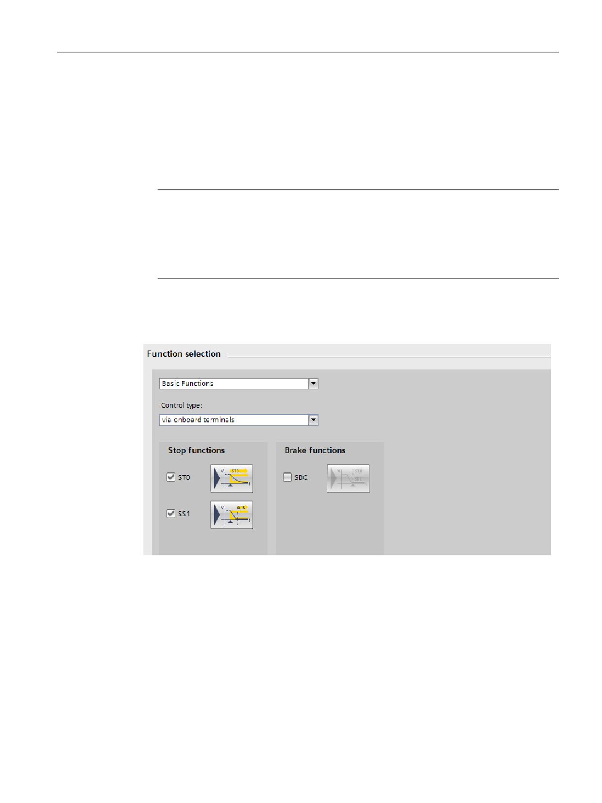
1. Select the setting "Basic Functions" in the first drop-down list:
Figure 7-2
Basic Functions
2. Select one of the following settings in the "Control type" drop-down list:
- via PROFIsafe
The "Basic functions via onboard terminals" option is automatically active.
- via onboard terminals
In the lower part of the screen form the corresponding functions are active.
3. Click the button for the required function.
The corresponding screen form is displayed.
4. Parameterize the function (see Chapter "Basic Functions (Page 293)").
Safety Integrated
Function Manual, 06/2020, 6SL3097-5AR00-0BP3
289
Commissioning
7.8 Commissioning: Basic procedure
Making the basic settings for the Safety Integrated Extended/Advanced Functions
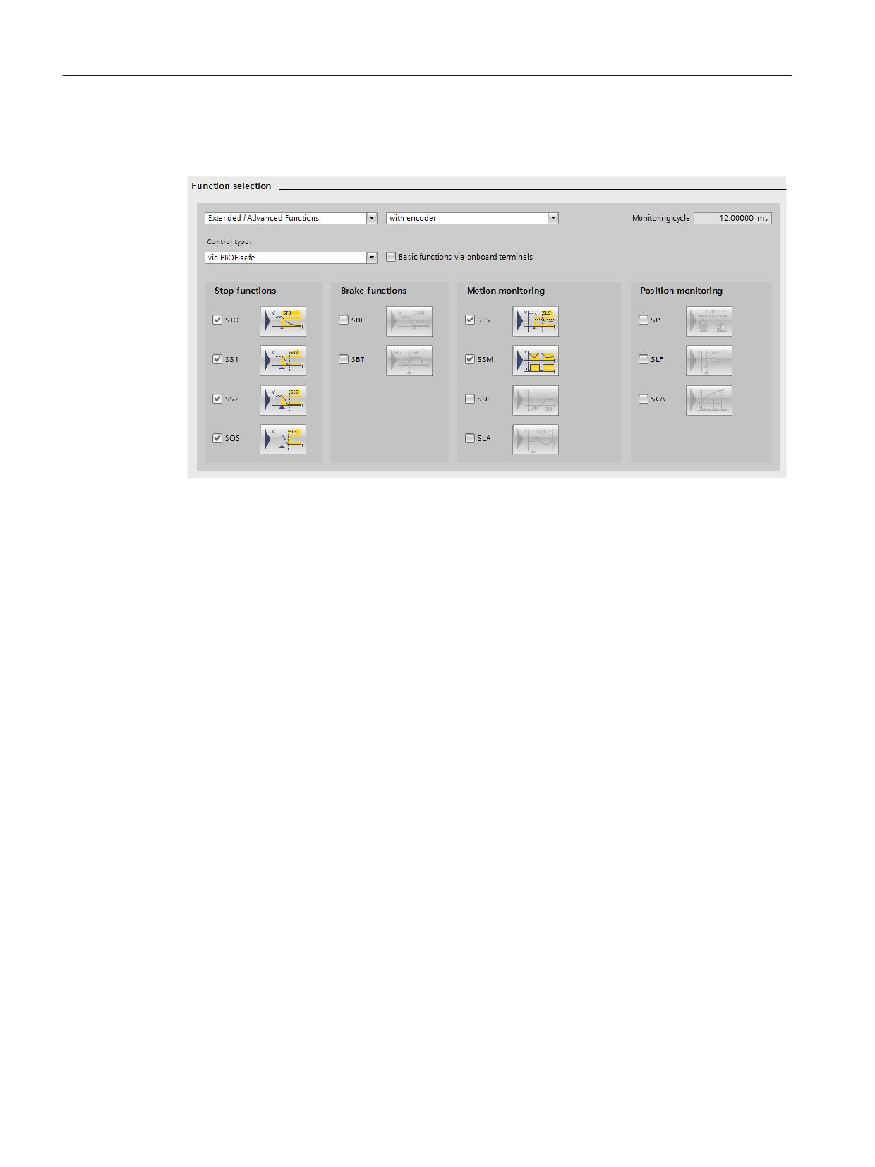
1. Select the setting "Extended/Advanced Functions" in the first drop-down list.
Figure 7-3
Extended Functions
2. In the second drop-down list, select whether a safety-capable encoder is used:
- with encoder
- without encoder
3. Select one of the following settings in the "Control type" drop-down list:
- via PROFIsafe
The "Basic functions via onboard terminals" option is automatically active.
- without selection
Only for SBC, SBT, SDI and SLS. SBT only for Extended / Advanced Functions with an
encoder.
4. Activate or deactivate the "Basic functions via onboard terminals" option.
The associated Safety Integrated Functions are then active in the lower part of the screen
form:
- Stop functions
- Braking functions
- Motion monitoring
- Position monitoring (= Advanced Functions)
5. Click the button for the required Safety Integrated Function.
Parameterize the function (see Chapter "Extended and Advanced Functions (Page 297)").
Safety Integrated
290
Function Manual, 06/2020, 6SL3097-5AR00-0BP3

Commissioning
7.8 Commissioning: Basic procedure
7.8.1.3
Accepting the settings in the drive
After you have parameterized all safety functions, the drive must accept the settings.
Note
To accept the settings in the drive, it must be online.
1. To accept the settings and deactivate the safety functions, click the
icon in the toolbar.
The following steps are executed:
- The parameter settings are copied from CPU 1 to CPU 2.
- Copy RAM to ROM is offered.
- Safety mode is deactivated, the icon now has a yellow border.
2. Go offline with the drive.
You can now continue with the further settings of the parameterization. The dialogs are no
longer deactivated.
7.8.1.4
Changing the safety password
❒ "Drive axis > Parameter > Safety Integrated > Enter password"
The safety password protects safety parameters against maloperation. Always assign a strong
password, to enable protection. To reset the password to the factory setting, you require the
valid password.
Note
The safety password does not have the equivalent quality of a password (protection against
unauthorized access, e.g. by an attacker), but rather that of write protection (e.g. protection
against maloperation).
Requirement
● The drive axis is ONLINE.
The safety password can only be read or changed in online mode.
Safety Integrated
Function Manual, 06/2020, 6SL3097-5AR00-0BP3
291
Commissioning
7.8 Commissioning: Basic procedure
Procedure
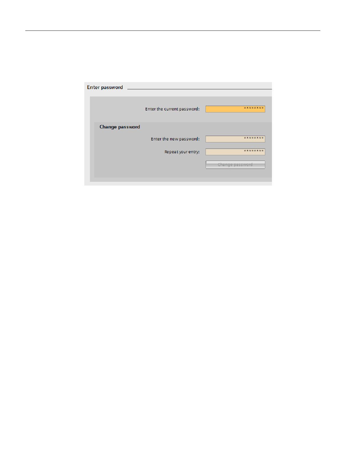
To change the safety password, proceed as follows:
1. Enter the current password at the top.
Figure 7-4
Entering the password
2. Enter the new password at the bottom.
3. Enter the new password again at the bottom.
4. Click "Change password" to accept the new password.
Safety Integrated
292
Function Manual, 06/2020, 6SL3097-5AR00-0BP3
Commissioning
7.8 Commissioning: Basic procedure
7.8.2
Basic Functions
7.8.2.1
Commissioning with Startdrive
Configuring Safety Functions
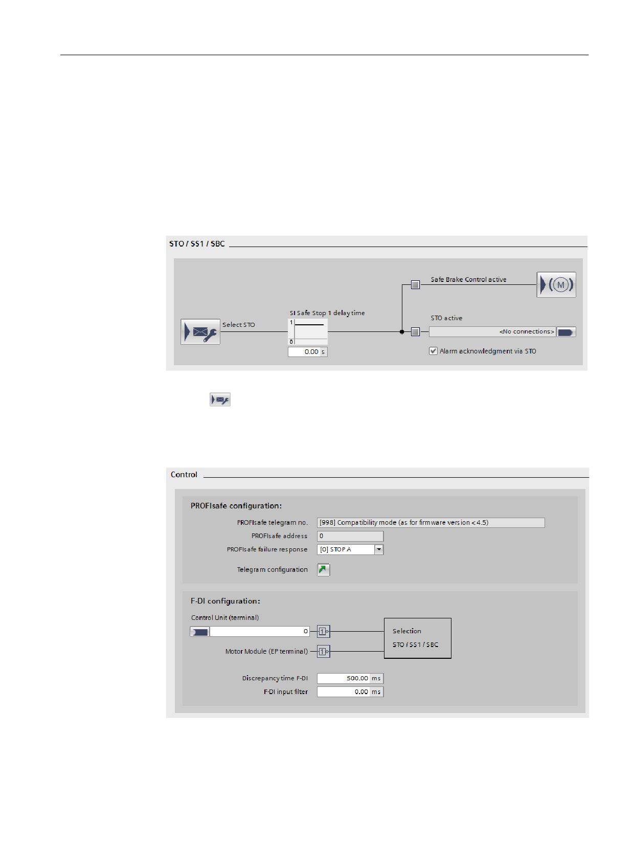
Proceed as follows to configure the Safety Integrated Functions STO, SS1 and SBC:
1. Call the "STO/SS1/SBC" safety functions.
Figure 7-5
Safety Integrated Basic Functions STO, SS1 and SBC
2. Click the
button ("Select STO") to configure the STO function.
The "Control" screen form opens. The display of the screen form depends on the basic
settings of the Safety Integrated Basic Functions.
3. In this screen form, configure the controls via the fail-safe inputs and outputs and/or
PROFIsafe.
Figure 7-6
Example: Control of STO
4. Call "STO/SS1/SBC" again.
Safety Integrated
Function Manual, 06/2020, 6SL3097-5AR00-0BP3
293
Commissioning
7.8 Commissioning: Basic procedure
5. To configure the "SS1" function, set the delay time until the start of "STO" in the "Safe stop
1 delay time" field.
6. Then connect the signal source r9773.1 for the "STO active in the drive" function.
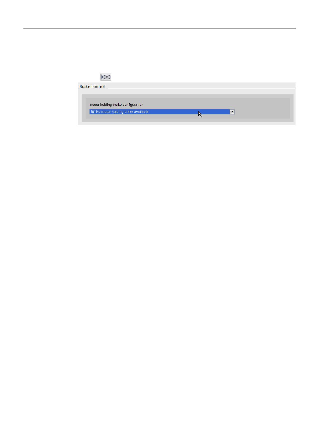
7. Click the
button (brake control) to configure the "SBC" function.
Figure 7-7
Example: Brake control without motor holding brake
8. Click "Save project" in the toolbar to save the changes in the project.
9. Accept these settings in the drive: Chapter "Accepting the settings in the drive (Page 291)"
Result
You have configured the Safety Integrated Basic Functions.
Safety Integrated
294
Function Manual, 06/2020, 6SL3097-5AR00-0BP3

Commissioning
7.8 Commissioning: Basic procedure
7.8.2.2
Commissioning via direct parameter access
To commission the Basic Functions "STO", "SBC" and "SS1" via terminals, proceed as follows:
Table 7-2
Commissioning the "STO", "SBC" and "SS1" Basic Functions
No.
Parameter
Description/comments
1
p0010 = 95
Setting Safety Integrated commissioning mode.
● The following alarms and faults are output:
- A01698 (SI CU: Commissioning mode active)
During first commissioning only:
- F01650 (SI CU: Acceptance test required) with fault value = 130 (no Safety Integrated
parameters exist for the Motor Module).
- F30650 (SI MM: Acceptance test required) with fault value = 130 (no Safety Integrated
parameters exist for the Motor Module).
Acceptance test and test certificate, see step 17.
● The pulses are safely suppressed.
● An existing and parameterized motor holding brake has already been applied.
● In this mode, fault F01650 or F30650 with fault value = 2003 is output after a Safety Inte-
grated parameter is changed for the first time.
This behavior applies for the entire duration of Safety Integrated commissioning, that means, the
"STO" function cannot be selected/deselected while Safety Integrated commissioning mode is
active because this would constantly force safe pulse suppression.
2
p9761 = "Value"
Entering Safety Integrated password.
When Safety Integrated is commissioned for the first time, the following applies:
● Safety Integrated password = 0
● Default setting for p9761 = 0
This means that the Safety Integrated password does not need to be set during first commis-
sioning.
3
p9601.0 = 1
Enabling "Safe Torque Off" function (STO).
4
p9602 = 1
Enabling "Safe Brake Control" function (SBC).
● SBC cannot be used alone, but only in conjunction with one of the STO and SS1 functions.
5
p9652 > 0
Enabling "Safe Stop 1" function (SS1).
● The "Safe Stop 1" function is not activated until at least one Safety Integrated monitoring
function has been enabled (i.e. p9601 ≠ 0).
Safety Integrated
Function Manual, 06/2020, 6SL3097-5AR00-0BP3
295

Commissioning
7.8 Commissioning: Basic procedure
No.
Parameter
Description/comments
6
p9620 = "fast DI on
Set terminals for "Safe Torque Off (STO)".
CU"
Wire terminal "EP" (enable pulses) on the Motor Module.
Terminal "EP"
● Control Unit monitoring channel:
By appropriately interconnecting BI: p9620 for the individual drives, the following is possible:
- Selecting/deselecting the STO
- Grouping the terminals for STO
● Motor Module monitoring channel:
By wiring the "EP" terminal accordingly on the individual Motor Modules, the following is
possible:
- Selecting/deselecting the STO
- Grouping the terminals for STO
Note:
The STO terminals must be grouped identically in both monitoring channels.
7
Set F-DI changeover tolerance time.
p9650 = "Value"
F-DI changeover tolerance time on Control Unit
● The parameter is not changed until Safety Integrated commissioning mode has been exited
(i.e. when p0010 ≠ 95 is set).
● Due to the different runtimes in the two monitoring channels, an F-DI changeover (e.g.
selection/deselection of STO) does not take immediate effect. After an F-DI changeover,
dynamic data is not subject to a data cross-check during this tolerance time.
8
p9651 = "Value"
Debounce time for the failsafe digital inputs to control STO/SBC/SS1
9
p9658 = "Value"
Set transition period from STOP F to STOP A.
● STOP F is the stop response that is initiated when the data cross-check is violated as a result
of fault F01611 or F30611 (SI: Defect in a monitoring channel). STOP F initiates "No stop
response" as default setting.
● After the parameterized time has expired, STOP A (immediate Safety Integrated pulse in-
hibit) is triggered by the fault F01600 or F30600 (SI: STOP A triggered).
The default setting for p9658 is 0 (i.e. STOP F immediately results in STOP A).
10
p9659 = "Value"
Time for carrying out forced checking procedure and testing the Safety Integrated shutdown
paths.
● After this time has expired, the user is requested to test the switch-off paths as a result of
alarm A01699 (SI CU: Necessary to test the switch-off signal paths) (i.e. select/deselect
STO).
● The commissioning engineer can change the time required for carrying out the forced
checking procedure and testing the Safety Integrated shutdown paths.
11
Setting a new Safety Integrated password.
p9762 = "Value"
Enter a new password.
p9763 = "Value"
Confirm the new password.
● The new password is not valid until it has been entered in p9762 and confirmed in p9763.
● As of now, you must enter the new password in p9761 to change Safety Integrated param-
eters.
● Changing the Safety Integrated password does not mean that you have to change the
checksums.
Safety Integrated
296
Function Manual, 06/2020, 6SL3097-5AR00-0BP3

Commissioning
7.8 Commissioning: Basic procedure
No.
Parameter
Description/comments
12
Parameterizing Safe Brake Adapter.
p9621 = "value"
● Set with p9621 the signal source for the Safe Brake Adapter.
p9622[0...1] = "val-
● Set with p9622 the wait times for switching on and switching off the Safe Brake Adapter relay.
ue"
13
Saving and copying the Safety Integrated Functions parameters.
p9700 = 57 hex
After setting the specific parameters of the Safety Integrated Functions, they must be copied
from the Control Unit into the Motor/Power Module and then activated:
p9701 = DC hex
● p9700 SI Motion copy function
● p9701 SI Motion confirm data change
14
p0010 = 0
Exiting Safety Integrated commissioning mode.
● The checksums are checked if at least one Safety Integrated monitoring function is enabled
(p9601 ≠ 0):
If the target checksum on the Control Unit has not been correctly adapted, then fault F01650
(SI CU: Acceptance test required) is output with fault code 2000 and it is not possible to exit
the Safety Integrated commissioning mode.
If the target checksum on Motor Modules has not been correctly adapted, then fault F01650
(SI CU: Acceptance test required) is output with fault code 2001 and it is not possible to exit
the Safety Integrated commissioning mode.
● If a Safety Integrated monitoring function has not been enabled (p9601 = 0), the Safety
Integrated commissioning mode is exited without the checksums being checked.
When the Safety Integrated commissioning mode is exited, the following is carried out:
● A POWER ON must be performed after the initial commissioning. This is indicated with the
A01693 message.
15
p0971 = 1
All drive parameters (entire drive group or only single axis) must be manually saved from RAM
to ROM. This data is not saved automatically!
p0977 = 1
16
POWER ON
Carry out POWER ON.
After commissioning, a reset must be carried out with POWER ON.
17
-
Carry out acceptance test and create test certificate.
Once Safety Integrated commissioning is complete, the commissioning engineer must carry out
an acceptance test for the enabled Safety Integrated monitoring functions.
The results of the acceptance test must be documented in an acceptance certificate.
7.8.3
Extended and Advanced Functions
The following is a description of how you commission the Safety Integrated Extended Functions
in Startdrive, using SS1 as an example. The screen forms shown here are examples from the
offline commissioning. To complete commissioning, you must subsequently establish an online
connection between Startdrive and the drive.
Safety Integrated
Function Manual, 06/2020, 6SL3097-5AR00-0BP3
297
Commissioning
7.8 Commissioning: Basic procedure
7.8.3.1
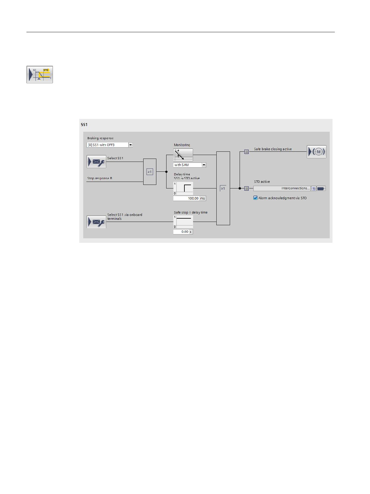
SS1 (Extended Functions)
Make the settings for the motor deceleration in the "SS1" screen form. The "SS1" function
brakes the motor, monitors the magnitude of the motor deceleration within specified limits, and
after a delay time or violation of a speed threshold, triggers the "STO" function.
Safe Stop 1 (example)
Figure 7-8
Safe Stop 1 (example)
Configuring the motor deceleration with internal braking response (OFF 3)
1. Select the "[0] SS1 with OFF 3" setting from the "Braking response" drop-down list.
The screen form is structured accordingly.
2. Select the monitoring type in the "Monitoring" drop-down list:
- with SAM
- with SBR
3. Click "Monitoring" and parameterize the alternative brake monitoring functions "SAM" and
"SBR" in the dialog.
4. Enter the required delay time in the "Delay time SS1 -> STO active" (p9556) input field.
5. Enter the required delay time in the "Safe stop 1 delay time" (p9652) input field.
6. Interconnect the signal source "STO active in the drive" (r9773.1).
7. If you want to receive an alarm acknowledgment via STO, activate the option with the same
name.
8. Click "Save project" in the toolbar to save the changes in the project.
Safety Integrated
298
Function Manual, 06/2020, 6SL3097-5AR00-0BP3
Commissioning
7.8 Commissioning: Basic procedure
Configuring the motor deceleration with external stop
WARNING
Any axis motion is possible
During the delay time (p9652), for "Safe Stop 1 (time-controlled) with external stop", any axis
movements are possible.
1. Select the "[1] SS1E external stop" setting from the "Braking response" drop-down list.
The screen form is structured accordingly.
2. Enter the required delay time in the "Delay time SS1 -> STO active" (p9556) input field.
3. Enter the required delay time in the "Safe stop 1 delay time" (p9652) input field.
4. Interconnect the signal sink "STO active in the drive" (r9773.1).
5. If you want to receive an alarm acknowledgment via STO, activate the option with the same
name.
6. Click "Save project" in the toolbar to save the changes in the project.
Completing parameter assignment
● Parameterize all the functions you have selected in a similar way.
● Accept these settings in the drive: Chapter "Accepting the settings in the drive (Page 291)"
7.8.4
General settings
7.8.4.1
Parameterizing the actual value acquisition / mechanical system
The actual value acquisition / mechanical system can only be parameterized for the Extended
Functions.
For parameterization of the actual value acquisition, only the parameters required for your
configuration are offered:
Param-
Required for the configuration:
eter
- Encoder system
- Motor type
- Axis type
①
②
③
④
⑤
⑥
⑦
Axis type
p9502
x
x
x
x
x
x
x
Select the "Linear axis" or "Rotary axis / spindle" axis type.
Topology
p9526
x
x
x
x
x
-
-
Select whether you are using a "1-encoder system" or a "2-
encoder system."
Safety Integrated
Function Manual, 06/2020, 6SL3097-5AR00-0BP3
299

Commissioning
7.8 Commissioning: Basic procedure
Param-
Required for the configuration:
eter
- Encoder system
- Motor type
- Axis type
①
②
③
④
⑤
⑥
⑦
Modulo range - only for rotary axis / spindle
p9505
x
x
x
-
-
-
-
Set the modulo value in degrees for rotary axes for the "Safe
Position" function here. This modulo value is taken into ac-
count for safe homing and for the transfer of the safe position
via PROFIsafe when absolute position is enabled.
The safety functions are executed in the sampling time dis-
p9500
x
x
x
x
x
x
x
played in the "Monitoring cycle".
The actual value acquisition cycle defines the cycle time in
p9511
x
x
x
x
x
x
x
which the actual values for Safety Integrated are acquired.
● A slower cycle time reduces the maximum permissible ve-
locity, but also reduces the load on the Control Unit for safe
actual value acquisition.
● The maximum permissible velocity which, if overshot, can
trigger faults in the safe actual value acquisition, is dis-
played in r9730.
Setting criteria if the motion monitoring functions are executed
without an encoder:
● The actual value acquisition cycle must be set the same as
the current controller cycle (p0115).
The "Accept encoder data" button is available online and al-
-
x
x
x
x
x
x
x
lows you to update the safety parameters.
Depending on whether the configuration is a 1-encoder or 2-
encoder system, the appropriate encoder parameters are cop-
ied from the basic system to the corresponding safety param-
eters.
Direction of rotation reversal
p9539[
x
x
x
-
-
-
-
0]
Here, you can set whether a direction of rotation reversal is
involved for the particular gearbox.
Pulse number
p9518
x
x
x
x
x
-
-
This field shows the number of pulses of the encoder used.
Fine resolution
p9519
x
x
x
x
x
-
-
This field shows the number of bits of the encoder control word
used.
Load revolutions / encoder revolutions
p9521
x
x
x
-
-
x
x
In this section you can parameterize a gear ratio for the en-
p9522
coders used. The gear ratio is the ratio of encoder revolutions
to revolutions of the drive shaft (load revolutions).
● "Number of load revolutions" allows you to enter the num-
ber of load revolutions.
● "Number of encoder revolutions" allows you to enter the
number of encoder revolutions.
Safety Integrated
300
Function Manual, 06/2020, 6SL3097-5AR00-0BP3

Commissioning
7.8 Commissioning: Basic procedure
Param-
Required for the configuration:
eter
- Encoder system
- Motor type
- Axis type
①
②
③
④
⑤
⑥
⑦
Gear ratio
p9321
x
-
-
-
-
-
-
Sets the denominator and numerator for the gearbox between
p9322
the encoder (or motor for encoderless monitoring functions)
and load.
Here, you parameterize the number of encoder pulses for the
p9318
x
-
x
-
x
-
-
encoder that is used for safe motion monitoring on the Motor
Module.
Here, you parameterize the fine resolution for the encoder that
p9319
x
-
x
-
x
-
-
is used for safe motion monitoring on the Motor Module.
The mean value of the actual values of both channels is cal-
p9501.
x
-
x
-
x
-
-
culated cyclically after actual value synchronization has been
3
activated, for example, for systems or machines with slip. The
maximum slip defined in p9549 is monitored once per cross-
check cycle (r9724).
If "Actual value synchronization" is not enabled, the value par-
ameterized in p9542 is used as tolerance value for the cross-
checking.
Actual value tolerance
p9542
x
-
x
-
x
x
x
Here, you set the tolerance for the crosswise comparison of
the actual position between the two monitoring channels
Velocity tolerance
p9549
x
-
x
-
x
-
-
Here, you set the maximum tolerance for the crosswise com-
parison of the actual velocity (only if actual value synchroniza-
tion has been activated).
Leadscrew pitch
p9520
-
-
-
-
-
x
-
Here, you set the transmission ratio between the encoder and
load in mm (linear axis with rotary encoder) (only available for
linear axis).
Pole pair number
p0313
-
-
-
-
-
x
x
The safe actual value acquisition without encoder calculates
the electric speed of the drive. The pole pair number specifies
the factor with which the electrical speed must be multiplied in
order to obtain the mechanical speed at the motor shaft.
Legend for table header:
①
2-encoder, rotary, rotary
②
1-encoder, rotary, linear
③
2-encoder, rotary, linear
④
1-encoder, linear, linear
⑤
2-encoder, linear, linear
⑥
Without encoder, linear
⑦
Without encoder, rotary
Safety Integrated
Function Manual, 06/2020, 6SL3097-5AR00-0BP3
301
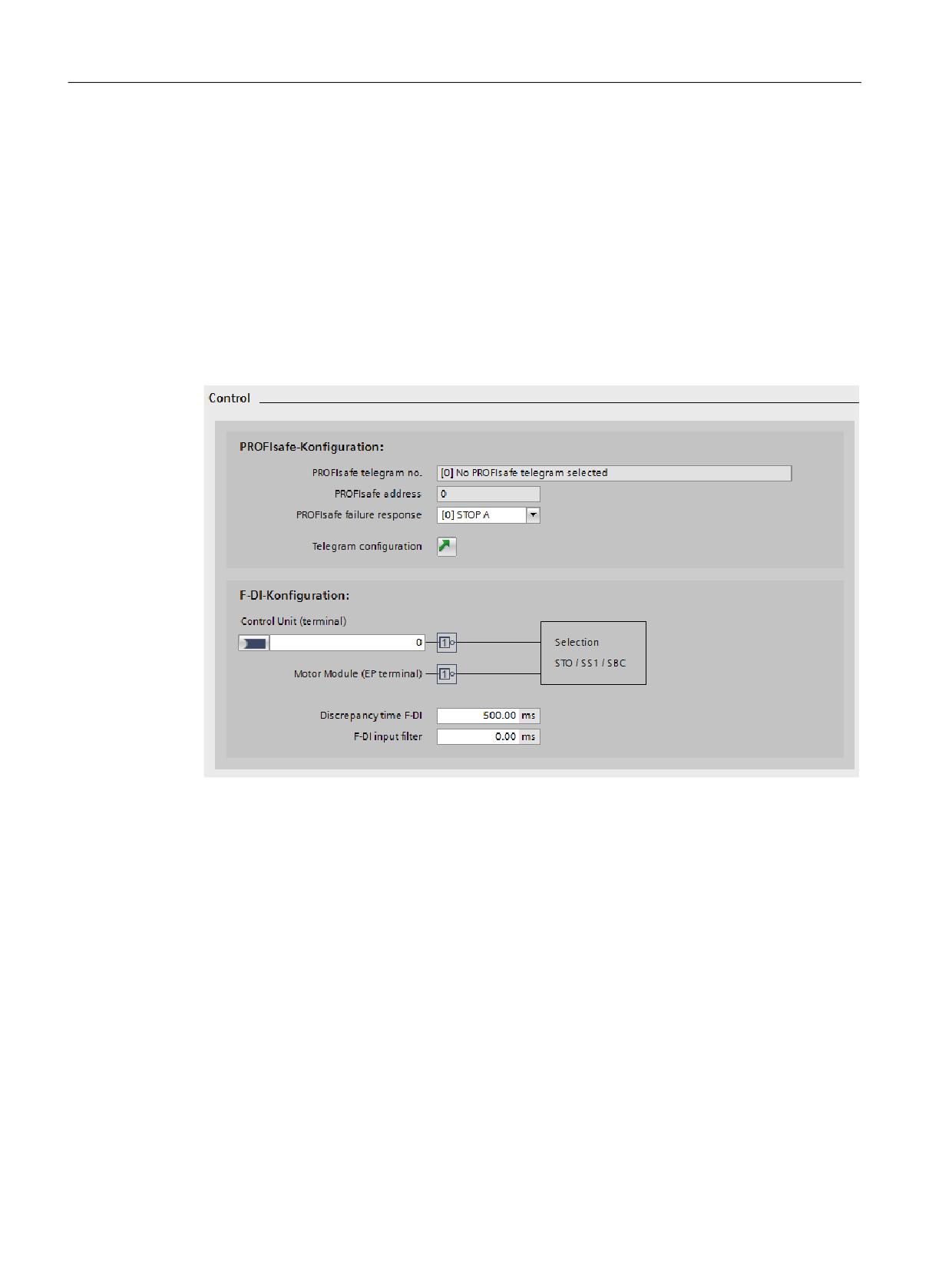
Commissioning
7.8 Commissioning: Basic procedure
7.8.4.2
Configuring the control of the safety functions
❒ "Drive axis > Parameter > Safety Integrated > Control"
Control
In the "Control" screen form, you can parameterize the settings of the SINAMICS S120 for the
failsafe inputs and outputs or the control via PROFIsafe.
In this screen form, Startdrive shows only those parameters that you have to take into account
for the selected control mode.
Figure 7-9
Example: Control via PROFIsafe and F-DI
F-DI configuration
The signal states on the two terminals of an F-DI are then monitored whether they attain the
same logical signal state within the discrepancy time.
The time delay that is unavoidable due to mechanical switching, for example, can be adapted
via parameters. The time within which the selection or deselection must be performed in both
monitoring channels in order to qualify as "simultaneous", is specified with p9650.
Safety Integrated
302
Function Manual, 06/2020, 6SL3097-5AR00-0BP3
Commissioning
7.8 Commissioning: Basic procedure
For internal faults or limit value violations, the drive-internal safety functions issues safety faults.
1. Interconnect signal source p9620 for STO, SS1 or SBC to the Control Unit.
Only the fixed zero and digital inputs DI 0 ... 7, 16, 17, 20 and 21 are permissible as signal
sources.
2. Enter a discrepancy time in the "Discrepancy time" (p9650) field.
3. Enter a time for the input filter (debounce time) in the "F-DI input filter" (p9651) field.
The debounce time is rounded off to whole ms and then accepted. This debounce time
applies for the F-DIs and the readback input for the forced checking procedure. The
debounce time specifies the maximum time an interference pulse can be present at F-DIs
before being interpreted as a switching operation.
PROFIsafe configuration
The PROFIsafe address is required for control of the safety functions via PROFIsafe.
1. Click the icon "Telegram configuration"
The properties of the PROFINET interface are displayed in the Inspector window. The
"Cyclic data traffic" setting range is active. Here you define the telegrams for the drive
objects.
2. Click the <Add telegram> entry in the telegram configuration of "Drive axis_x".
3. Select the "Add safety telegram" option in the drop-down list of the entry:
Startdrive then inserts the "Safe actual value" and "Safe setpoint" lines. The relevant
PROFIsafe telegrams are preassigned.
4. Open the new "Safe setpoint" screen form (for Drive axis_x) in the Inspector window.
5. Correct the PROFIsafe address of the drive in the "F-address" field.
6. In the function view, switch back to the "control" screen form.
The value of the F-address is displayed in the "PROFIsafe address" (p9610) field. A
preassigned PROFIsafe telegram is displayed in the "PROFIsafe telegram no." drop-down
list.
7. Click "Accept values" to transfer the telegram from the default settings into the Safety
programming.
8. Select the desired stop response for a failure of the PROFIsafe communication in the
"PROFIsafe failure response" (p9612) drop-down list.
Safety Integrated
Function Manual, 06/2020, 6SL3097-5AR00-0BP3
303
Commissioning
7.8 Commissioning: Basic procedure
Note
Unique PROFIsafe addresses
You must ensure the unique assignment of the PROFIsafe address throughout the network and
the CPU.
● The fail-safe I/O of PROFIsafe address type 1 is addressed clearly by its fail-safe
destination address.
● The fail-safe destination address of the fail-safe I/O (drive units in this case) must be unique
for the entire fail-safe I/O throughout the network and the CPU (system-wide). The fail-safe
I/O of PROFIsafe address type 2, e.g. modules of the ET 200SP type, must also be taken
into account.
● Note also the corresponding documentation in the TIA Portal online help in Section
"SIMATIC Safety - Configuration and programming". (SDR001)
Without selection - configuration
As an alternative to controlling via terminals and/or PROFIsafe, there is also the option to
parameterize the "SDI" or the "SLS" functions without selection. In this case, the SDI function
is permanently active after POWER ON (with encoder) or becomes active after switching on
(without encoder) (see SDI (Extended Functions) (Page 65)). With the "SLS" function without
selection, there is no delay time and the function is permanently active after POWER ON (with
encoder), or it becomes active when switched on (without encoder) (see SLS (Extended
Functions) (Page 56)).
1. Select whether SLS or SDI should be selected permanently in the respective drop-down list.
7.8.4.3
Forced checking procedure (test stop)
❒ "Drive axis > Parameter > Safety Integrated > Test stop"
"Test stop” screen form
Parameterize the settings for the forced checking procedure (test stop) in the "Test stop"
screen form.
To meet the requirements of the DIN EN ISO 13849-1 and IEC 61508 standards in terms of
timely fault detection, the converter must test its safety-related circuits regularly - at least once
a year - for correct functioning. The converter monitors the regular test of its safety-related
circuits that monitor the speed of the motor, and to safely interrupt the torque-generating energy
supply to the motor through the safe pulse suppression.
Safety Integrated
304
Function Manual, 06/2020, 6SL3097-5AR00-0BP3
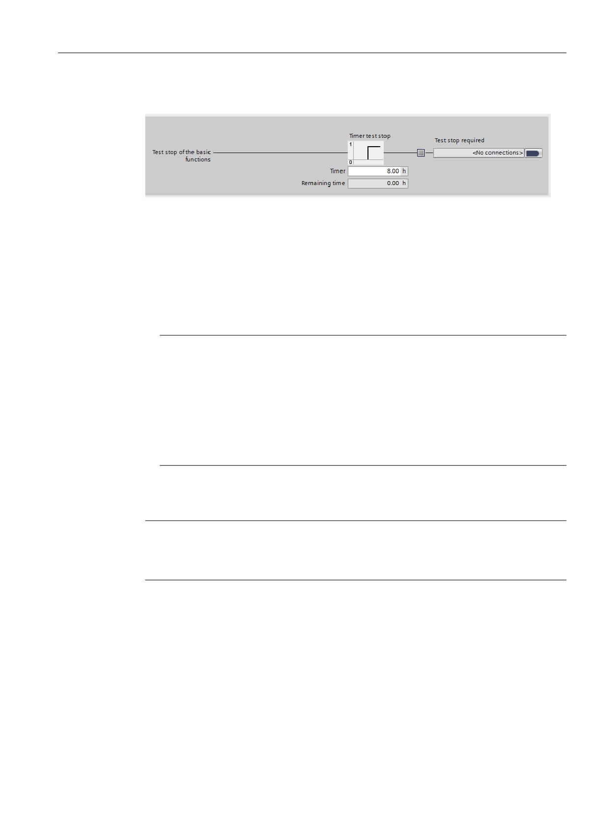
Commissioning
7.8 Commissioning: Basic procedure
Test stop for Basic Functions
Figure 7-10
Example: Basic Functions
To parameterize the forced checking procedure (test stop) for the Basic Functions, proceed as
follows:
1. Enter the interval for performing dynamization and testing the safety shutdown paths in the
"Timer" (p9659) field.
Within the parameterized time, the "STO" function must be selected and deselected at least
once. The monitoring time is reset at every STO deselection.
2. Connect the "Test stop required" (r9773.31) signal sink to a digital output or to a bit in the
status word of the fieldbus.
Note
Resetting the timer of the Basic Functions
If the associated forced checking procedure (test stop) is performed, while simultaneously
using the Extended/Advanced Functions, the Basic Functions timer is also reset.
While STO is selected via the Extended/Advanced Functions, the terminals for the selection
of the Basic Functions are not checked for discrepancy. This means that the forced
checking procedure (test stop) of the Basic Functions must always be performed without the
selection of STO or SS1 via the Extended/Advanced Functions. It is otherwise not possible
to verify the correct control by the terminals.
Extended/Advanced Functions test stop
Note
If the "Basic functions via onboard terminals" option is active for the Extended/Advanced
Functions, you must make the test stop settings for the Basic Functions as well as for the
Extended/Advanced Functions.
Safety Integrated
Function Manual, 06/2020, 6SL3097-5AR00-0BP3
305
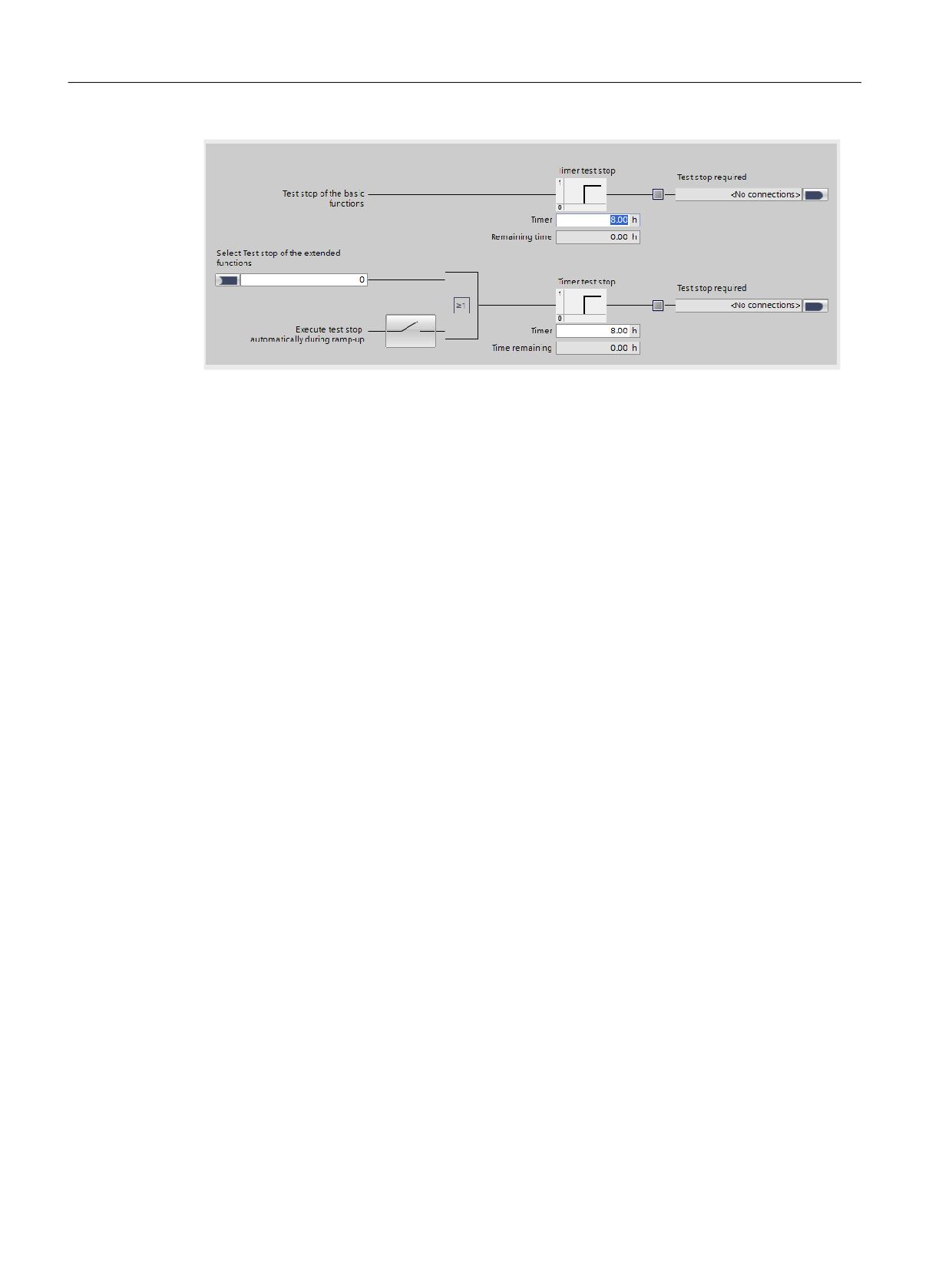
Commissioning
7.8 Commissioning: Basic procedure
Figure 7-11
Example: Extended and Advanced Functions
To parameterize the forced checking procedure (test stop) for the Extended Functions,
proceed as follows:
1. If the test stop is to be executed during ramp-up, establish a connection for "Execute test
stop automatically during ramp-up". The line in the button must be continuous.
- Or -
If the test stop is not to be executed automatically during ramp-up, select the signal (p9705)
that is to trigger the forced checking procedure. Make sure that the connection for "Execute
test stop automatically during ramp-up" is interrupted.
2. Enter the interval for performing the forced checking procedure and testing the safety
shutdown paths in the "Timer" (p9559) field.
Within the parameterized time, the "STO" function must be selected and deselected at least
once. The monitoring time is reset at every STO deselection.
3. Connect the "Test stop required" (r9723.0) signal sink to a digital output or to a bit in the
status word of the fieldbus.
Status display
The following elements show the current status of the forced checking procedure:
● Time remaining:
Shows the time remaining until the forced checking procedure and the test of the safety
shutdown paths are performed (r9660 for the Basic Functions, r9765 for the Extended
Functions).
● Test stop required:
Shows that a forced checking procedure (test stop) must be performed on the drive.
Evaluate alarm A01699 in your higher-level controller, for example, by connecting r9773.31
or r9723.0 to a digital output or a bit in the fieldbus status word (r9773.31 for the Basic
Functions, r9723.0 for the Extended/Advanced Functions).
7.8.4.4
Function status of the Safety Integrated settings
❒ "Drive axis > Parameter > Safety Integrated > Function status"
Safety Integrated
306
Function Manual, 06/2020, 6SL3097-5AR00-0BP3
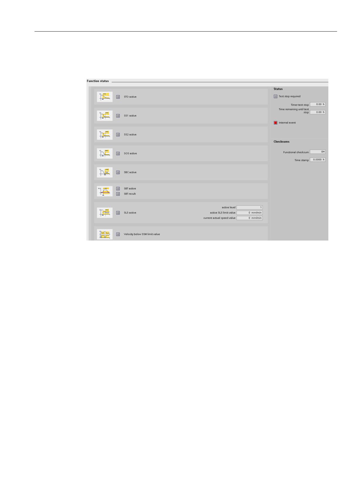
Commissioning
7.8 Commissioning: Basic procedure
"Function status" screen form
The "Function Status" screen form displays a list of all Safety Integrated Functions on the left.
Figure 7-12
Example: Safety Integrated Function status
Display
All Safety Integrated Functions activated in Startdrive are identified by a green LED.
In addition, the most important information of the selected Safety Integrated Functions is
displayed.
The status information is displayed on the right-hand side of the screen form for:
● Test stop required
Indicates that a forced checking procedure (test stop) is required.
- "Timer test stop" (p9659): Time interval for performing the forced checking procedure
and testing the safety shutdown paths. Within the parameterized time, the STO must be
selected and deselected at least once. The monitoring time is reset at every STO
deselection.
- "Remaining time" (r9660 for the Basic Functions, r9765 for the Extended Functions)
shows the time remaining until the forced checking procedure and the test of the safety
shutdown paths are performed.
● Internal event
Is set when the first safety message occurs.
● Communication failure
The communication (PROFIsafe) has failed.
Safety Integrated
Function Manual, 06/2020, 6SL3097-5AR00-0BP3
307
Commissioning
7.9 Commissioning CU310-2
7.9
Commissioning CU310-2
7.9.1
Basic sequence of commissioning
The following preconditions must be met to configure Safety Integrated on the CU310-2:
● Concluded initial commissioning of all drives
● Connect the sensors to the F-DIs and an actuator to the F-DO (if used)
Configuration sequence
1. Configuring Safety functions of the CU310-2
2. Configuring inputs (if used)
3. Configuring outputs (if used)
4. Copy parameters to the 2nd drive object
5. Change the safety password
6. Activate the configuration by selecting "Activate settings"
7. Save the entire project to Startdrive
8. Save the project in the drive by selecting "Copy RAM to ROM"
9. Execute POWER ON
10.Acceptance test
Note
Commissioning CU310-2
● The CU310-2 is still not available in Startdrive.
● You can find information on commissioning with STARTER in older editions of this manual.
7.9.2
Forced checking procedure (test stop) of the CU310-2
Testing failsafe inputs and outputs
Failsafe inputs and outputs must be tested for fail-safety at defined time intervals (forced
checking procedure or test stop). For this purpose, the CU310-2 contains a function block that
executes this forced checking procedure (test stop) for the failsafe output when selected via a
BICO source. Each time a forced forced checking procedure (test stop) is performed without
error, a timer is started to monitor the time until the next required test. After this time interval
(p10003) has elapsed and every time the Control Unit is switched on, the user is informed by
the message A01774 that a forced checking procedure (test stop) must be performed.
●
3 modes can be selected for testing the output (see following chapter).
Safety Integrated
308
Function Manual, 06/2020, 6SL3097-5AR00-0BP3

Commissioning
7.9 Commissioning CU310-2
Note
Testing the sensors for the CU310-2
Unlike TM54F, the sensors connected to the F-DI of the CU310-2 cannot be tested as part of
the forced checking procedure (test stop). The user must cyclically test sensors connected to
the F-DIs. Then it is sufficient to actuate the particular sensor and to check the corresponding
function selection.
Performing a forced checking procedure (test stop)
When parameterizing, proceed as follows:
1. Derive the suitable mode from the circuit used in your application (see figures in the
following chapters).
2. Use parameter p10047 to set the mode that is to be used.
3. Use parameter p10046 to define whether the digital output F-DO 0 is to be tested.
4. Use parameter p10001 to set the time within which the digital output signals to the
corresponding digital inputs or DIAG inputs must be recognized.
5. With parameter p10003, set the interval within which the forced checking procedure (test
stop) is to be performed. After this interval has elapsed, the user is informed by the message
A01774 that the forced checking procedure (test stop) must be performed for the F-DI/F-DO.
6. Set the signal source which triggers the start using parameter p10007. This can be, for
example, a control signal or switch via a BICO switchable signal.
While being executed, message A01772 (test stop failsafe output active) is displayed. The
messages A01772 and A01774 only disappear again after the execution. If an error has been
detected by the forced checking procedure (test stop), fault F01773 is output. Using the test
sequence specified for each mode, you can see which error has occurred from the fault value
of the test step.
WARNING
Danger to life due to unwanted movement given improper use of the feedback DI of the F-DO
With the test sequence, unwanted movements of the drive can be caused if the DI of the F-DO
is not only used for feedback with test stop/forced checking procedure but also for other
purposes.
● Only use the DI of the F-DO for the feedback signal with forced checking procedure (test
stop) - and not for other purposes.
Safety Integrated
Function Manual, 06/2020, 6SL3097-5AR00-0BP3
309
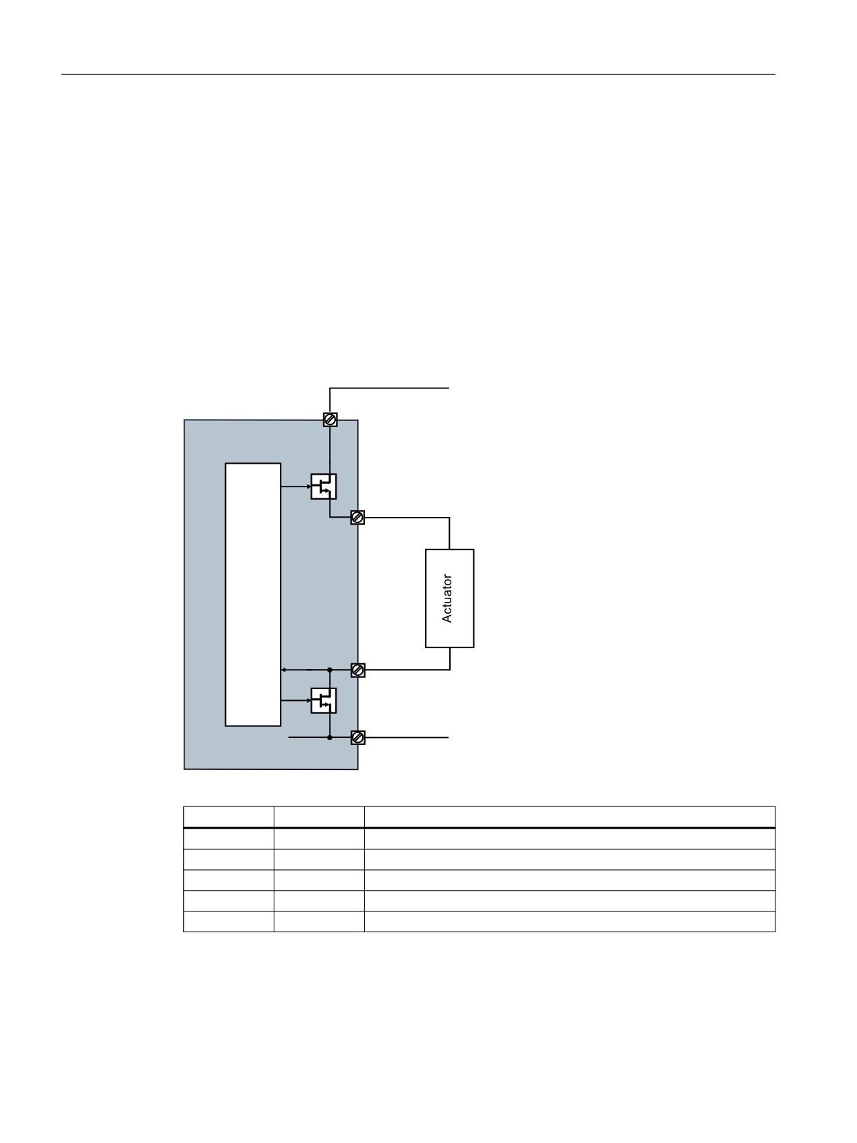
Commissioning
7.9 Commissioning CU310-2
Forced checking procedure (test stop): Duration
You can calculate the duration using this formula:
TTest stop = 8 · p9500 6 · p10001
=
+
Test of
Evaluation of the
the
active F-DIs
F-DO
7.9.2.1
Test mode 1: Evaluation of internal diagnostic signal (passive load)
([W
9
&8
'2
'2
'2
',$*
'2
0
Figure 7-13
F-DO circuit "Test mode 1: Evaluation of internal diagnostic signal (passive load)"
DO+
DO-
Expected response, DIAG signal
OFF
OFF
LOW
ON
ON
LOW
OFF
ON
LOW
ON
OFF
HIGH
OFF
OFF
LOW
Test sequence for test mode 1
Safety Integrated
310
Function Manual, 06/2020, 6SL3097-5AR00-0BP3
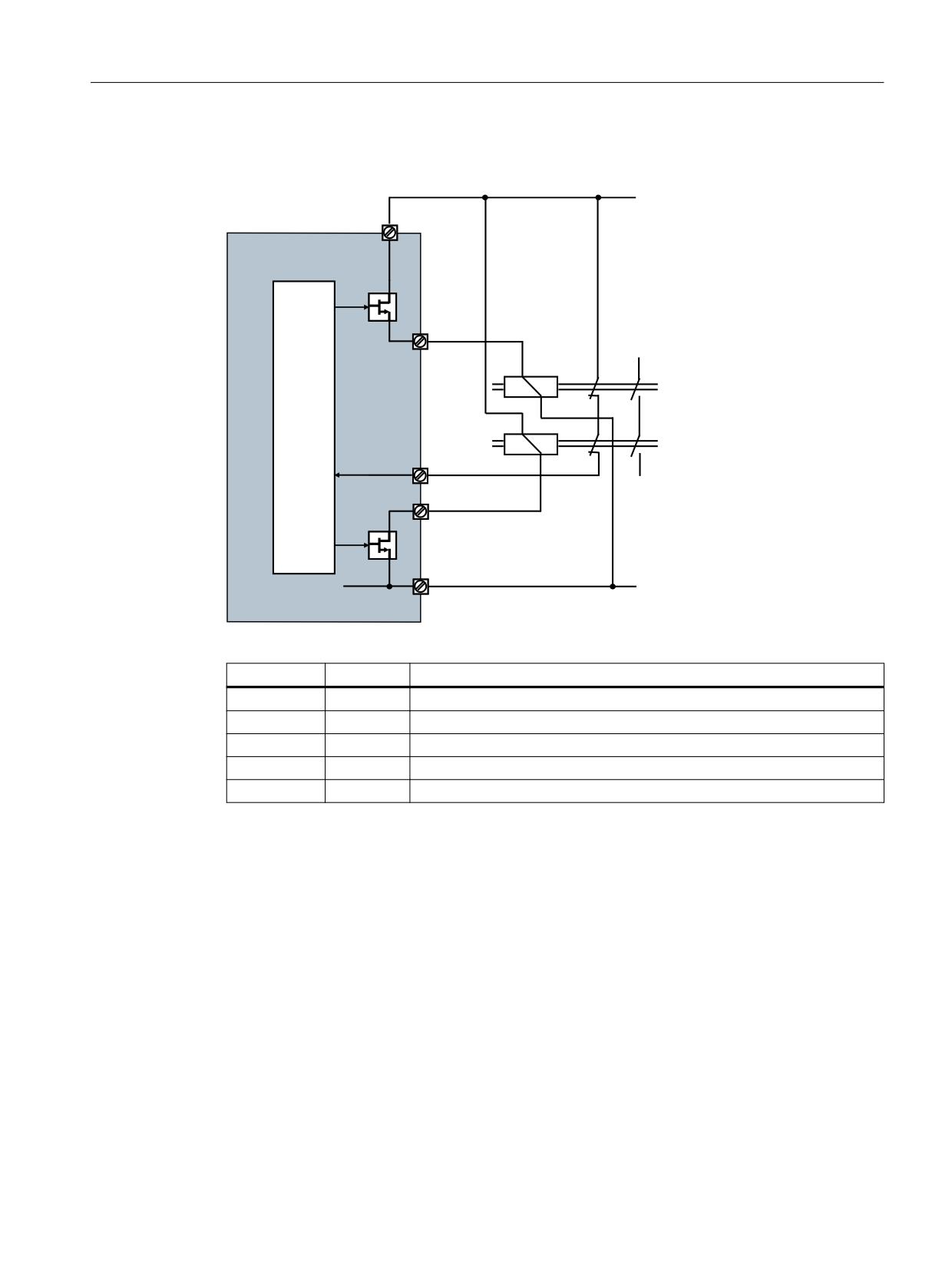
Commissioning
7.9 Commissioning CU310-2
7.9.2.2
Test mode 2: Read back F-DO in DI (relay circuit)
9
H[W
&8
'2
'2
',
',
'2
'2
0
Figure 7-14
F-DO circuit "Test mode 2: Read back F-DO in DI (relay circuit)"
DO+
DO-
Expected response, DI signal
OFF
OFF
HIGH
ON
ON
LOW
OFF
ON
LOW
ON
OFF
LOW
OFF
OFF
HIGH
Test sequence for test mode 2
Safety Integrated
Function Manual, 06/2020, 6SL3097-5AR00-0BP3
311
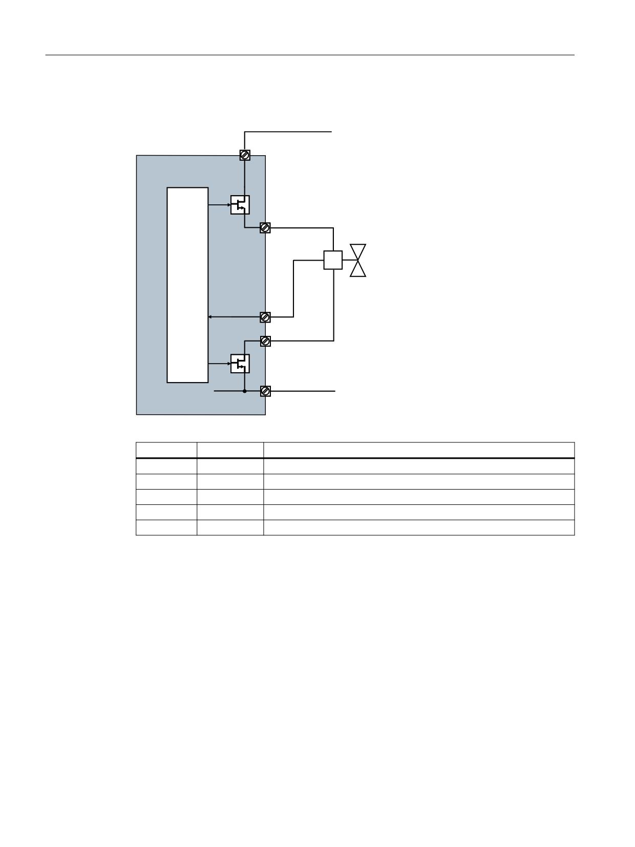
Commissioning
7.9 Commissioning CU310-2
7.9.2.3
Test mode 3: Read back F-DO into the DI (actuator with feedback signal)
9
H[W
&8
'2
'2
',
',
'2
'2
0
Figure 7-15
F-DO circuit "Test mode 3: Read back F-DO into the DI (actuator with feedback signal)"
DO+
DO-
Expected response, DI signal
OFF
OFF
HIGH
ON
ON
LOW
OFF
ON
HIGH
ON
OFF
HIGH
OFF
OFF
HIGH
Test sequence for test mode 3
Safety Integrated
312
Function Manual, 06/2020, 6SL3097-5AR00-0BP3
Commissioning
7.9 Commissioning CU310-2
7.9.2.4
Test stop mode parameters
Overview of important parameters (see SINAMICS S120/S150 List Manual)
● p9500
SI Motion monitoring clock cycle (Control Unit) (Extended and Advanced
Functions)
● p10001
SI Motion wait time for test stop at DO
● p10003
SI Motion forced checking procedure timer
● p10007
BI: SI Motion forced checking procedure F-DO signal source
● p10017
SI Motion digital inputs debounce time (CPU 1)
● p10046
SI Motion F-DO feedback signal input activation
● p10047
SI Motion F-DO test stop mode (processor 1)
Safety Integrated
Function Manual, 06/2020, 6SL3097-5AR00-0BP3
313
Commissioning
7.10 Commissioning TM54F
7.10
Commissioning TM54F
7.10.1
Basic sequence of commissioning
The following conditions must be met before you can configure the TM54F:
● Initial commissioning of all drives has been completed.
● F-DIs and F-DOs of the TM54F that are to be used must be wired.
Configuration sequence
1. Insert the TM54F
2. Configure the TM54F and generate the drive groups
3. Configure Safety functions of the drive groups
4. Configure inputs, configure outputs
5. Copy parameters to the 2nd drive object (TM54F_SL)
6. Changing the safety password
7. Activate the configuration by selecting "Activate settings"
8. Save the entire project to Startdrive
9. Save the project in the drive by selecting "Copy RAM to ROM"
10.Execute POWER ON
11.Acceptance test
Note
Commissioning TM54F
● TM54F is not yet available in Startdrive.
● You can find information on commissioning with STARTER in older editions of this manual.
7.10.2
Forced checking procedure (test stop) of the TM54F
Test failsafe inputs and outputs
Failsafe inputs and outputs must be tested for fail-safety at defined time intervals (forced
checking procedure (test stop)). The TM54F contains a function block that runs this forced
checking procedure (test stop) in the following cases:
● When selected via a BICO source
● Automatically, each time the power supply voltage is switched on (POWER ON)
Safety Integrated
314
Function Manual, 06/2020, 6SL3097-5AR00-0BP3
Commissioning
7.10 Commissioning TM54F
To monitor the time until the next required test, a timer (p10003) is started after every error-free
forced checking procedure (test stop). The message A35014 "TM54F test stop necessary" is
set on expiration of the monitored time and each time the Control Unit is switched on.
The failsafe digital inputs can be selected for the forced checking procedure (test stop) 3 modes
can be selected for testing the output (see following chapter).
When the appropriate safety devices are implemented (e.g. protective doors), it can be
assumed that running machinery will not pose any risk to personnel. The user is therefore only
informed that the forced checking procedure (test stop) is due in the form of an alarm, which
requests the user to perform forced checking procedure (test stop) at the next possible
opportunity.
Examples of when the forced checking procedure (test stop) must be performed:
● When the drives are at a standstill after the system has been switched on
● Before opening the protective door
● At defined intervals (e.g. every 8 hours)
● In the automatic mode, time and event-dependent
● Automatically, each time the power supply voltage is switched on (POWER ON)
Performing a forced checking procedure (test stop)
When parameterizing, proceed as follows:
1. Derive the suitable mode from the circuit used in your application (see figures in the
following chapters).
2. Use parameter p10047 to set the mode that is to be used.
3. Use parameter p10046 to define which digital outputs (F-DO 0 to F-DO 3) are to be tested.
Note the following:
Digital outputs that are not tested are shut down during the forced checking procedure (test
stop).
4. Use parameter p10041 to define which failsafe digital inputs are to be checked during the
test.
Inputs which do not have L1+ and L2+ power supplies may not be selected for the test.
It is only possible to test the sensors connected to the F-DIs, if these are supplied from L1+
or L2+. If F-DOs of preprocessing devices are connected, forced checking procedure (test
stop) cannot be used for this input.
5. Use parameter p10001 to set the time within which the digital output signals to the
corresponding digital inputs DI 20 ... DI 23 or DIAG inputs must be recognized. Select this
time depending on the maximum response time of the external F-DO circuit.
6. With parameter p10003, set the interval within which the forced checking procedure (test
stop) is to be performed. After this interval has elapsed, the user is informed by message
A35014 that the forced checking procedure (test stop) must be performed for the TM54F.
7. Set the signal source which triggers the start using parameter p10007. This can be, for
example, a control signal or switch via a BICO switchable signal.
Alternatively, the forced checking procedure (test stop) can be performed automatically
every time the power supply is switched on (POWER ON) (p9507.6 = 1).
Safety Integrated
Function Manual, 06/2020, 6SL3097-5AR00-0BP3
315

Commissioning
7.10 Commissioning TM54F
During execution, message A35012 (TM54F: Test stop active). The values of the F-DIs are
frozen for the duration of the forced checking procedure (test stop). The messages A35014 and
A35012 only disappear again after the execution. If an error is found during the test, fault
F35013 is output. Using the test sequence specified for each mode, you can see which error
has occurred from the fault value of the test step.
CAUTION
F-DO that are fed back must only be used for the forced checking procedure (test stop)
With the sequence, unwanted responses of the drive can be caused if the F-DO is not only
used for feedback with the forced checking procedure (test stop) - but also for other purposes.
● Note that the F-DO for feedback signals for the forced checking procedure (test stop) must
not be used other purposes.
F-DOs that are not registered for evaluation by means of p10046 are set to "0" for the duration
of the test ("failsafe values").
Forced checking procedure (test stop): Duration
The maximum time period for the test is: TTest stop = TFDIs + TFDOs
● Test of the FDIs: TFDIs = 3 · r10015 + 3 · X ms
(X = 20 ms or r10015 or p10017 - the longest time of the 3 values determines the waiting
time X)
● Test of the FDOs: TFDOs = 8 · r10015 + 6 · Y ms
(Y = p10001 or r10015 or p10017 - the longest time of the 3 values determines the wait
time Y)
The safety functions of the TM54F are executed in the sampling time displayed in r10015. This
sampling time corresponds to the lowest value of the communication sampling time entered in
p10000[0..5].
7.10.2.1
Performing test stop
Performing test stop
Proceed as follows to parameterize the test stop:
1. Determine the appropriate test stop mode for the circuits used in your application (see
diagrams in the following sections).
2. Set the test stop mode which is to be used via parameter p10047.
3. Use parameter p10046 to define whether the digital output F-DO 0 is to be tested.
4. Set the debounce time for the digital inputs using parameter p10017.
5. Use parameter p10001 to set the time within which the digital output signals to the
corresponding digital inputs or DIAG inputs must be recognized.
Safety Integrated
316
Function Manual, 06/2020, 6SL3097-5AR00-0BP3
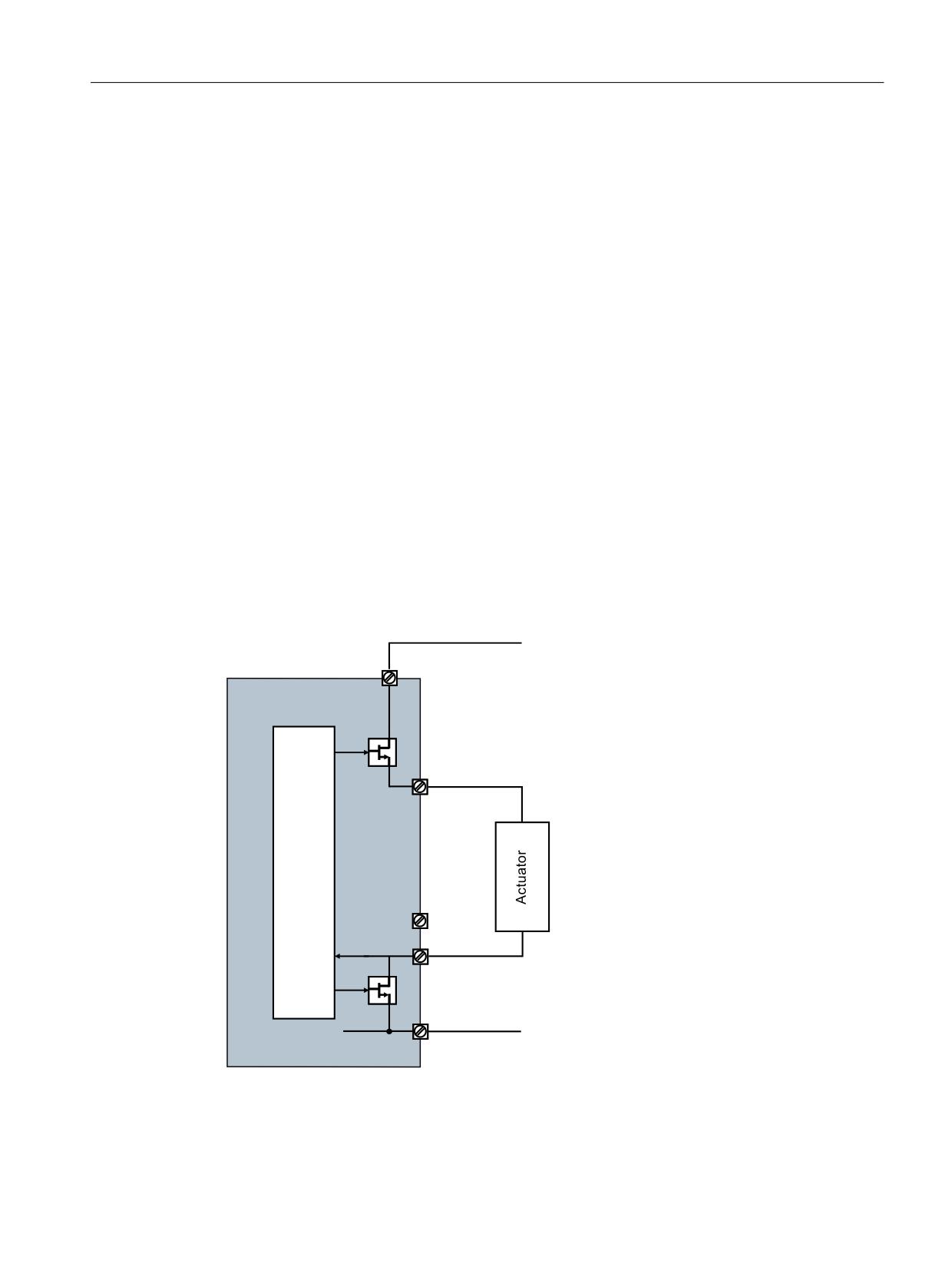
Commissioning
7.10 Commissioning TM54F
6. Use parameter p10003 to set the interval within which a test stop should be carried out. After
this time interval has expired, you will be notified via message A01774 that a test stop must
be performed for the F-DI/DO.
7. Set the signal source which triggers the start of the test stop using parameter p10007. This
can be, for example, a control signal or switch via a BICO switchable signal.
While the test stop is being carried out, the message A01772 (test stop failsafe inputs / outputs
active) appears. The messages A01772 and A01774 only disappear again after the test stop
has been performed. If an error is found during the test stop, fault F01773 is output. Using the
test sequence specified for each test stop mode, you can see which error has occurred from the
fault value of the test step.
Duration of test stop
You can calculate the duration of the test stop by using this formula:
TTest stop =
3 · p10000 +
2 · (3 ms + p10017) + 8 · p10000 +
6 · (p10001 + p10017)
Test of the Evaluation of the
Test of the Evaluation of the
F-DIs
inactive F-DIs
F-DO
active F-DIs
7.10.2.2
Test mode 1: Evaluation of internal diagnostic signal (passive load)
9
H[W
70
)
'2
'2
'2
',$*
'2
0
Figure 7-16
F-DO circuit "Test mode 1: Evaluation of internal diagnostic signal (passive load)"
Safety Integrated
Function Manual, 06/2020, 6SL3097-5AR00-0BP3
317
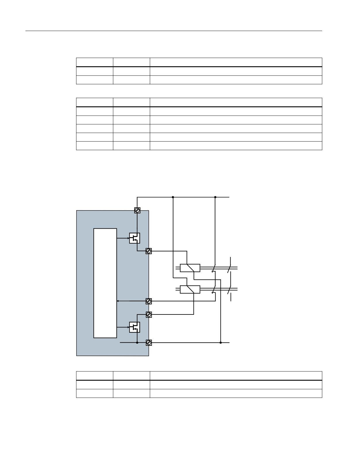
Commissioning
7.10 Commissioning TM54F
L1+
L2+
Comment
OFF
ON
F-DIs 0 ... 4 Check for 0 V
OFF
OFF
F-DIs 5 ... 9 Check for 0 V
DO+
DO-
Expected response, DIAG signal
OFF
OFF
LOW
ON
ON
LOW
OFF
ON
LOW
ON
OFF
HIGH
OFF
OFF
LOW
Test sequence for test mode 1
7.10.2.3
Test mode 2: Read back F-DO in DI (relay circuit)
9
H[W
70
)
'2
'2
',
',
'2
'2
0
Figure 7-17
F-DO circuit "Test mode 2: Read back F-DO in DI (relay circuit)"
L1+
L2+
Comment
OFF
ON
F-DIs 0 ... 4 Check for 0 V
ON
ON
F-DIs 5 ... 9 Check for 0 V
Safety Integrated
318
Function Manual, 06/2020, 6SL3097-5AR00-0BP3
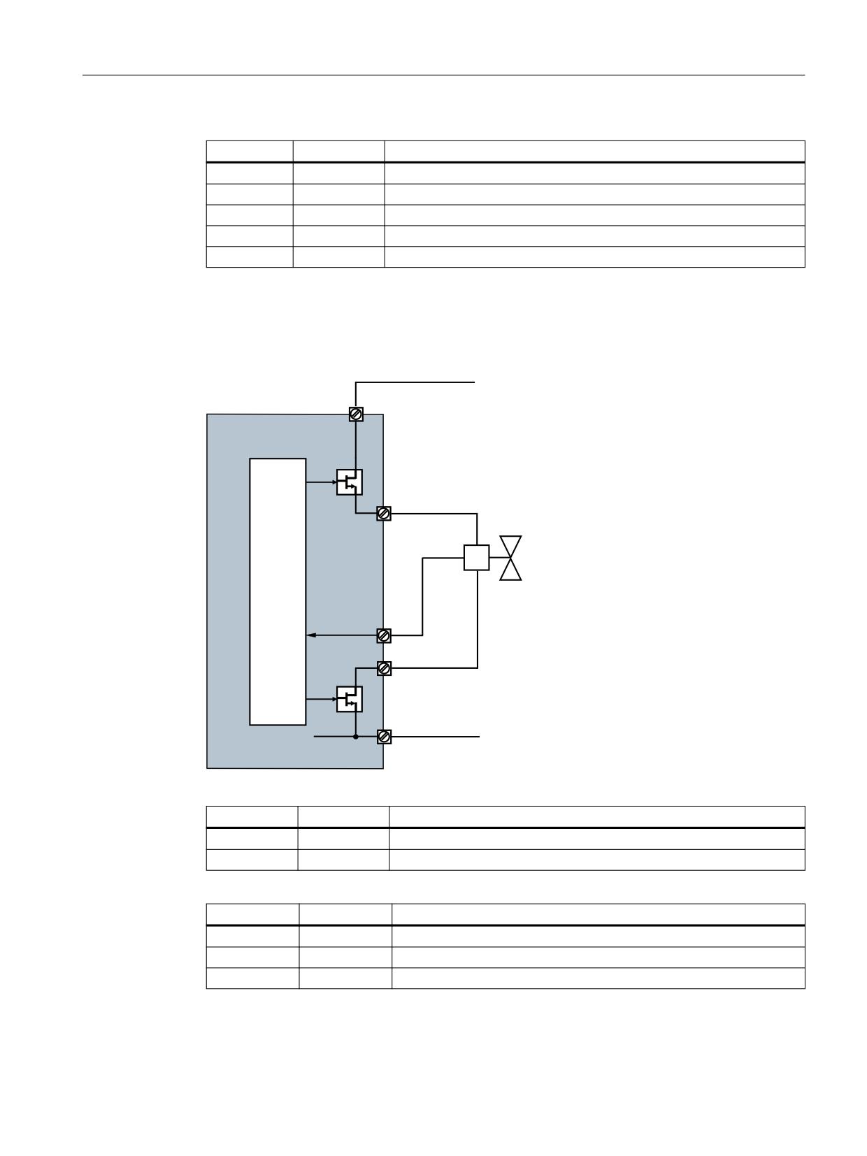
Commissioning
7.10 Commissioning TM54F
DO+
DO-
Expected response, DI signal
OFF
OFF
HIGH
ON
ON
LOW
OFF
ON
LOW
ON
OFF
LOW
OFF
OFF
HIGH
Test sequence for test mode 2
7.10.2.4
Test mode 3: Read back F-DO into the DI (actuator with feedback signal)
9
H[W
70
)
'2
'2
',
',
'2
'2
0
Figure 7-18
F-DO circuit "Test mode 3: Read back F-DO into the DI (actuator with feedback signal)"
L1+
L2+
Comment
OFF
ON
F-DIs 0 ... 4 Check for 0 V
ON
ON
F-DIs 5 ... 9 Check for 0 V
DO+
DO-
Expected response, DI signal
OFF
OFF
HIGH
ON
ON
LOW
OFF
ON
HIGH
Safety Integrated
Function Manual, 06/2020, 6SL3097-5AR00-0BP3
319

Commissioning
7.10 Commissioning TM54F
DO+
DO-
Expected response, DI signal
ON
OFF
HIGH
OFF
OFF
HIGH
Test sequence for test mode 3
7.10.2.5
Test stop mode: Function diagrams and parameters
Function diagrams (see SINAMICS S120/S150 List Manual)
●
2892
SI TM54F - configuration, F-DI/F-DO Test
Overview of important parameters (see SINAMICS S120/S150 List Manual)
● r10015
SI TM54F sampling time
● p10001
SI TM54F wait time for test stop at DO 0 ... DO 3
● p10003
SI TM54F forced checking procedure timer
● p10007
BI: SI TM54F forced checking procedure F-DI/F-DO signal source
● p10017
SI TM54F digital inputs debounce time
● p10046
SI TM54F F-DO feedback signal input activation
● p10047[0...3]
SI TM54F F-DO test stop mode
Safety Integrated
320
Function Manual, 06/2020, 6SL3097-5AR00-0BP3

Commissioning
7.11 PROFIsafe communication
7.11
PROFIsafe communication
Requirements for PROFIsafe communication
The following minimum software and hardware requirements apply for the configuration and
operation of safety-oriented communication (F communication):
Software:
● SIMATIC Manager STEP 7 V5.5 SP1 or higher
● S7 F Configuration Pack V5.5 SP51) or higher
● S7 Distributed Safety Programming V5.4 SP51) or higher
● Startdrive V15 SP1
● Drive ES Basic V5.4 SP41) or higher2)
● Correct installation of the software
Hardware:
● A control with safety functions (in our example, SIMATIC F-CPU 317F-2)
● SINAMICS S120 (in our example, a CU320-2)
● Correct installation of the devices
1)
When using a SIMATIC F-CPU
2)
As an alternative to Drive ES Basic, you can commission the communication using the GSD file.
Note
Required software or hardware components
If a single software or hardware component is either older than those specified in this document
or is missing, PROFIsafe can no longer be configured via PROFIBUS or PROFINET.
7.11.1
PROFIsafe via PROFIBUS
Note
Startdrive
Please note that you cannot yet use this function with Startdrive.
You can find information on how to commission this function with STARTER in older editions
of this manual.
Safety Integrated
Function Manual, 06/2020, 6SL3097-5AR00-0BP3
321
Commissioning
7.11 PROFIsafe communication
7.11.2
PROFIsafe via PROFINET
An example of how you can control the Safety Integrated Functions of the SINAMICS S120 with
SIMATIC S7-1500F via a PROFIsafe telegram can be found here (https://
support.industry.siemens.com/cs/ww/en/view/109749224).
7.11.3
PROFIsafe configuration with Startdrive
Activating PROFIsafe via the expert list
In order to activate the Safety Integrated Functions via PROFIsafe you must set p9601.3 = 1 in
the parameter view. Set Bit 0 to either "1" or "0", depending on whether you want to enable the
control via terminals in parallel via PROFIsafe or not. The value of p9601.2 is used to select as
to whether the Safety Integrated Basic Functions (= 0) or the Extended/Advanced Functions
(= 1) are used.
Note
In addition to configuring the PROFIsafe control, generally additional parameter changes are
required; these depend on which safety functions are used. You will find notes on this in
Chapter "Description of Safety Integrated functions (Page 75)".
Saving and copying the Safety Integrated function parameters
● After setting the specific parameters of the Safety Integrated Functions (e.g. the PROFIsafe
address), these settings must be copied from the Control Unit into the Motor/Power
Module: Accepting the settings in the drive (Page 291)
● Alternatively, you can perform this procedure using the parameter view:
- p9700 SI Motion copy function
- p9701 SI Motion confirm data change
Acceptance test
An acceptance test needs to be carried out once configuration and commissioning are
complete (see Section "Acceptance test (Page 331)").
Note
Changing the collective signature of the safety program
If F parameters of the SINAMICS drive are changed in HW Config, the global signature of the
safety program in the SIMATIC F-CPU changes. This means that using the global signature it
is possible to identify whether safety-relevant settings have changed in the F-CPU
(F parameters of the SINAMICS slave). However, this global signature does not include the
safety-relevant drive parameters so that their change cannot be checked in this way.
Safety Integrated
322
Function Manual, 06/2020, 6SL3097-5AR00-0BP3

Commissioning
7.11 PROFIsafe communication
7.11.3.1
Selecting a PROFIsafe telegram
Proceed as follows to define the PROFIsafe telegram:
1. In parameter p60022 select the required telegram.
2. In parameter p9611, select the same telegram number.
Note
Compatibility mode
If you set p9611 = 998 for p60022 = 0 (for instance, if you have upgraded the safety project
to firmware V4.5), then the PROFIsafe telegram 30 is also set as for p60022 = 30 and
p9611 = 30.
PROFIsafe configuration
The PROFIsafe address is required for control of the safety functions via PROFIsafe.
Note
You can only change communication parameters in Startdrive in the setting dialog.
1. Click the icon
"Telegram configuration"
The properties of the PROFINET interface are displayed in the Inspector window. The
"Cyclic data traffic" setting range is active. Here you define the telegrams for the drive
objects.
2. Click the <Add telegram> entry in the telegram configuration of "Drive axis_x".
3. Select the "Add safety telegram" option in the drop-down list of the entry:
Startdrive then inserts the "Safe actual value" and "Safe setpoint" lines. The relevant
PROFIsafe telegrams are preassigned.
4. Open the new "Safe setpoint" screen form (for Drive axis_x) in the Inspector window.
5. Correct the PROFIsafe address of the drive in the "F-address" field.
6. In the function view, switch back to the "control" screen form.
The value of the F-address is displayed in the "PROFIsafe address" (p9610) field. A
preassigned PROFIsafe telegram is displayed in the "PROFIsafe telegram no." drop-down
list.
7. Click "Accept values" to transfer the telegram from the default settings into the Safety
programming.
8. Select the desired stop response for a failure of the PROFIsafe communication in the
"PROFIsafe failure response" (p9612) drop-down list.
Safety Integrated
Function Manual, 06/2020, 6SL3097-5AR00-0BP3
323
Commissioning
7.11 PROFIsafe communication
Note
Unique PROFIsafe addresses
You must ensure the unique assignment of the PROFIsafe address throughout the network and
the CPU.
● The failsafe I/O of PROFIsafe address type 1 is addressed clearly by its failsafe destination
address.
● The failsafe destination address of the failsafe I/O (drive units in this case) must be unique
for the entire failsafe I/O throughout the network and the CPU (system-wide). The failsafe
I/O of PROFIsafe address type 2, e.g. modules of the ET 200SP type, must also be taken
into account.
● Note also the corresponding documentation in the TIA Portal online help in Section
"SIMATIC Safety - Configuration and programming". (SDR001)
Safety Integrated
324
Function Manual, 06/2020, 6SL3097-5AR00-0BP3