SINUMERIK 840D sl. Service - Safety Integrated. Manual (2020) - page 9
Commissioning
10.7 Replacing a motor or encoder
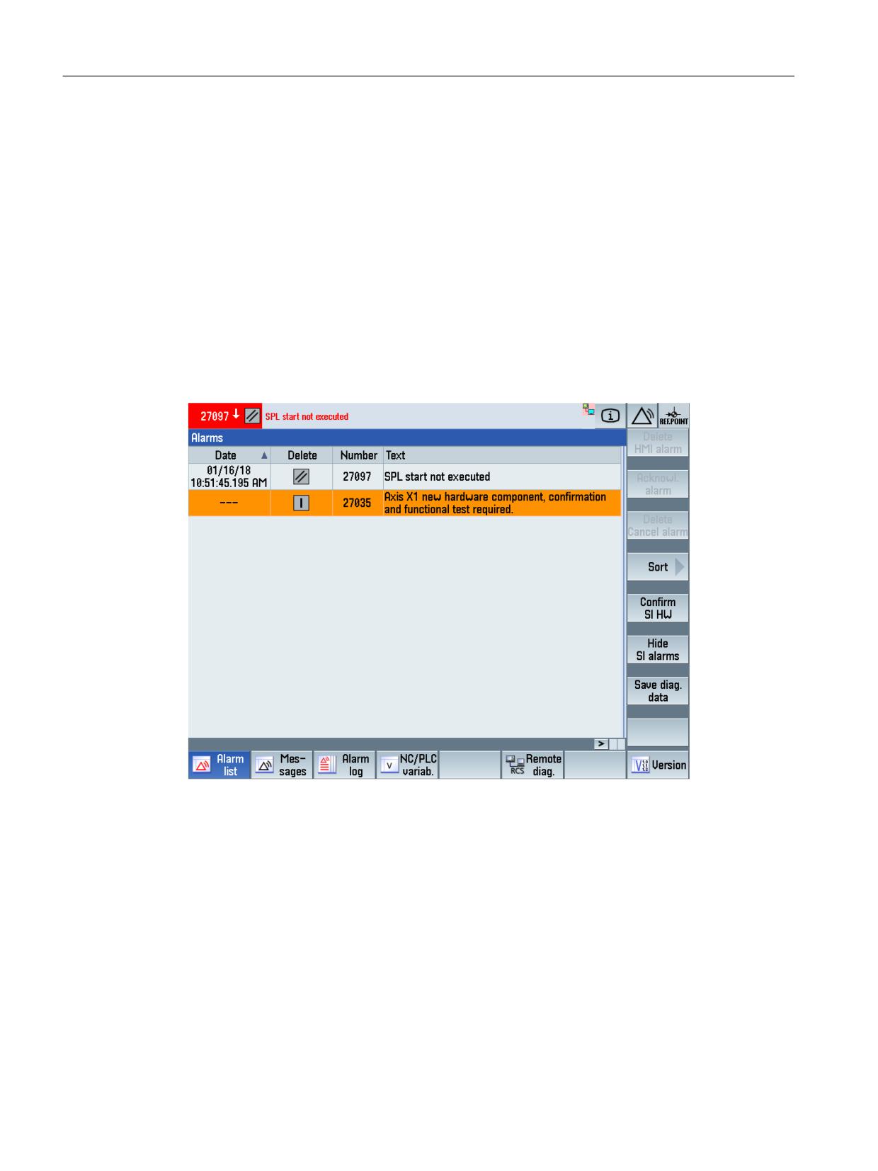
After at least one of these encoder components has been replaced, Alarm 27035 "Axis %1 new
HW component, acknowledgment and function test required" is output (changed CRC in index
1 of $MA_SAFE_ACT_CHECKSUM[ ] and possibly Alarm F01680 with ID 2, i.e. hardware IDs have
changed).
When replacing motors with integrated encoders, Alarm F01680 "SI Motion CU: Checksum error
safe monitoring functions" is output with fault value 2 (changed CRC of parameter p9728[2]),
i.e. changed hardware identifiers). Also in this case, an acknowledgment is required and a
function test must be performed.
The term "function test" designates a partial acceptance test that is described in detail in the
alarm description.
If Alarm 27035 or F01680 with ID 2 is output, a new softkey "Acknowledge SI HW" is displayed
in the alarm screen. This can only be actually selected with key switch setting 3 (the same as for
the user agreement).
Figure 10-16
Acknowledging SI HW
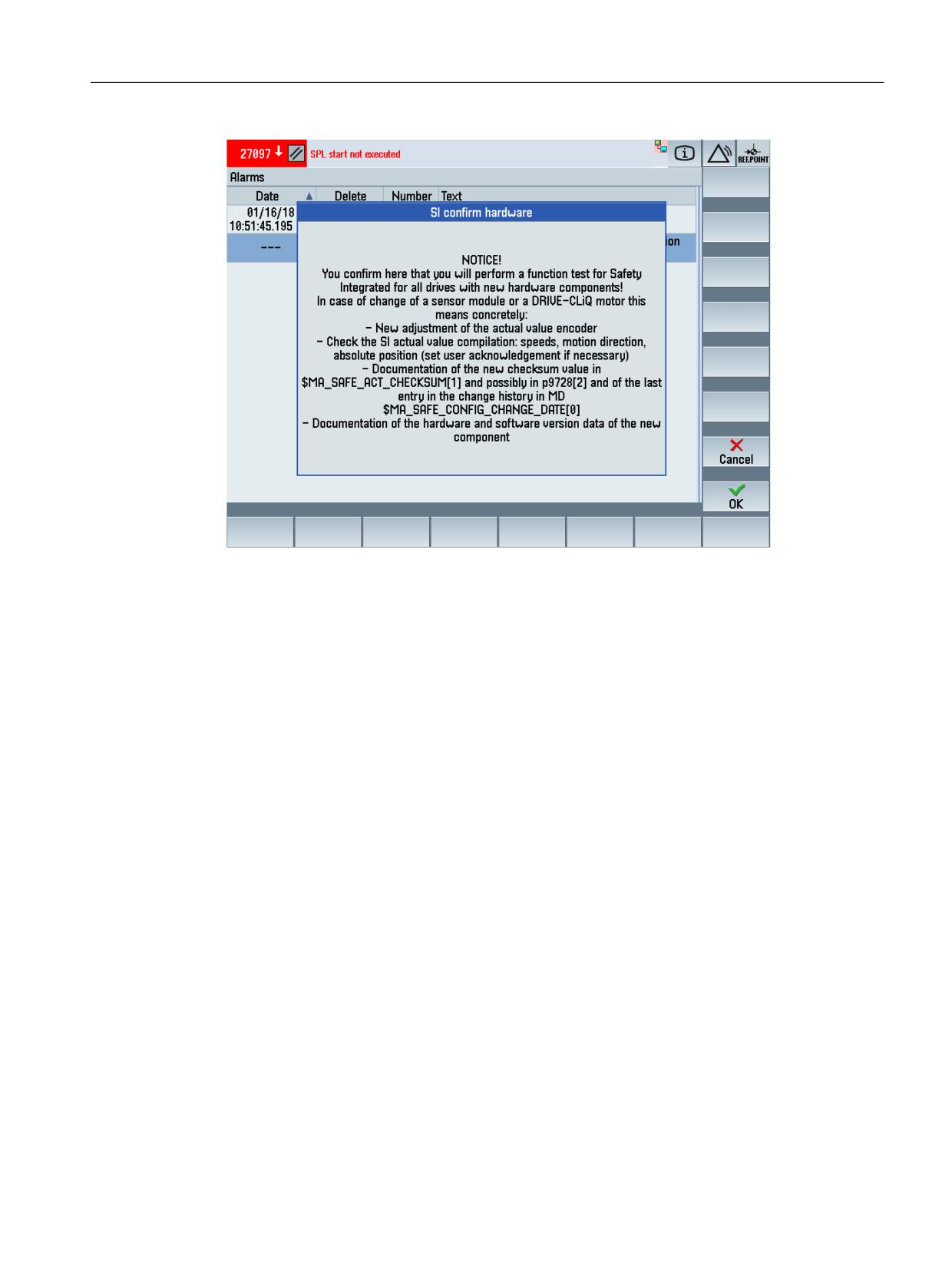
The following message is displayed after pressing softkey "Ackn. HW":
Safety Integrated (system-integrated)
556
Function Manual, 10/2020, 6FC5397-4BP40-6BA2
Commissioning
10.7 Replacing a motor or encoder
Figure 10-17
Acknowledging SI HW, step 2
After acknowledging with softkey "OK", the actual checksums SAFE_ACT_CHECKSUM[1] /
r9728[2] for all of the axes are copied to the reference checksum SAFE_DES_CHECKSUM[1] /
p9729[2] and a recommendation is given to power on the control. This is done by pressing the
"OK" softkey.
After the system has successfully booted, the user must carry out the measures of the function
test just acknowledged in the HMI messages or in Alarm 27035 / F01680, i.e.
• Re-calibration of the actual value encoder
• Checking the SI actual value acquisition: Speeds, traversing direction, absolute position (if
required, set the user agreement)
• Document the new checksum value in SAFE_ACT_CHECKSUM[1] or r9728[2] and the last
entry in the change history in MD SAFE_CONFIG_CHANGE_DATE[0]
• Document the hardware and software version data of the new component
Alternatively, Alarm 27035 / F01680 can be acknowledged using the softkey "Acknowledge SI
data" and the softkey "Reset drive/NCK".
The user can suppress the automated internal actual value check by resetting the "user
agreement" - therefore requesting that the axis is re-calibrated with the appropriate user
agreement.
Safety Integrated (system-integrated)
Function Manual, 10/2020, 6FC5397-4BP40-6BA2
557
Commissioning
10.7 Replacing a motor or encoder
10.7.1
Replacing a hardware component
General
For SINUMERIK controls with the Safety Integrated function, the safety-related hardware
components (e.g. SMI motors, SMC, SME) are secured using a checksum.
In the case of service, when replacing one of these components, the checksum for the hardware
component must be confirmed.
Up to SINUMERIK SW release 4.5, when replacing the components listed above, the
confirmation of the new checksum is supported by a softkey in the "Diagnostics" area ("SI
confirm HW data").
As a result of the extended features in the SINAMICS runtime software, in addition to the
hardware components (SMI motors, SMC SME), additional components are also monitored
(motor module, EnDat encoder).
Depending on the component being replaced, this is signaled to the user using Alarms
201640/201641
This feature is active in the default setting; by reconfiguring the message type, a response the
same as in SINUMERIK software releases > 4.7 can be re-established.
Acknowledging that a component has been replaced
Softkey "SI confirm HW data" in the Diagnostics/alarm list area supports acknowledging when a
component has been replaced.
Providing a response as in SINUMERIK software < 4.7
In order to provide you with a response applicable up to software release < 4.7, it is possible to
modify the message type of alarms 201640/201641 - and set to "No report".
To do this, you must set parameters p2118 and 2119 in the drive as follows:
• p2118[0...19] change message type message number
= alarm number (e.g. 1640)
• p2119[0...19] change message type, type
= 3: No message (N, "No Report")
Replacing components in conjunction with changeover heads
We recommend that alarms 201640/201641 are configured for "No Report" to provide a
changeover head scenario.
Otherwise, when changing a head, depending on the encoder type, one of the two following
alarms can be output.
Safety Integrated (system-integrated)
558
Function Manual, 10/2020, 6FC5397-4BP40-6BA2
Diagnostics
11
11.1
Troubleshooting procedure
• The alarms that have been activated in response to an error are output in the "DIAGNOSIS -
ALARMS" screen. When required, the safety alarms can be suppressed in the diagnostics
display using the "Filter out SI alarms" softkey.
• For Alarm 27090 "Error for crosswise Data comparison NCK-PLC", the cause of the error (the
incorrect SPL variable) is displayed in the alarm output.
• For Alarm 27254 "PROFIsafe: F-module, error on channel", the input/output channel with
error for modules belonging to the ET 200 series, is displayed in the alarm output.
• For Alarm 27001 "Defect in a monitoring channel", the fine error code is also displayed in the
alarm output.
• For Alarm C01711 "SI Motion defect in a monitoring channel" the fine error code is displayed
in the alarm output. The cause of the alarm can be read out in screen ”Commissioning -
Machine data - Drive MD” using parameter r9725 “SI Motion diagnostics STOP F”.
• The actual crosswise data comparison of the drive monitoring channel is displayed in
diagnostic screen "Status SI” - in line "STOP F code value".
• For Alarms F01611/F30611 "Defect in a monitoring channel", the fine error code is displayed
in the alarm output. The actual error search of this alarm is additionally displayed in
parameters r9795/r9895.
Note
Different error codes may be displayed for the NCK and drive monitoring channels.
Safety Integrated (system-integrated)
Function Manual, 10/2020, 6FC5397-4BP40-6BA2
559
Diagnostics
11.1 Troubleshooting procedure
11.1.1
Service displays
SINUMERIK Operate
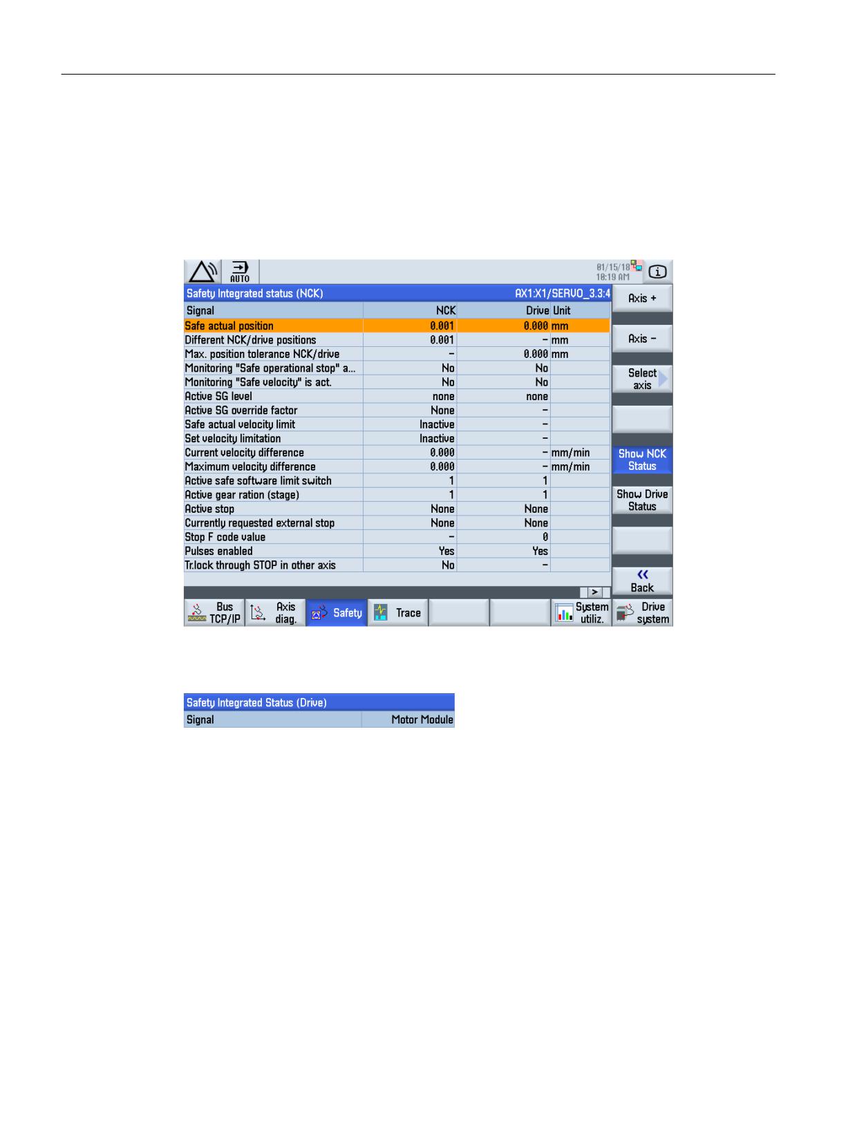
If safety functions are configured in the NCK as well as at the drive, softkeys "Display NCK status"
and "Display drive status" are available.
Figure 11-1
New softkeys to select the display for SI status
In the menu header line you can see whether you are in the NCK or in the drive.
Figure 11-2
SI header status
Safety Integrated (system-integrated)
560
Function Manual, 10/2020, 6FC5397-4BP40-6BA2
Diagnostics
11.1 Troubleshooting procedure
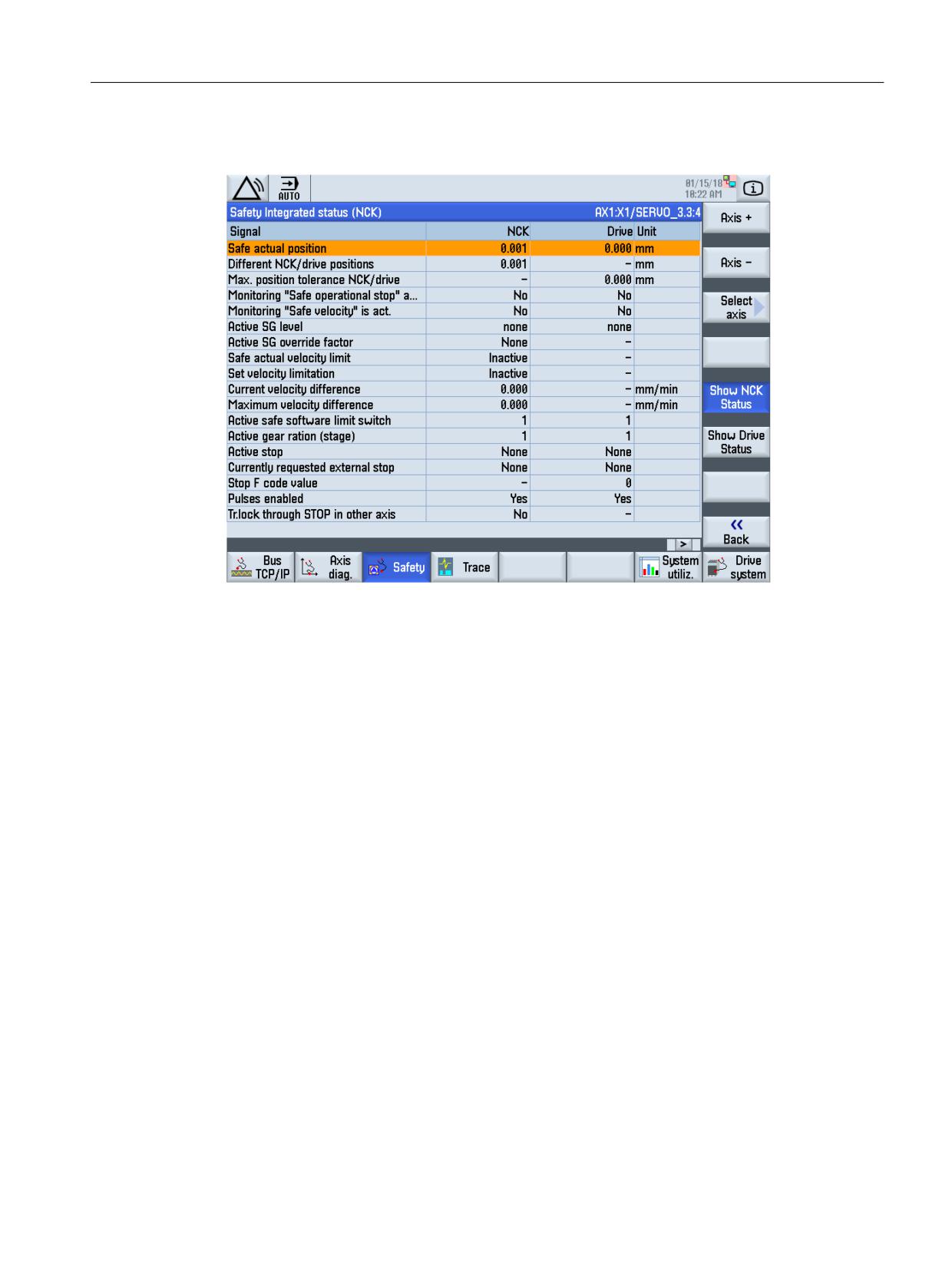
Display of the diagnostic signals of the NCK
Figure 11-3
Status display NCK
The "axis+", "axis-" vertical softkeys or "Direct selection" are used to set the required axis. The
actual axis is displayed in the top right half of the table header line.
Various states for both channels are displayed separately in the diagnostics screen.
Safety Integrated (system-integrated)
Function Manual, 10/2020, 6FC5397-4BP40-6BA2
561
Diagnostics
11.1 Troubleshooting procedure
Display of the diagnostic signals of the drive
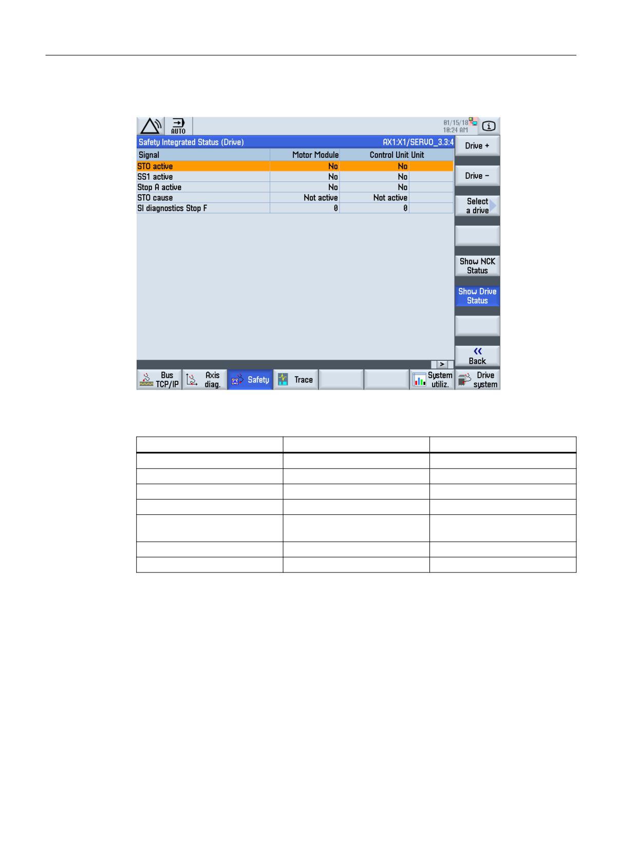
Figure 11-4
Status signals, drive
The following table shows the list of signals of the drive for the status SI screen.
Signal
Motor Module
Control Unit
STO active
r9872.1
r9772.1
SS1 active
r9872.2
r9772.2
STOP A active
r9872.10
r9772.10
STOP F active
r9872.15
r9772.15
STO cause, Safety commission-
r9872.16
r9772.16
ing mode
STO cause, selection via terminal
r9872.17
r9772.17
STO cause, actual value is missing
r9872.19
r9772.19
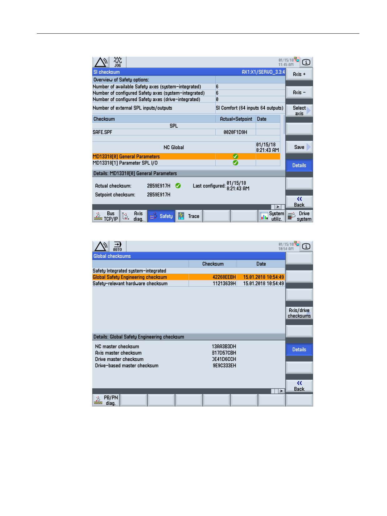
Display of the checksum
The screen for checksum SI is divided into three areas:
• Safety options
• Safety checksum status
• Details, safety checksums
Safety Integrated (system-integrated)
562
Function Manual, 10/2020, 6FC5397-4BP40-6BA2
Diagnostics
11.1 Troubleshooting procedure
Figure 11-5
Display of the checksum
Figure 11-6
Global checksum
• "Save" softkey
With this softkey, the values of the checksum for all drives and axes are saved in an XML file,
which is selected by the user.
• "Details" softkey
This softkey is used to select detailed information concerning the selected checksum.
Safety Integrated (system-integrated)
Function Manual, 10/2020, 6FC5397-4BP40-6BA2
563
Diagnostics
11.1 Troubleshooting procedure
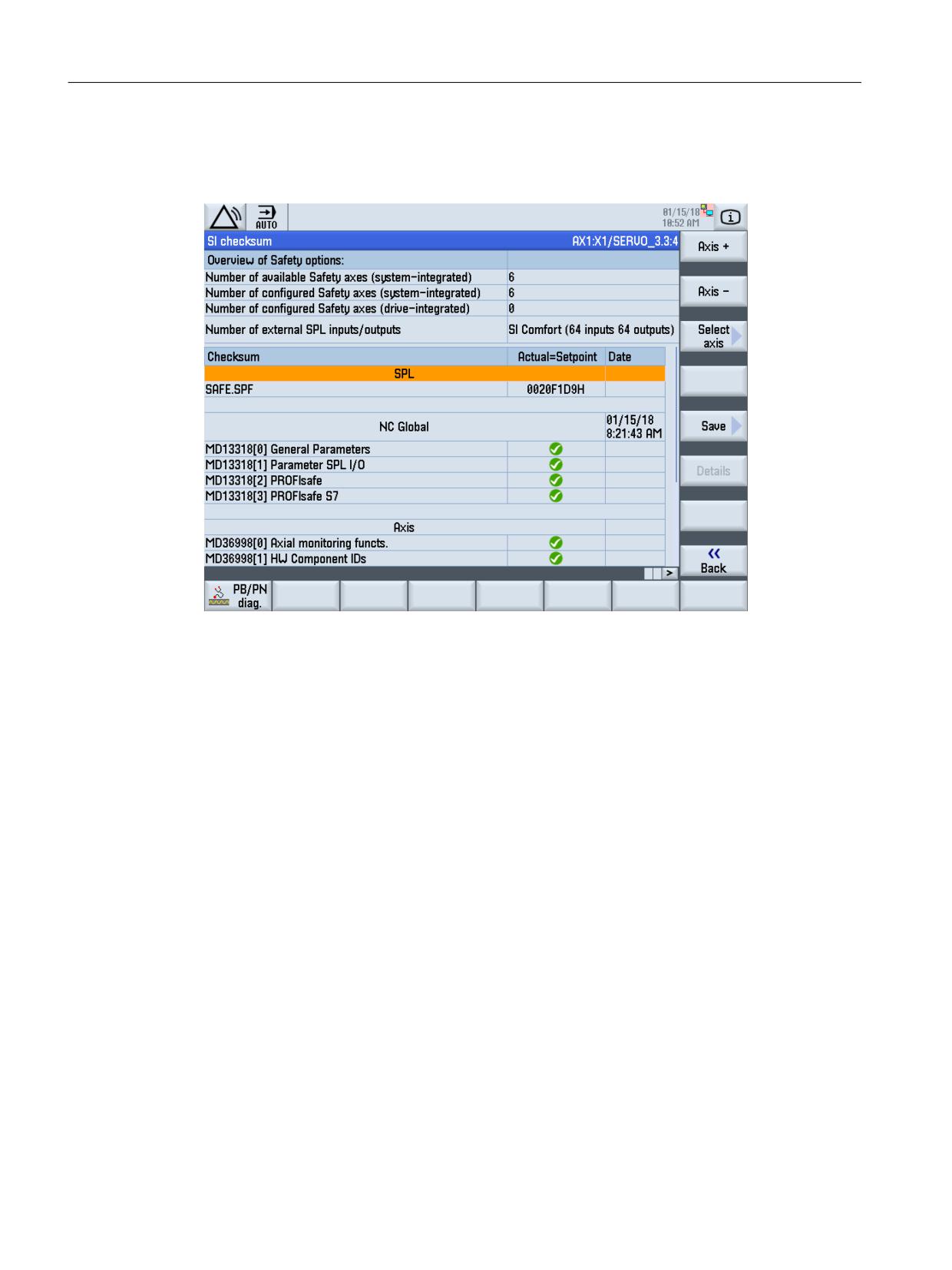
SI configuration
You can go to the SI configuration window by pressing the softkey "SI configuration".
Figure 11-7
SI configuration
An overview of the safety options that have been set is displayed in the upper section of this
diagnostics screen.
The Safety checksums for the NCK, the axis and the drive are shown in the lower window section.
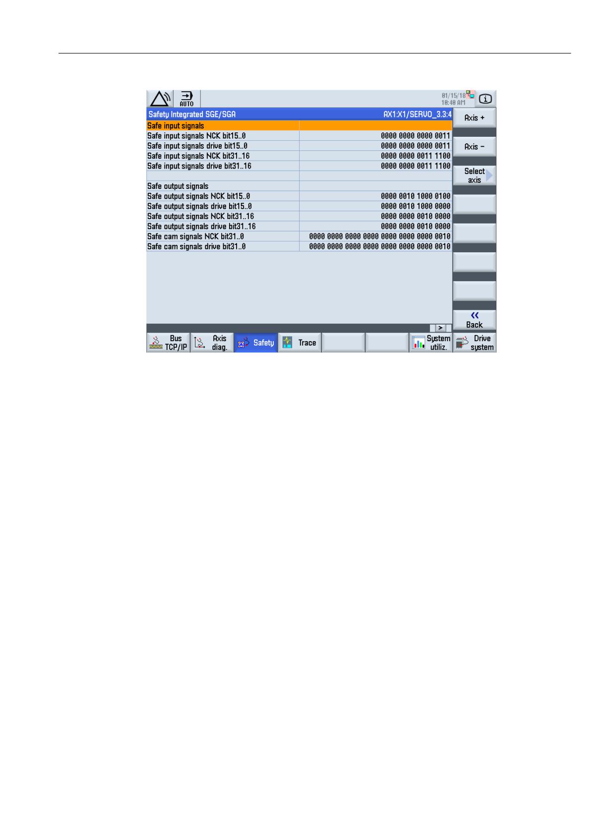
SGE/SGA
You can access the menu for the safety-related input and output signals using the "SGE/SGA"
softkey.
Safety Integrated (system-integrated)
564
Function Manual, 10/2020, 6FC5397-4BP40-6BA2
Diagnostics
11.1 Troubleshooting procedure
Figure 11-8
Status display of SGE/SGA
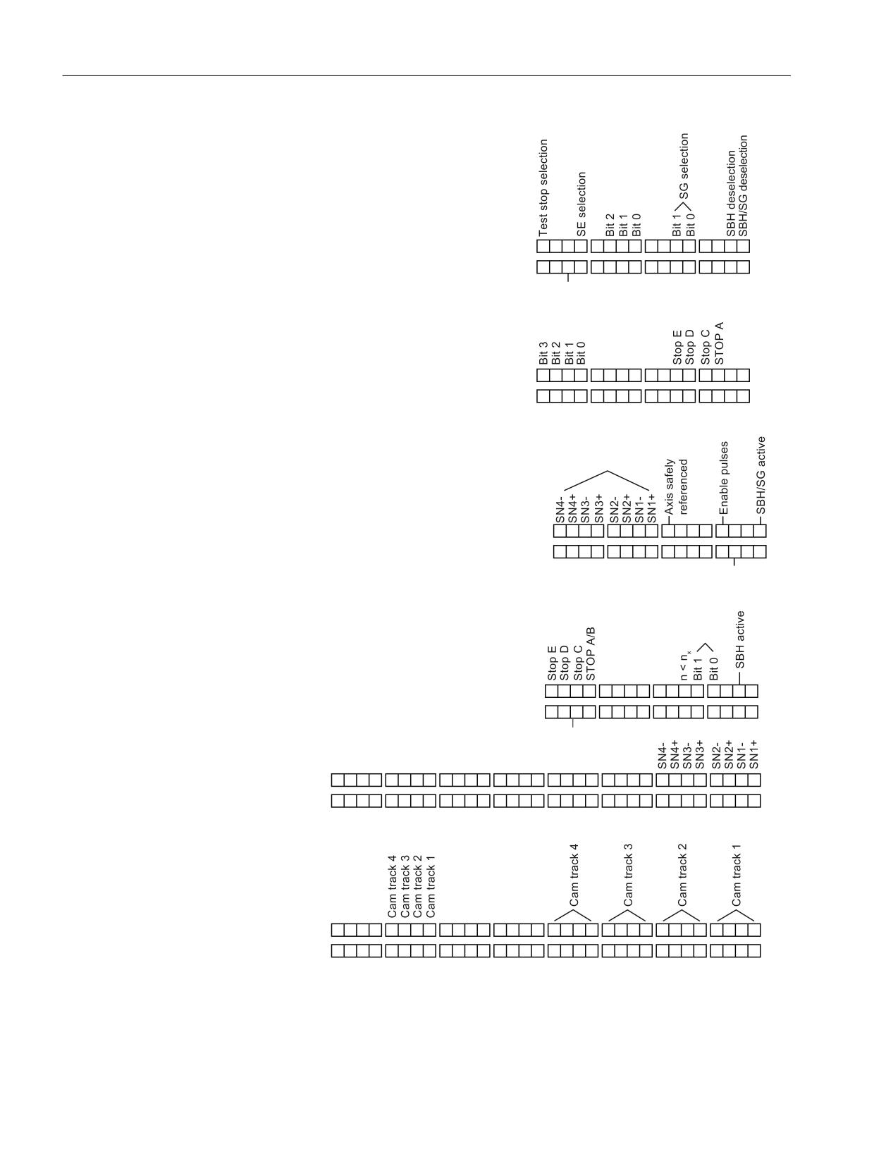
The available signals are shown in the diagram above.
The following diagram shows the detailed status display of the safety-related input and output
signals.
Safety Integrated (system-integrated)
Function Manual, 10/2020, 6FC5397-4BP40-6BA2
565
Diagnostics
11.1 Troubleshooting procedure
$[LV
1&. PRQLWRULQJ FKDQQHO
'ULYH
'ULYH PRQLWRULQJ FKDQQHO
5DWLR VHOHFWLRQ
%LW
6DIH LQSXW VLJQDOV D[LV
6DIH LQSXW VLJQDOV GULYH
&ORVH EUDNH
'HVHOHFW H[W
VWRS
6* FRUU
%LW
6DIH LQSXW VLJQDOV D[LV
6DIH LQSXW VLJQDOV GULYH
%LW
6DIH RXWSXW VLJQDOV D[LV
6DIH RXWSXW VLJQDOV GULYH
RQO\ LI WKH 6DIH &DP IXQFWLRQ LV DFWLYH
6WDWXV SXOVHV
DUH FDQFHOOHG
$FWLYH VWRS
6* DFWLYH
%LW
6DIH RXWSXW VLJQDOV D[LV
6DIH RXWSXW VLJQDOV RI WKH GULYH
;
6DIH &DP IXQFWLRQ DFWLYH
%LW
6*$ D[LV
6*$ GULYH
$[LV LV ORFDWHG RQ WKH FDP RI WKH
DFWLYH FDP UDQJH IRU
6DIH &DP 7UDFN IXQFWLRQ
DFWLYH
%LW
6*$ D[LV
6*$ GULYH
Figure 11-9
Significance of the status display of the safety-related input and output signals
Safety Integrated (system-integrated)
566
Function Manual, 10/2020, 6FC5397-4BP40-6BA2
Diagnostics
11.1 Troubleshooting procedure
Cam SGA
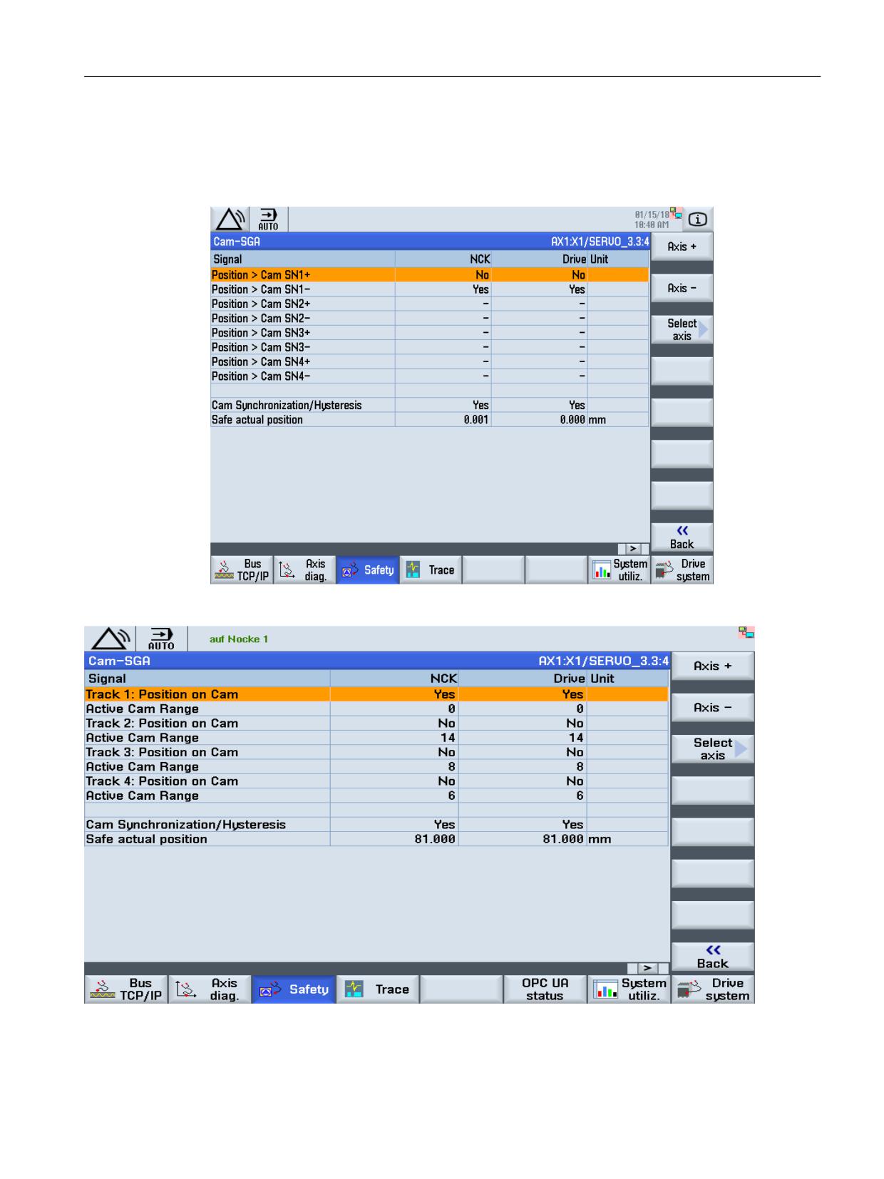
You can access the corresponding menu for Safe Cam or Safe Cam Track access using the "Cam
SGA" softkey.
Figure 11-10
Safe Cams
Figure 11-11
Safe Cam Track
Safety Integrated (system-integrated)
Function Manual, 10/2020, 6FC5397-4BP40-6BA2
567
Diagnostics
11.1 Troubleshooting procedure
SPL
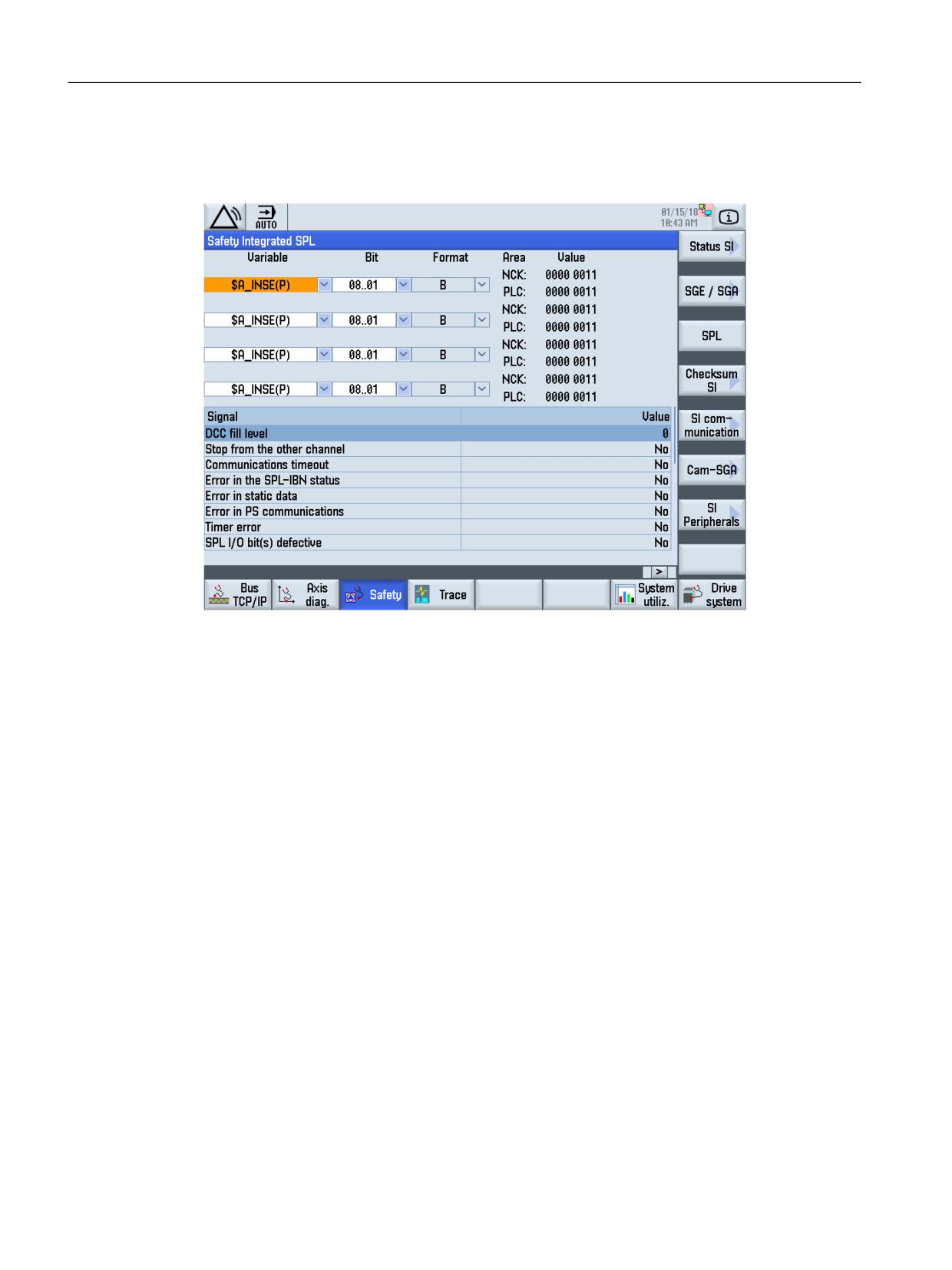
The softkey "SPL" is used to access the window for the status display of the SPL.
Figure 11-12
Status display SPL
In the "Variable" selection box, you can select:
$A_INSE(P) corresponds to simultaneous selection of
$A_INSE upper line, origin of the NCK and
$A_INSEP lower line, origin of the PLC
and essentially in the same way for the other variables:
$A_OUTSE(P)
$A_INSI(P)
$A_OUTSI(P)
$A_MARKERSI(P)
$A_PLCSIIN
$A_PLCSIOUT
The variables that have been selected and the associated bit areas are saved and are taken into
account when subsequently selecting the screen.
Using the select key, the following formats can be selected in the variable rows
B binary
H hexadecimal
D decimal.
Safety Integrated (system-integrated)
568
Function Manual, 10/2020, 6FC5397-4BP40-6BA2
Diagnostics
11.1 Troubleshooting procedure
The selected format is applicable for the particular variable, as each variable can be assigned an
individual display format.
Further, various SPL states are displayed.
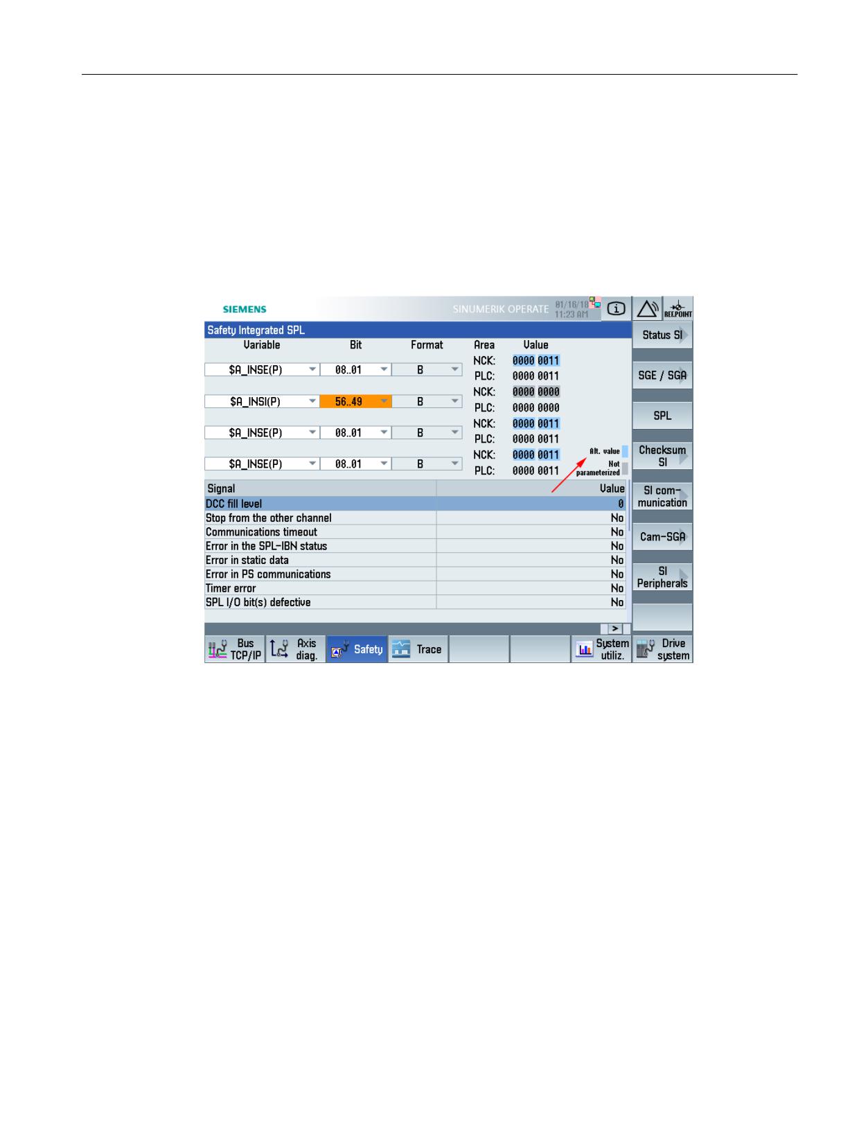
Displaying the qualities of SPL input/output variables
Just displaying values "0" and "1" in the diagnostics screen is not sufficient to identify the cause
of faults that have occurred. For a more precise evaluation, the quality of these two values is of
interest.
Figure 11-13
Display of the quality
The following colors are used to display the quality:
=
"Process value": the actual value of the system variables (0 or 1) represents a
process value.
Light blue
"Substitute value": the actual value of the system variables (0 or 1) represents a
(static or dynamic) substitute value; i.e. is currently not supplied with a process
value from one of the known sources.
Gray
"Not parameterized": the system variable (value 0 or 1) is, as a result of the MD
parameterization, not assigned to the known sources/sinks.
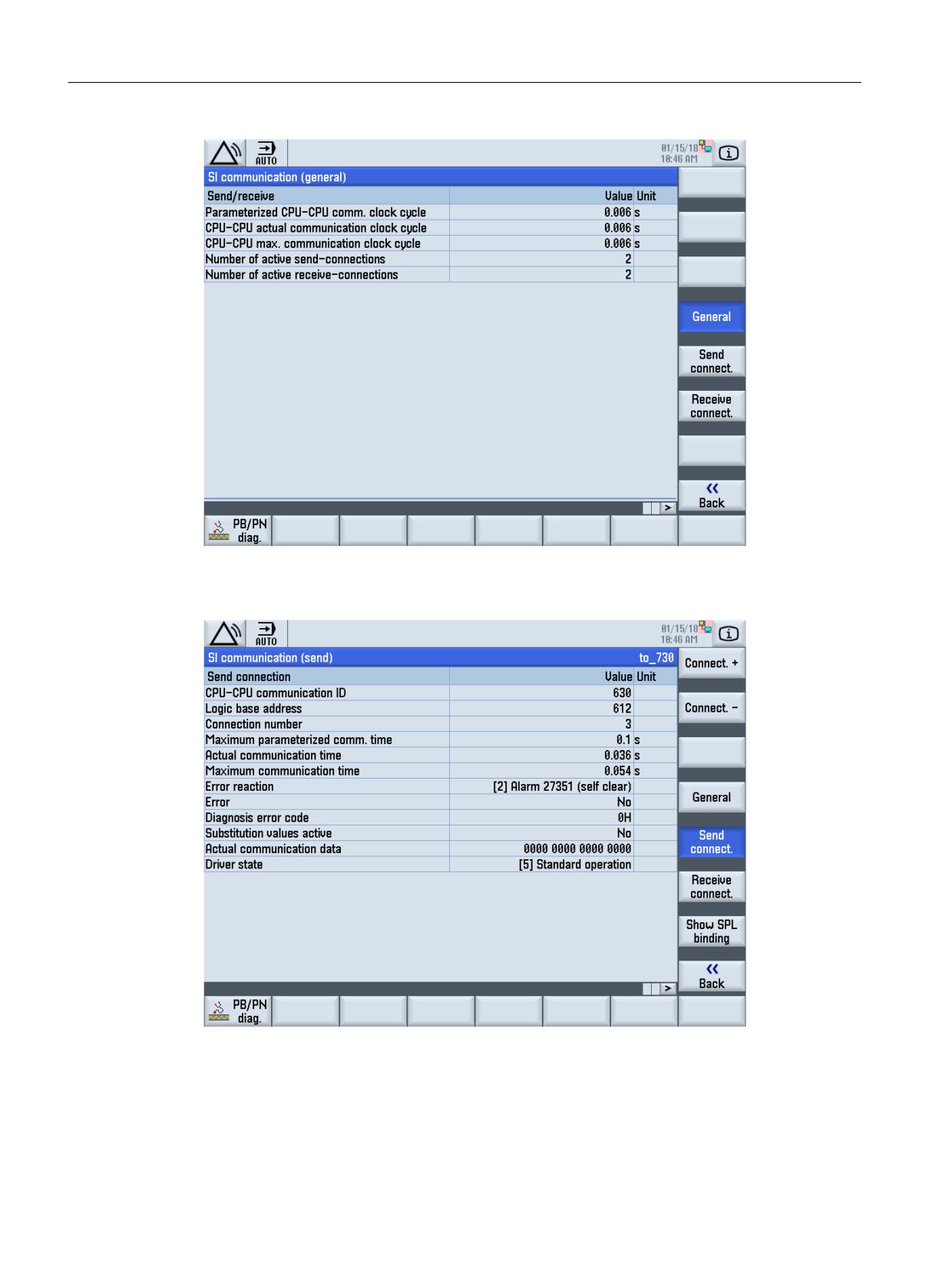
SI communication
You can access the menu of the SI communication using the "SI communication" softkey.
Safety Integrated (system-integrated)
Function Manual, 10/2020, 6FC5397-4BP40-6BA2
569
Diagnostics
11.1 Troubleshooting procedure
Figure 11-14
Status display SI communication
The send and receive connections can be selected using the vertical softkeys.
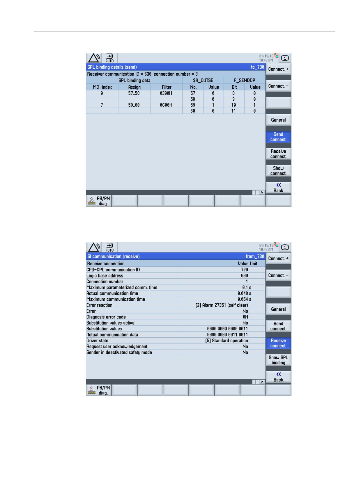
Figure 11-15
SI communication (send)
The SI communication (send) menu contains a list of the configuration in tabular form and the
status of the send connection (F_SENDDP). Additional details, e.g. the comparison of the
$A_OUTSE variables and F_SENDDP are displayed using the softkey "Display SPL couplings".
Safety Integrated (system-integrated)
570
Function Manual, 10/2020, 6FC5397-4BP40-6BA2
Diagnostics
11.1 Troubleshooting procedure
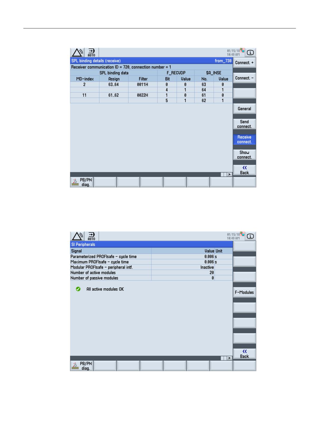
Figure 11-16
SPL coupling (sending)
Data for F_RECVDP are displayed using the "Receive connection" softkey and "Display SPL
couplings".
Figure 11-17
SI communication (receive)
Safety Integrated (system-integrated)
Function Manual, 10/2020, 6FC5397-4BP40-6BA2
571
Diagnostics
11.1 Troubleshooting procedure
Figure 11-18
SPL coupling (receiving)
SI I/O
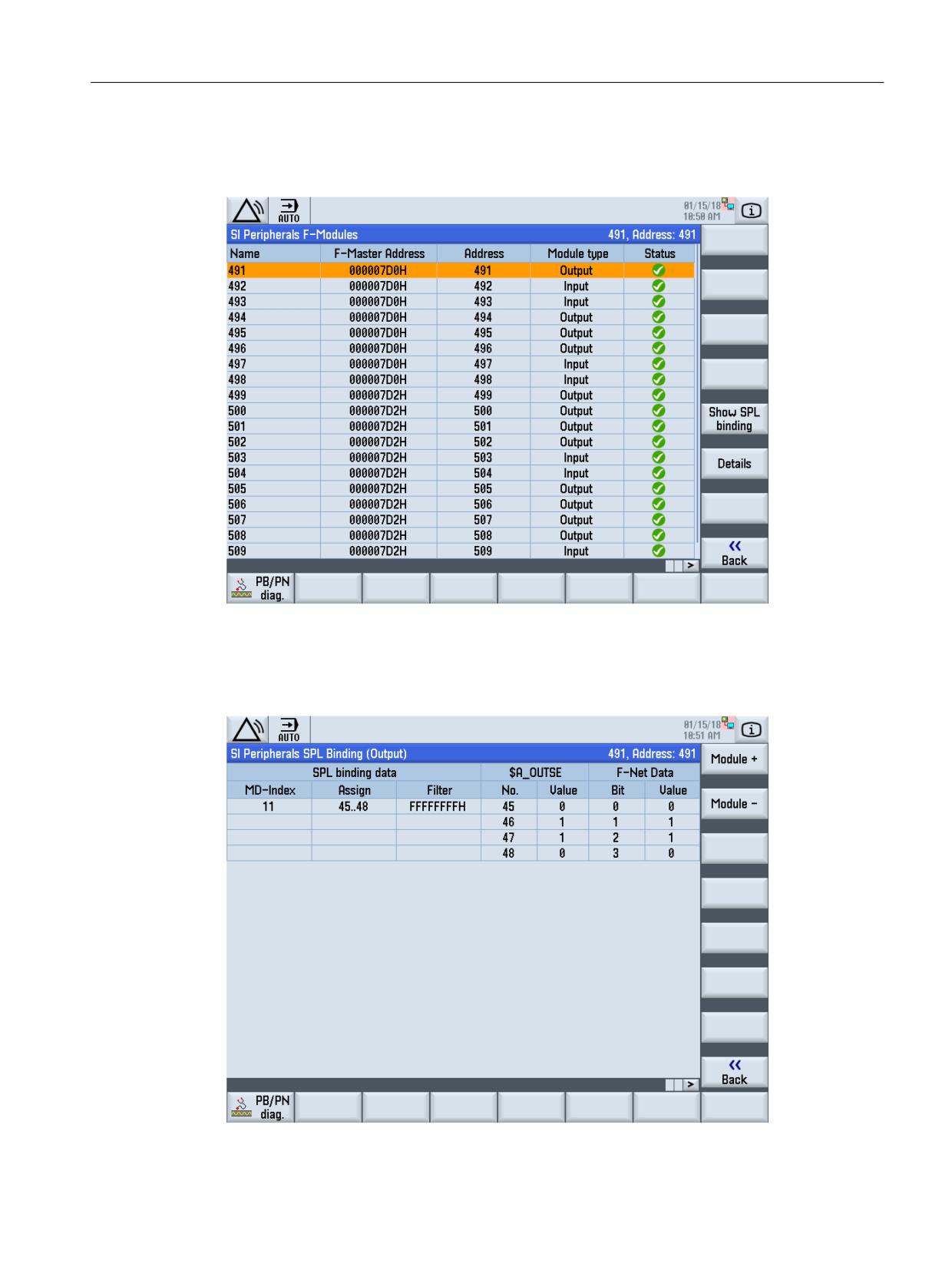
If, in the status display (Fig. "Status display NCK"), the "SI I/O" softkey is pressed, then you obtain
a general overview of the parameterized PROFIsafe communication:
Figure 11-19
SI I/O
Safety Integrated (system-integrated)
572
Function Manual, 10/2020, 6FC5397-4BP40-6BA2
Diagnostics
11.1 Troubleshooting procedure
By pressing the "F-modules" softkey, all of the parameterized F-modules are displayed together
with the master address, PROFIsafe address, module type with the actual status.
Figure 11-20
SI I/O F-modules
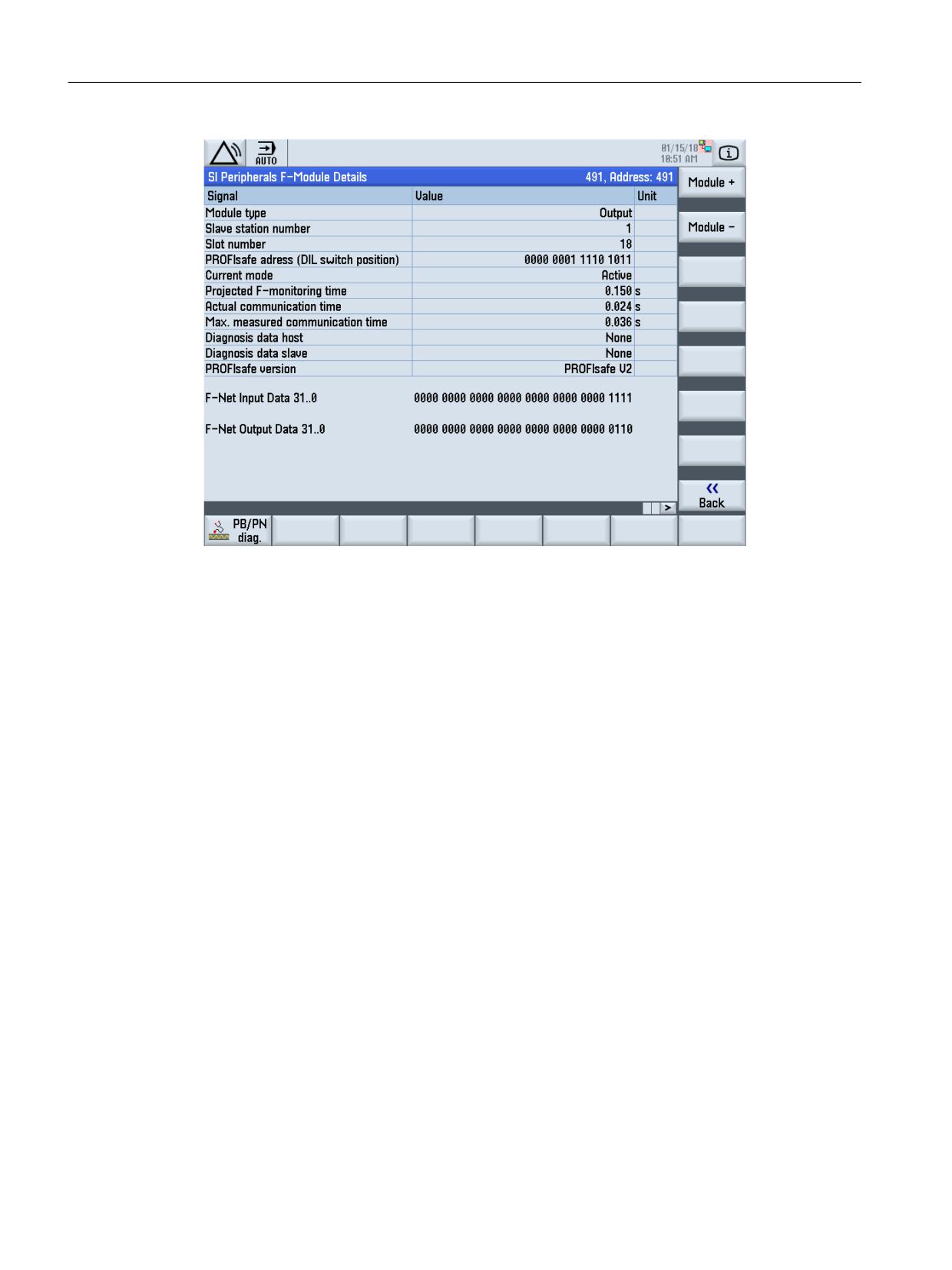
Using the "Display SPL connection" softkey, the parameterized assignment of the F-module to
the SPL is displayed with the actual data. You can toggle between the modules using the "Module
+" and "Module -" softkeys.
Figure 11-21
SPL coupling of the SI-I/O
Safety Integrated (system-integrated)
Function Manual, 10/2020, 6FC5397-4BP40-6BA2
573
Diagnostics
11.1 Troubleshooting procedure
Figure 11-22
Details of the F-modules
11.1.2
Safety Integrated global checksums
The number of checksums to be checked at a machine is reduced through the introduction of
master checksums.
All of the checksums of an axis - or also all axes - are added in these master checksums. This
means that users only have to compare one checksum in order to check whether something has
changed since the last time it was determined. As a consequence, the master checksum is not
saved, but when required, is recalculated each time.
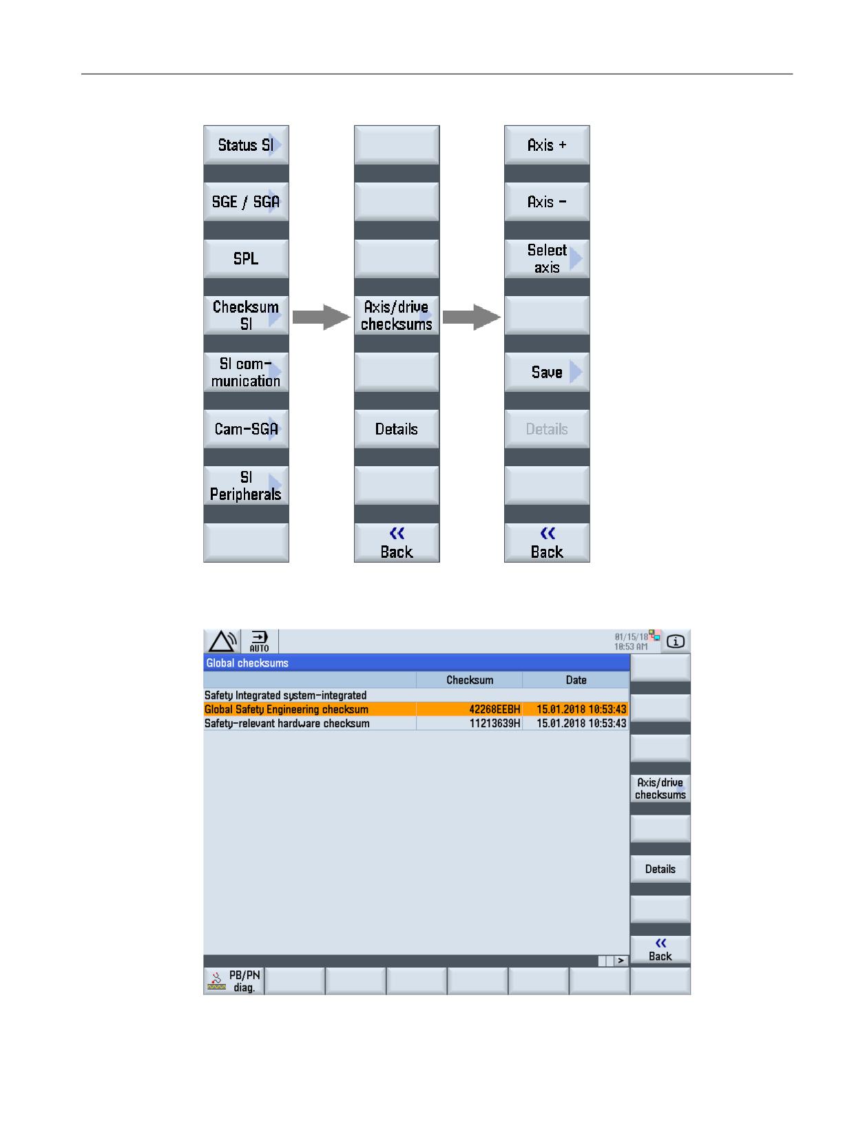
The global checksums for Safety Integrated are shown in the Diagnostics operating area as
dedicated dialog in the existing checksums screen. The global checksums are determined and
the dialog is displayed by pressing the "Checksum SI" vertical softkey. The previous SI checksum
dialog is kept, and can be accessed from the "Global checksum" dialog by pressing vertical
softkey "Axis/drive checksum". (For a comparison, see diagram, "Status SI").
The navigation branches as follows:
Safety Integrated (system-integrated)
574
Function Manual, 10/2020, 6FC5397-4BP40-6BA2
Diagnostics
11.1 Troubleshooting procedure
Figure 11-23
Softkey bar for safety diagnostics, global checksums, SI checksum
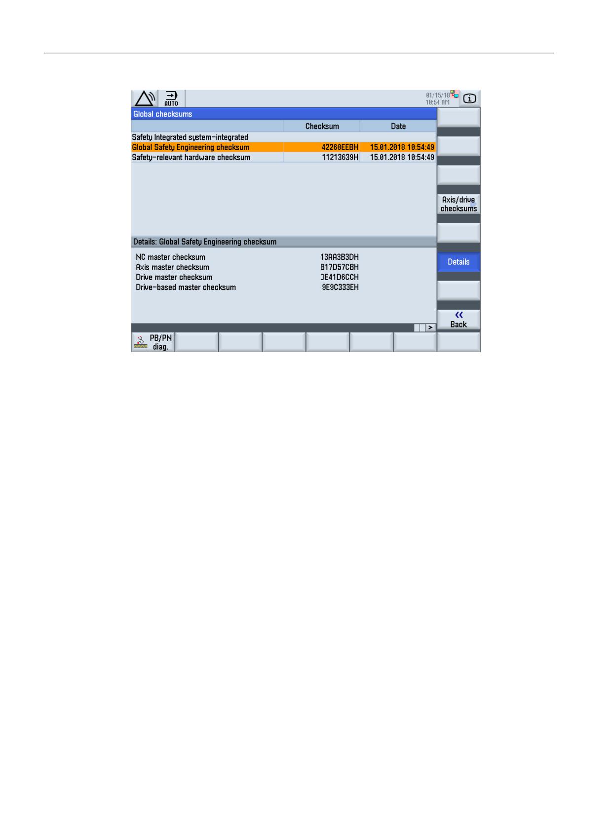
The following dialog is displayed with softkey "Checksum SI"
Figure 11-24
SI global checksums
Safety Integrated (system-integrated)
Function Manual, 10/2020, 6FC5397-4BP40-6BA2
575
Diagnostics
11.1 Troubleshooting procedure
Figure 11-25
SI checksum
A table is displayed in which the global checksums are listed with the calculation date.
When the dialog is first displayed, the cursor is positioned at the first line with a checksum. The
cursor is only positioned to lines that contain a checksum.
Safety Integrated (system-integrated)
576
Function Manual, 10/2020, 6FC5397-4BP40-6BA2

Diagnostics
11.1 Troubleshooting procedure
The global checksums are calculated as follows:
Master checksum
Calculated by adding the listed data
Global safety engineer-
NC master checksum
SAFE.SPF checksum
ing checksum
$MN_SAFE_GLOB_ACT_CHECKSUM[0]
(sum of all master check-
$MN_SAFE_GLOB_ACT_CHECKSUM[1]
sums)
$MN_SAFE_GLOB_ACT_CHECKSUM[2]
$MN_SAFE_GLOB_ACT_CHECKSUM[3]
Axis master checksum
$MA_SAFE_ACT_CHECKSUM[0]
$MA_SAFE_ACT_CHECKSUM[2]
(Sum across all axes with $MA_SAFE_FUNCTION_ENA-
BLE.0==1)
Drive master checksum
r9728[0]
r9728[1]
(Sum across all drives, that are assigned to an axis with
$MA_SAFE_FUNCTION_ENABLE.0==1)
Drive-based master checksum
r9798
r9898
(sum across all drives, which are assigned to one axis with
$MA_SAFE_FUNCTION_ENABLE.0==1)
Safety-relevant hardware
Safety-relevant hardware checksum
$MA_SAFE_ACT_CHECKSUM[1]
checksum
(Sum across all axes with $MA_SAFE_FUNCTION_ENABLE
0==1)
r9728[2]
(Sum across all drives, that are assigned to an axis with
$MA_SAFE_FUNCTION_ENABLE.0==1)
Data are determined and the checksums are calculated when the dialog is displayed.
The calculation of the checksums depends on the expansion stage of the control system and can
take longer than 10 seconds. During the calculation, a progress bar is displayed, which indicates
which global checksums are presently being calculated and which MD or parameters are
presently being read from which axis or which drive object.
The progress dialog can be exited using the "Cancel" softkey which then also means that the
calculation of the checksums is canceled. The global checksums dialog remains empty and the
following text appears in the dialog window:
"No data can be displayed, as the calculation of the global checksums has been aborted". A new
calculation of the global checksums is realized with the "Display new" softkey.
The "Display new" softkey is only displayed if the calculation of the global checksums was
canceled. In this case, the "Details" softkey is also inactive.
The checksums are calculated across all SI for which the following applies: MD36901
$MA_SAFE_FUNCTION_ENABLE, bit 0 == 1. If there is no axis for system-integrated operation,
the "Safety Integrated system integrated" part in the table is omitted.
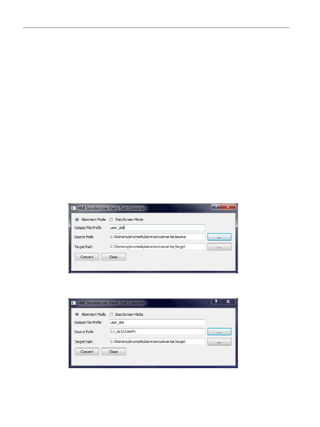
Master checksums are displayed using the "Details" softkey.
The Details dialog is updated with the cursor keys up and down. The cursor can only be
positioned to lines that contain a checksum.
Safety Integrated (system-integrated)
Function Manual, 10/2020, 6FC5397-4BP40-6BA2
577
Diagnostics
11.1 Troubleshooting procedure
The safety-relevant hardware checksum has only one master checksum. In the Details menu,
only one line is displayed with this checksum.
Using the "Back" softkey, you can change to the vertical softkey bar of the Safety diagnostics.
11.1.3
Integrating safety SPL user alarms
Preconditions
In order to integrate the alarm text extension for SINUMERIK Operate, the "HMI Solutionline
Alarm Text Converter" is used. Using this converter, it is possible to convert alarm text
extensions, which were already generated on an HMI Advanced or a self-generated alarm text
extension (in the *.com format) into the *.ts format required for SINUMERIK Operate, and to
integrate this using WINSCP.
The alarm text converter is included in the scope of delivery of the software
(setup_alarmtextconverter.exe).
Converting SINUMERIK Operate Safety user alarms from PCU50
Start the alarm text converter and allocate a filename under "Output File Prefix" (e.g. user_alsi).
Figure 11-26
Allocating the file name
The source directory is specified in "Source Path".
Figure 11-27
Selecting the source directory
Safety Integrated (system-integrated)
578
Function Manual, 10/2020, 6FC5397-4BP40-6BA2
Diagnostics
11.1 Troubleshooting procedure
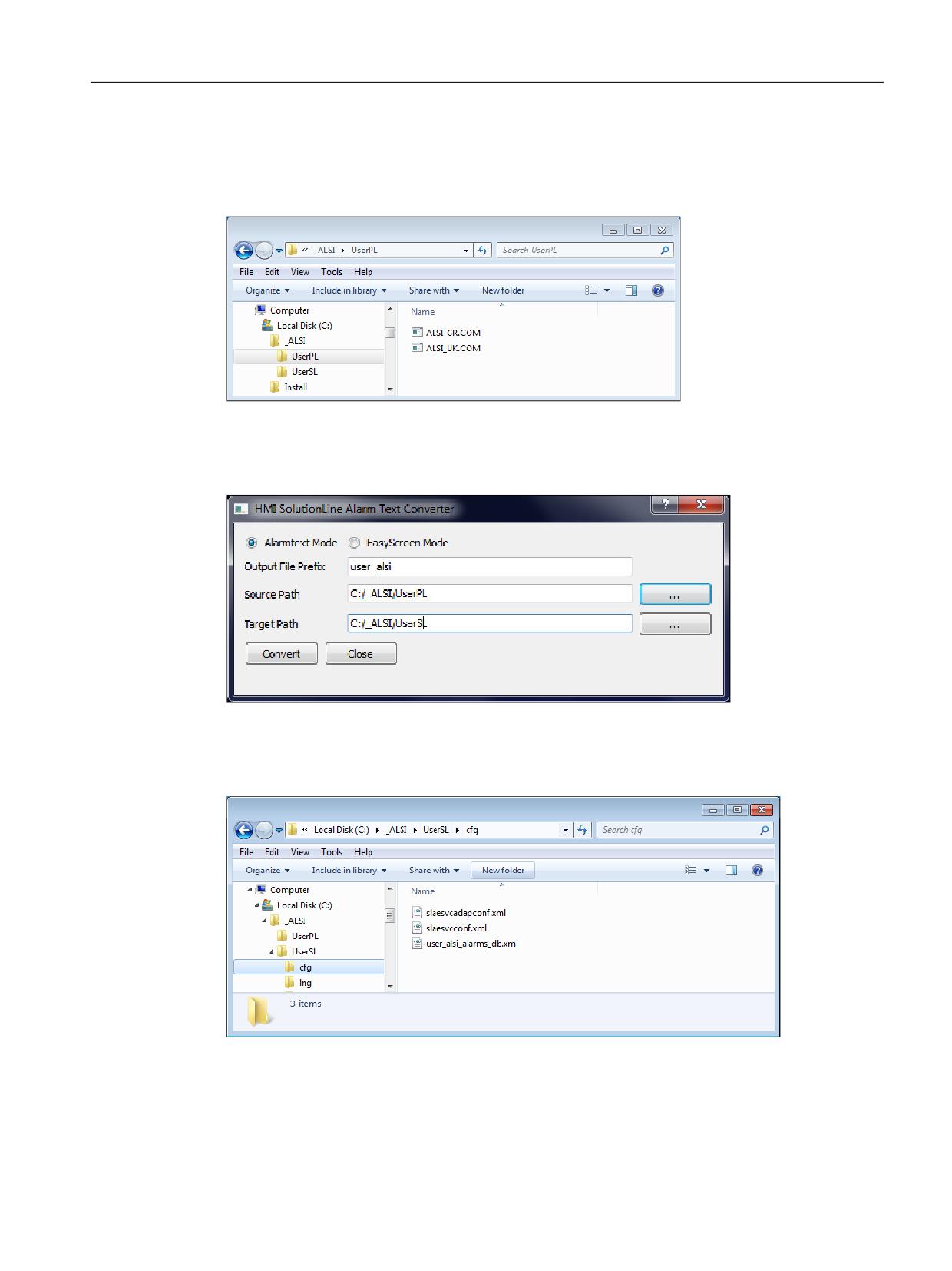
As the SPL user text files are index text files (pro rata alarm text), for correct conversion in the
specified "Source Path", a subdirectory with the name */ALSI must be created. The alarm text
extension file *.com to be converted must be saved in this subdirectory.
Figure 11-28
Creating a subdirectory
In "Target Path", the target directory is specified in which the converted safety user alarm text
files for SINUMERIK Operate should be stored.
Figure 11-29
Determining the target directory
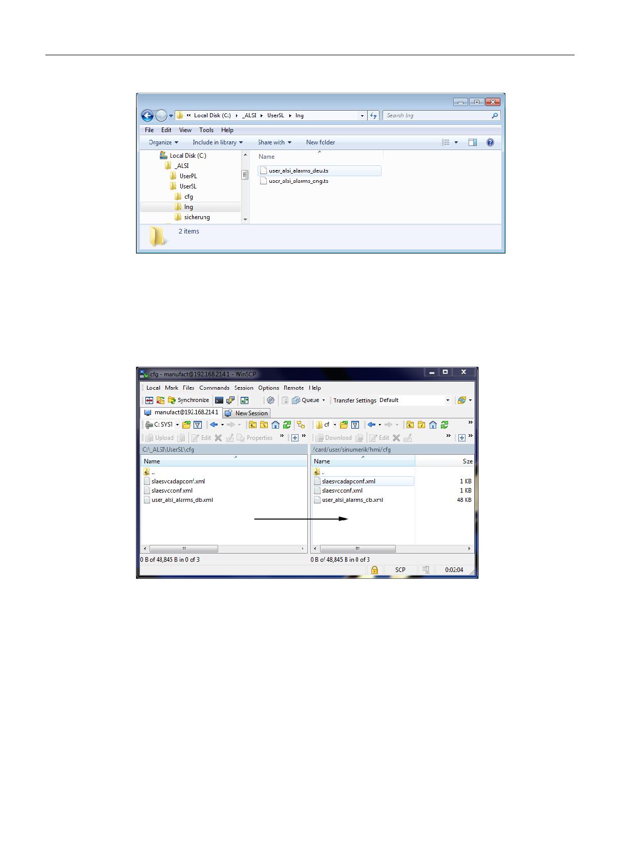
A "cfg" and an "Ing" folder are created in the "Target Path" with "Convert". The following files are
generated in "cfg":
Figure 11-30
Generating files in "cfg"
Safety Integrated (system-integrated)
Function Manual, 10/2020, 6FC5397-4BP40-6BA2
579
Diagnostics
11.1 Troubleshooting procedure
Figure 11-31
Generating files in "lng"
Depending on the language, the SI user alarm files are generated in "Ing":
Using WinSCP, the files/directories are copied to card/user/sinumerik/hmi/cfg respectively, card/
user/sinumerik/hmi/lng - or card/oem/sinumerik/hmi/cfg respectively, card/oem/sinumerik/hmi/
lng.
These files must now be copied to the card using WINSCP:
Figure 11-32
Copying the files into the user directory using WinSCP
If files with the same name already exist on the CF card, then the contents of the generated files
should be supplemented in the already existing ones. Additional information on this is provided
in the readme.txt in the installation path of the alarm text converter.
Safety Integrated (system-integrated)
580
Function Manual, 10/2020, 6FC5397-4BP40-6BA2
Diagnostics
11.1 Troubleshooting procedure
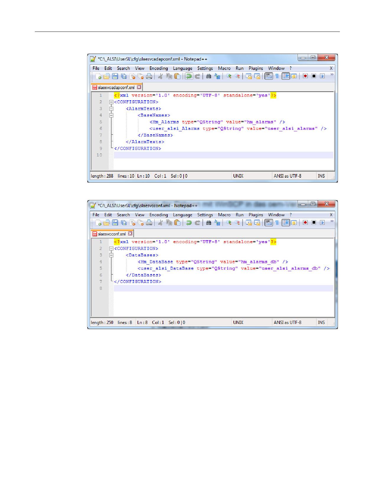
Figure 11-33
Extending slaesvcadapconf.xml
Figure 11-34
Extending slaesvcconf.xml
Generating, converting, and integrating SINUMERIK Operate safety user alarms COM files
Generating language-dependent COM files and converting into *.ts files
If there are no HMI Advanced files available, *.com files can be generated and converted into
files in the SINUMERIK Operate format using the "HMI solutionline alarm text converter".
Example of a syntax of a language-dependent *.com. File (e.g. alsi_gr.com / alsi_uk.com).
// Text extension for Alarms 27090 / 27254
;%4 = 000 error SPL protection (DB18.DBX36.0 / MD11500)
;%4 = 001...064: Error in system variables $A_INSE[01...64]
Safety Integrated (system-integrated)
Function Manual, 10/2020, 6FC5397-4BP40-6BA2
581
Diagnostics
11.1 Troubleshooting procedure
;%4 = 065...128: Error in system variables $A_OUTSE[01...64]
;%4 = 129...192: Error in system variables $A_INSI[01...64]
;%4 = 193...256: Error in system variables $A_OUTSI[01...64]
;%4 = 257...320: Error in system variables $A_MARKERSI[01...64]
; SPL protection
000000 0 0 "User text for Safety--SPL--commissioning--status (DB18.DBX36.0) / MD11500”
;
000001 0 0 ”User text for INSE(P)01”
000002 0 0 "User text for INSE(P)02"
000063 0 0 "User text for INSE(P)63"
000064 0 0 "User text for INSE(P)64"
000065 0 0 "User text for OUTSE(P)01"
000066 0 0 "User text for OUTSE(P)02”
000127 0 0 "User text for OUTSE(P)63"
000128 0 0 "User text for OUTSE(P)64"
000129 0 0 "User text for OUTSE(P)01"
000130 0 0 "User text for OUTSE(P)02"
000191 0 0 "User text for INSI(P)63"
000192 0 0 "User text for INSI(P)64"
000193 0 0 "User text for OUTSE(P)01"
000194 0 0 "User text for OUTSE(P)02"
000255 0 0 "User text for OUTSI(P)63"
000256 0 0 "User text for OUTSI(P)64"
000257 0 0 "User text for MARKERSI(P)01”
000258 0 0 "User text for MARKERSI(P)02”
000319 0 0 "User text for MARKERSI(P)63"
000320 0 0 "User text for MARKERSI(P)64"
If the *.COM files have been generated, then the SINUMERIK Operate files can be converted as
described above.
Safety Integrated (system-integrated)
582
Function Manual, 10/2020, 6FC5397-4BP40-6BA2
Diagnostics
11.1 Troubleshooting procedure
11.1.4
Trace bit graphics for Safety Integrated
General
The trace function is one of the measuring functions in the Diagnostics operating area. Using the
trace, for drive signals and NCK signals, measurements can be started by entering a measuring
time and trigger conditions. The results of the measurements are then graphically displayed.
The following variables are of interest:
• Trace for NC/PLC variables
Recording and graphical representation of the SERVO signal values with respect to time, such
as actual position value, following error, etc.
• Trace for drive variables
Recording and graphical representation of the signal values with respect to time from the
drive system, such as e.g. speed actual value, current actual value etc.
It must be possible for the signals to be recorded to be interconnected via a BICO source.
Starting the trace
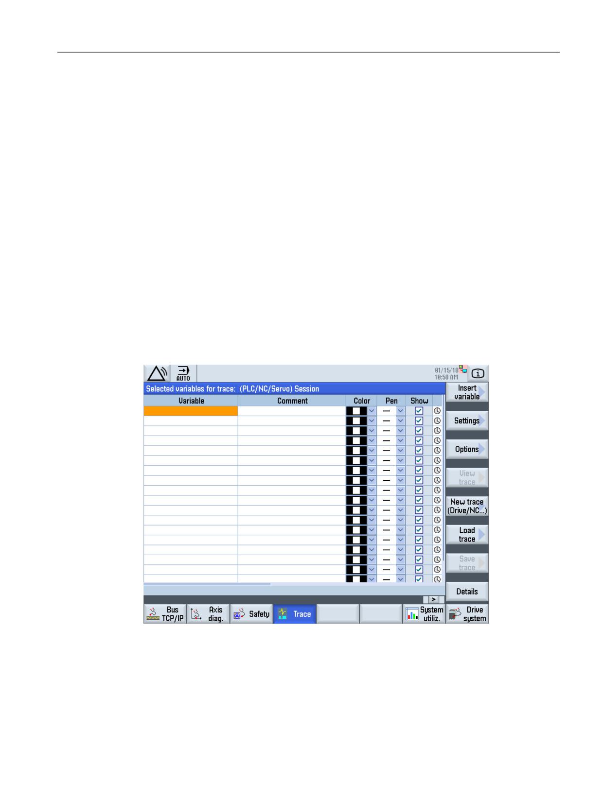
The trace is called in the "Diagnostics" operating area → Menu forward key → "Trace"
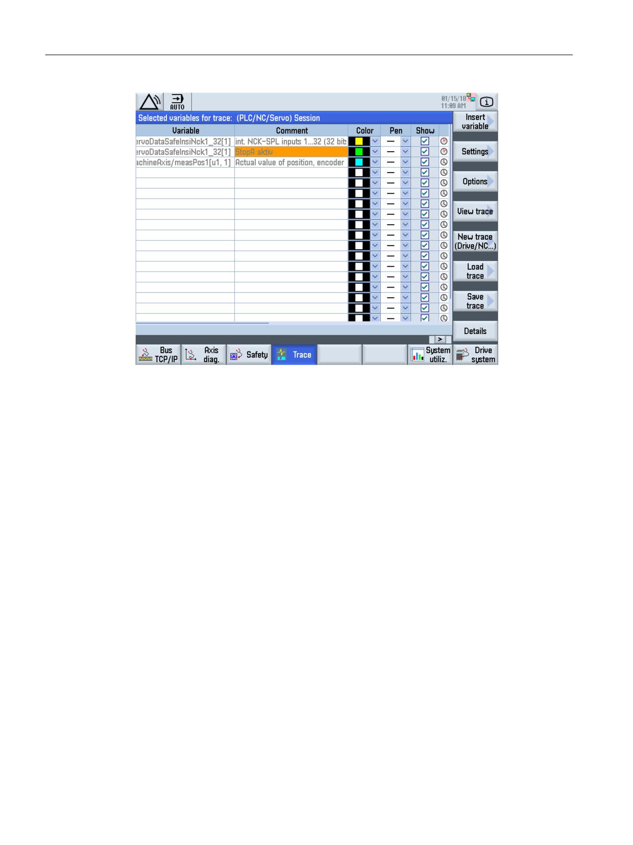
Figure 11-35
Starting the servo trace
The variables can be selected using the "Insert variable" softkey. When inserting a variable, the
associated axis for the measurement is selected, [1] means axis X1. The variable is transferred
into the list and the list completed with "OK".
Safety Integrated (system-integrated)
Function Manual, 10/2020, 6FC5397-4BP40-6BA2
583
Diagnostics
11.1 Troubleshooting procedure
Figure 11-36
Selecting variables for tracing
To start the trace, the system changes into the graphic display and the trace is started using
softkeys "Display trace" and "Start trace".
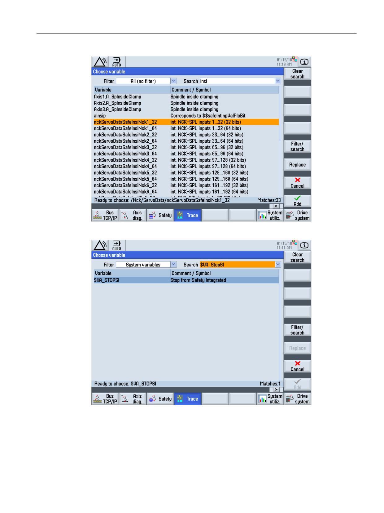
There is also an option to display all variables and then to search for the required variables using
the filter function, in the the following diagram e.g. the internal NCK-SPL inputs using search
word "insi".
You can also specifically search for system variables (see following diagram "Selecting system
variables"), e.g. searching for $VA_STOPSI.
Safety Integrated (system-integrated)
584
Function Manual, 10/2020, 6FC5397-4BP40-6BA2
Diagnostics
11.1 Troubleshooting procedure
Figure 11-37
Selecting variables
Figure 11-38
Selecting system variables
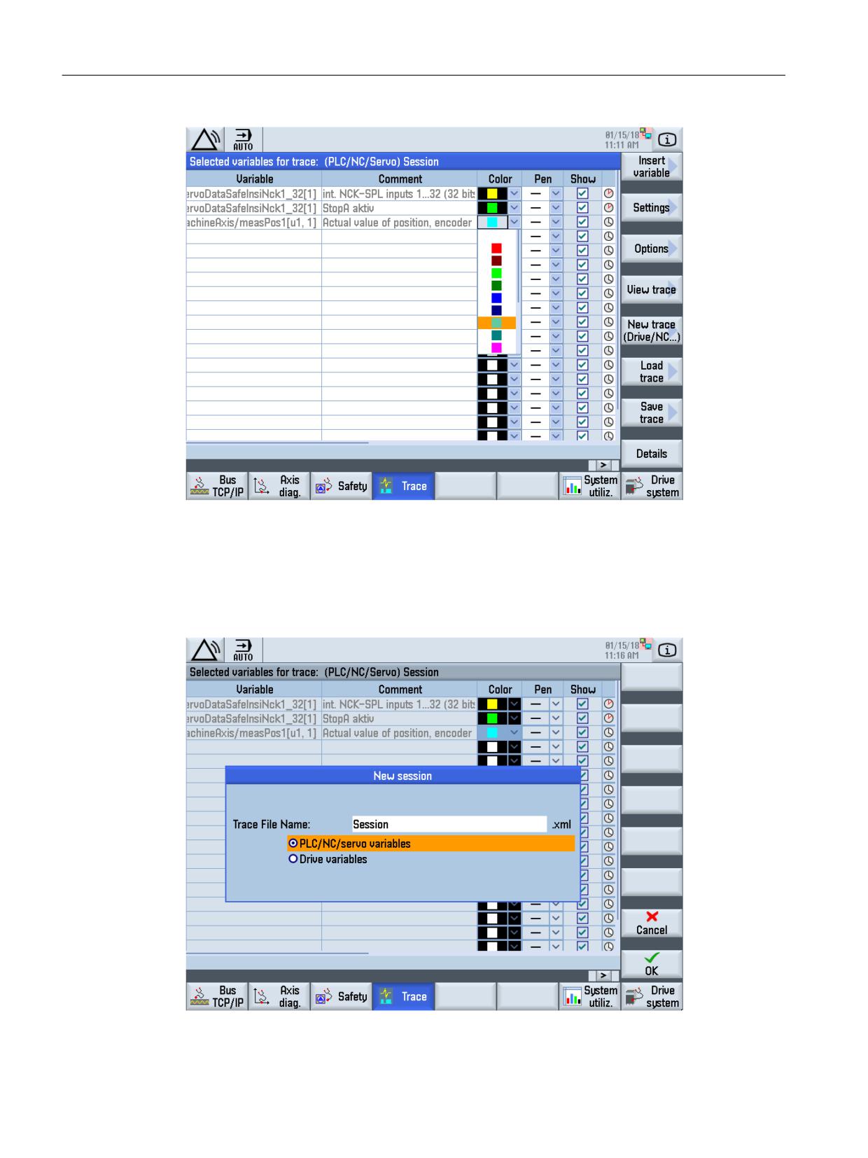
The variables that you wish to trace can also be assigned a particular color.
Safety Integrated (system-integrated)
Function Manual, 10/2020, 6FC5397-4BP40-6BA2
585
Diagnostics
11.1 Troubleshooting procedure
Figure 11-39
Selecting the colors for the trace recording
Example of a trace when SBH is exceeded
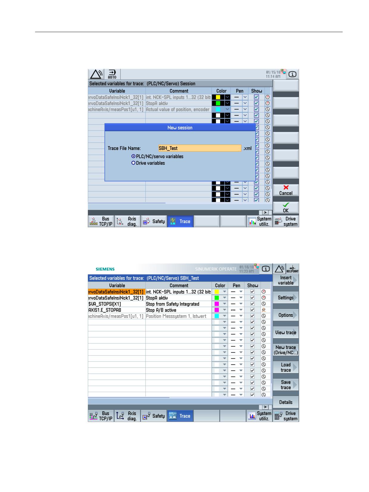
With softkey "New trace (Drive/NC) initially, the session type is called, in this case NC and PLC
variables.
Figure 11-40
General call for a new session
Safety Integrated (system-integrated)
586
Function Manual, 10/2020, 6FC5397-4BP40-6BA2
Diagnostics
11.1 Troubleshooting procedure
The trace is to be performed for Safe Operating Stop, i.e. the trace file name SBH_Test is entered:
Figure 11-41
Trace SBH_test
The variables are determined using the "Insert variable" softkey. The following variables are
selected for SBH_Test:
Figure 11-42
Overview of the variables for SBH test
Safety Integrated (system-integrated)
Function Manual, 10/2020, 6FC5397-4BP40-6BA2
587
Diagnostics
11.1 Troubleshooting procedure
To start the trace, the graphic display is selected using softkeys "Display trace" and "Start trace".
The trace is started.
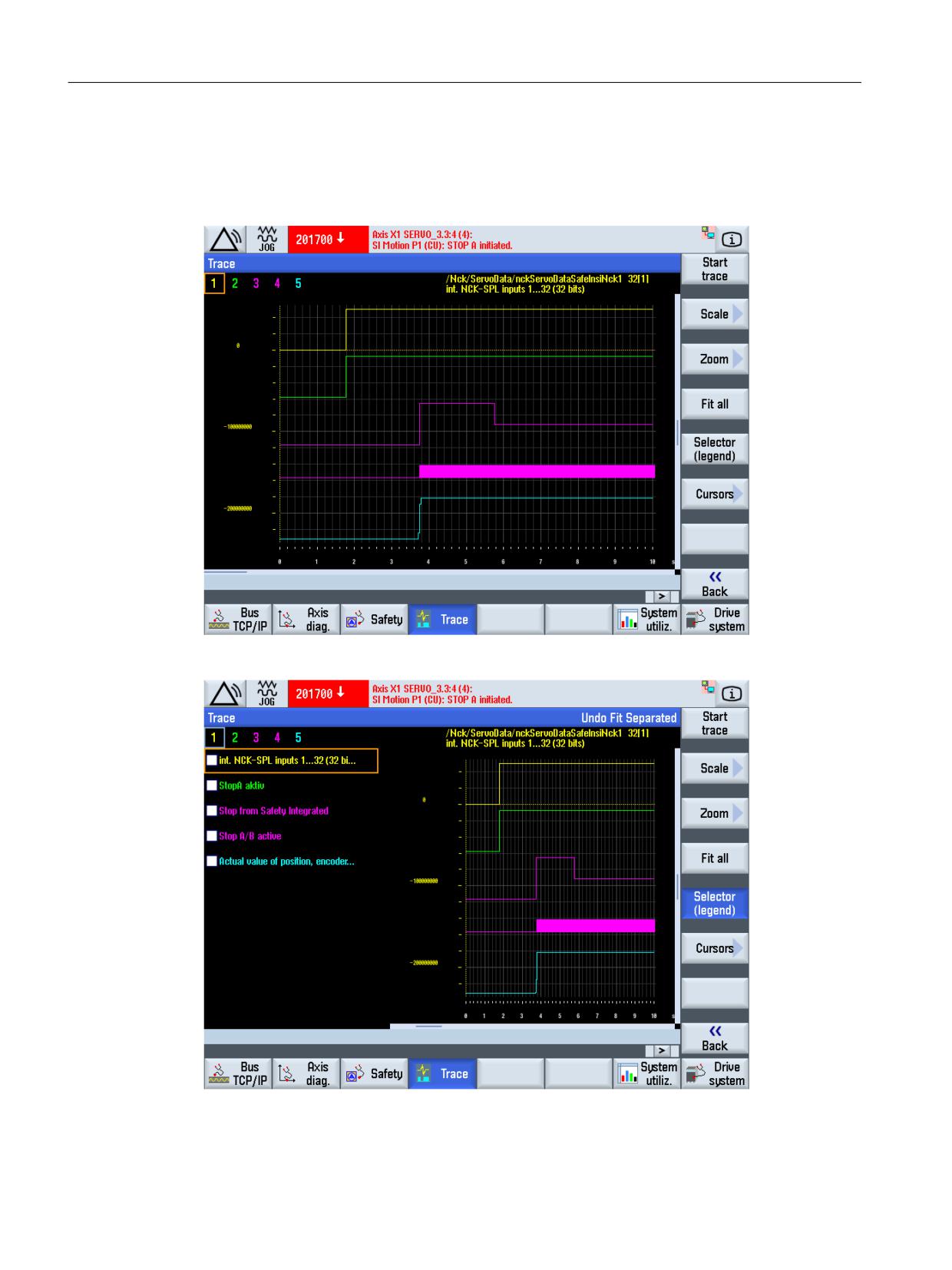
The measuring curves of the variables are shown as example in the following diagrams.
Figure 11-43
Trace SBH exceeded
Figure 11-44
Trace SBH exceeded with legend
Safety Integrated (system-integrated)
588
Function Manual, 10/2020, 6FC5397-4BP40-6BA2
Diagnostics
11.2 NCK safety alarms for SINUMERIK 840D sl
The value range for the trace can be changed using the "Settings" softkey. The "Options" softkey
can be used to change the trace display.
The measurement trace can be saved using the "Save trace" softkey.
11.2
NCK safety alarms for SINUMERIK 840D sl
Alarms for SINUMERIK 840D sl/SINAMICS S120
Detailed explanations of all alarms that are not described here can be found in the following
references for the SINUMERIK 840D sl system with SINAMICS S120:
/DA/, Diagnostics Guide SINUMERIK 840D sl
/LH1/ SINAMICS S120/S150 List Manual
Safety Integrated (system-integrated)
Function Manual, 10/2020, 6FC5397-4BP40-6BA2
589

Diagnostics
11.2 NCK safety alarms for SINUMERIK 840D sl
Alarms for SINUMERIK Safety Integrated
The alarms that can occur in connection with the SI option are listed below:
14710
Channel %1 Block %2 Error in initialization sequence in function %3
Parameter
%1 = channel number
%2 = block number
%3 = identifier
Explanation
After the control has booted, (program)RESET and (program)START, depending on machine data MD20110
$MC_RESET_MODE_MASK and MD20112 $MC_START_MODE_MASK initialization blocks are generated (or not
generated as the case may be).
In this case, errors can occur due to incorrect machine data settings. The errors are output with the same error
messages, which are also issued if the function was incorrectly programmed in the part program.
In order to clearly indicate that an error refers to the initialization sequence, in addition, this alarm is generated.
Parameter %3 specifies which function initiated the alarm:
Control boot and (program) RESET:
Value:
0: Error when synchronizing, preprocessing/main run
1: Error when selecting the tool length compensation
2: Error when selecting the transformation
3: Error when selecting the work offset
When booting, the macro definitions and cycle interfaces are also read-in. If an error occurs here, then this is
signaled with value=4 or value=5.
6: Error when creating 2 1/2-D protection zones when booting (program) START
Value:
100: Error when synchronizing, preprocessing/main run
101: Error when selecting the tool length compensation
102: Error when selecting the transformation
103: Error when selecting the synchronous spindle
104: Error when selecting the work offset
It is especially important to note that when the tool manager is active, it is possible that a locked tool is in the
spindle or in the tool holder that in spite of this should be activated.
For RESET, these tools are activated without having to do anything else.
For START, in addition using MD22562 $MC_TOOL_CHANGE_ERROR_MODE it can be set as to whether an alarm
should be generated or an automatic bypass strategy should be selected.
If the parameter contains 3 values from 200 to 203, then this means that for certain commands (ASUB start,
select overstore, teach in) there are not enough NC blocks for NC block preparation.
Remedy: Increase MD28070 $MC_MM_NUM_BLOCKS_IN_PREP.
Response
Alarm display
Mode group not ready
NC start disable in this channel
Interface signals are set
Safety Integrated (system-integrated)
590
Function Manual, 10/2020, 6FC5397-4BP40-6BA2

Diagnostics
11.2 NCK safety alarms for SINUMERIK 840D sl
14710
Channel %1 Block %2 Error in initialization sequence in function %3
Remedy
Please inform the authorized personnel/service department
For parameter %3=0-3:
If the alarm(s) occur(s) at RESET:
Check the setting of machine data MD20110 $MC_RESET_MODE_MASK, MD20120 $MC_TOOL_RESET_VALUE,
MD20121 $MC_TOOL_PRESEL_RESET_VALUE, MD20122 $MC_TOOL_RESET_NAME (only when tool manage-
ment is active), MD20130 $MC_CUTTING_EDGE_RESET_VALUE, MD20132 $MC_SUMCOR_RESET_VALUE,
MD20126 $MC_TOOL_CARRIER_RESET_VALUE, MD20150 $MC_GCODE_RESET_VALUES, MD20154 $MC_EX-
TERN_GCODE_RESET_VALUES, MD20140 $MC_TRAFO_RESET_VALUE, MD21330 $MC_COUPLE_RE-
SET_MODE_1, MD24002 $MC_CHBFRAME_RESET_MASK.
For parameters %3= 100 -104:
Check the setting of MD20112 $MC_START_MODE_MASK and "..._RESET_..." specified under RESET machine
data. When the tool manager is active, possibly unload the tool - specified in the associated alarm - from
toolholder/spindle - or reset the "locked" state.
For parameters %3= 4 or 5:
Check the macrodefinitions in _N_DEF_DIR. Check cycle directories _N_CST_DIR and _N_CUS_DIR.
For parameter %3= 6:
In addition, Alarm 18002 or 18003 is output. This alarm contains the number of the incorrectly defined pro-
tection zone and an identifier defining what is incorrect in the protection zone definition. The system variables
must then be appropriately corrected.
For parameter %3= 200 to 203:
Increase MD28070 $MC_MM_NUM_BLOCKS_IN_PREP.
Program con-
Clear the alarm with the RESET key. Restart the part program.
tinuation
14751
Channel %1 Block %2 Insufficient resources for motion-synchronized actions (identifier: %3)
Parameter
%1 = channel number
%2 = block number
%3 = identifier
Explanation
To process motion synchronizing actions resources are required. They are configured using machine data
$MC_MM_IPO_BUFFER_SIZE, $MC_MM_NUM_BLOCKS_IN_PREP, $MC_MM_NUM_SAFE_SYNC_ELEMENTS,
$MC_MM_NUM_SYNC_ELEMENTS. If these resources are insufficient for executing the part program, then this
alarm is issued. The parameter %3 shows which resource has run out:
Identifier ≤ 2: increase $MC_MM_IPO_BUFFER_SIZE or $MC_MM_NUM_BLOCKS_IN_PREP.
Identifier > 2: increase $MC_MM_NUM_SYNC_ELEMENTS, $MC_MM_NUM_SAFE_SYNC_ELEMENTS.
Response
Alarm display
Interface signals are set
Remedy
Correct the part program or increase the resources.
Program con-
Clear the alarm with the RESET key. Restart the part program.
tinuation
15189
Channel %1 Block %2 Error executing SAFE.SPF
Parameter
%1 = channel number
%2 = block number, label
Explanation
When processing the NC initialization program for Safety Integrated /_N_CST_DIR/_N_SAFE_SPF an error has
occurred. Alarm 15189 is output together with the alarm that describes the cause of the error. The function is
activated with MD20108 $MC_PROG_EVENT_MASK, bit 5=1.
Safety Integrated (system-integrated)
Function Manual, 10/2020, 6FC5397-4BP40-6BA2
591

Diagnostics
11.2 NCK safety alarms for SINUMERIK 840D sl
15189
Channel %1 Block %2 Error executing SAFE.SPF
Response
NC stop for alarm
Remedy
Carry out an NCK reset (warm restart)
Program con-
Switch control system OFF and ON again.
tinuation
15420
Channel %1 Block %2 Instruction in actual mode not allowed
Parameter
%1 = channel number
%2 = block number, label
Explanation
The alarm is output in the following situations:
• When executing an INI file or definition file (macro or GUD), the interpreter has identified an illegal instruc-
tion (e.g. traversing command).
• In a GUD file, access protection to a machine data with REDEF is to be changed, although an ACCESS file
(_N_SACCESS_DEF, _N_MACCESS_DEF, _NUACCESS_DEF) is available. Access rights for machine data may
then only be changed using one of the ACCESS files with REDEF.
• When executing the safety initialization program /_N_CST_DIR/_N_SAFE_SPF, due to the reduced language
scope that was configured for the purpose, an illegal statement was identified.
Response
Interpreter stop
NC start disable in this channel
Interface signals are set
Alarm display
Remedy
• Correct INI, GUD, or macro file
• Correct part program
Program con-
Clear the alarm with the RESET key. Restart the part program.
tinuation
16964
Channel %1 executing init blocks not fully completed
Parameter
%1 = channel number
Explanation
When booting, init blocks are executed. These ensure that the control is correctly initialized. The alarm is output
if the execution was not able to be correctly ended (generally due to an already existing alarm).
Response
Alarm display
Remedy
Remove the existing alarm.
Program con-
Switch control system OFF and ON again.
tinuation
16965
Channel %1 SAFE.SPF run-up not completed
Parameter
%1 = channel number
Explanation
The alarm is initiated if the safety program /N_CST_DIR/N_SAFE_SPF should be executed when booting and was
not completed after four times the time, which is defined in MD $MN_SPL_START_TIMEOUT. One reason could
be an extremely long execution time of SAFE.SPF. The channel number specifies which channel is the cause of
the error.
Safety Integrated (system-integrated)
592
Function Manual, 10/2020, 6FC5397-4BP40-6BA2

Diagnostics
11.2 NCK safety alarms for SINUMERIK 840D sl
16965
Channel %1 SAFE.SPF run-up not completed
Response
Alarm display
NC not ready
NC start disable in this channel
Mode group not ready
Interface signals are set
NC stop for alarm
Remedy
Increase MD $MN_SAFE_SPL_START_TIMEOUT
Program con-
Clear the alarm with the RESET key. Restart the part program.
tinuation
20095
Axis %1 illegal holding torque, measured torque %2
Parameter
%1 = axis name, spindle number
%2 = measured holding torque when selecting the brake test
Explanation
The actually measured holding torque cannot be provided with the existing parameterization of the brake test.
Response
Alarm display
The function test of the mechanical brake system is aborted
The PLC block FB11 for the sequence control to test the mechanical brake system is exited with a fault (fault
detection = 2). This means that the request - "start brake test" - is not even effective for the axis.
Remedy
Check the actual parameterization of the function test of the mechanical braking system:
• The torque due to weight in drive parameter p1532 should be as far as possible equal to the currently
measured holding torque. The measured holding torque is displayed in this alarm.
• The holding torque for the brake test in MD $MA_SAFE_BRAKETEST_TORQUE must be parameterized higher
than the currently set holding torque.
Program con-
Clear the alarm with the Clear key or with NC-START.
tinuation
20096
Axis %1 brake test aborted, additional info %2
Parameter
%1 = axis name, spindle number
%2 = fault information, based on $VA_FXS_INFO
Explanation
The brake test has detected a problem. The additional information provides details of the cause of the alarm.
An explanation is provided in the documentation about the system variables $VA_FXS_INFO
Supplementary info:
0: No additional information available
1: Axis type is neither a PLC nor a command axis
2: Limit position reached, motion stopped
3: Interrupted by an axis RESET (DB31-61, DBB28 bit1)
4: Monitoring window exited
5: Torque reduction rejected by drive
6: PLC has withdrawn the enable signal
Response
Alarm display
Interface signals are set
Safety Integrated (system-integrated)
Function Manual, 10/2020, 6FC5397-4BP40-6BA2
593

Diagnostics
11.2 NCK safety alarms for SINUMERIK 840D sl
20096
Axis %1 brake test aborted, additional info %2
Remedy
Note the supplementary conditions of the brake test, refer to supplementary information
Program con-
Clear the alarm with the Clear key or with NC-START.
tinuation
20097
Axis %1 incorrect direction, brake test
Parameter
%1 = axis name, spindle number
Explanation
As a result of the selected traversing direction, the brake test is carried out for the existing load torque with an
incorrect torque.
Response
Alarm display
Remedy
• Carry out the brake test in the other traversing direction
• Adapt drive parameter p1532 more precisely to the actual situation. The alarm only occurs if the actual
torque deviates by more than 7.5% from SINAMICS parameter p1532
• Using MD $MA_SAFE_BRAKETEST_CONTROL, bit 0 = 1, activate the automatic load torque determination at
the beginning of the brake test.
Program con-
Clear the alarm with the Clear key or with NC-START.
tinuation
20149
Channel %1 Block %2 motion-synchronized action: Index invalid
Parameter
%1 = channel number
%2 = block number
Explanation
An invalid index was used when accessing a variable in the motion-synchronous action.
Example: ...DO $R[$AC_MARKER[1]] = 100
The error occurs if marker 1 has a higher value than the maximum permissible R-parameter number.
Response
NC start disable in this channel
Interface signals are set
Alarm display
NC stop for alarm
Remedy
Use a valid index.
Program con-
Clear the alarm with the RESET key. Restart the part program.
tinuation
22001
Channel %1 Block %2 Axis %3: Braking ramp longer than STOP D time. Reason: %4
Parameter
%1 channel number
%2 Block number
%3 Axis name
%4 identification of cause
Explanation
The actual axis dynamic performance is not sufficient to come to a standstill in time when a STOP D is initiated.
The reasons specified in parameter 4 are:
1: $MA_MAX_AX_ACCEL too low
2. $MA_MAX_AX_JERK too low
3. Excessively high acceleration reduction programmed with ACC
4. Excessively high jerk reduction programmed with JERKLIM
Safety Integrated (system-integrated)
594
Function Manual, 10/2020, 6FC5397-4BP40-6BA2

Diagnostics
11.2 NCK safety alarms for SINUMERIK 840D sl
22001
Channel %1 Block %2 Axis %3: Braking ramp longer than STOP D time. Reason: %4
Response
Alarm display
Remedy
Increase SAFE_STOP_SWITCH_TIME_D. Increase $MA_MAX_AX_ACCEL and $MA_MAX_AX_JERK. . Increase
programmed acceleration (ACC) or jerk (JERKIM)
Alarm can be suppressed using MD11415 $MN_SUPPRESS_ALARM_MASK_2 Bit 13
Program con-
Clear the alarm with the Clear key or with NC-START.
tinuation
22002
Channel %1 Spindle %2: Braking ramp longer than STOP D time. Gearbox stage %3. Reason: %4
Parameter
%1 channel number
%2 Spindle
%3 Gear stage
%4 identification of cause
Explanation
The configured dynamic values of the spindle are not sufficient to come to a standstill in time when a STOP D
is initiated. Parameter 3 contains the gear stage, whose braking time - from the configured dynamic values -
exceeds the STOP D time the most. Parameter 4 includes an ID for the MD involved:
10: Dynamic response for closed-loop speed control: MD35130 $MA_GEAR_STEP_MAX_VELO_LIMIT,
MD35200 $MA_GEAR_STEP_SPEEDCTRL_ACCEL
11: Dynamic response for closed-loop position control: MD35135 $MA_GEAR_STEP_PC_MAX_VELO_LIMIT,
MD35210 GEAR_STEP_POSCTRL_ACCEL
21: Dynamic response for tapping using G331, G332: MD35135 $MA_GEAR_STEP_PC_MAX_VELO_LIMIT,
MD35212 GEAR_STEP_POSCTRL_ACCEL2
Response
Alarm display
Remedy
Increase MD36953 $MA_SAFE_STOP_SWITCH_TIME_D or reduce the braking time by changing the configured
dynamic response of the spindle. The alarm can be suppressed using MD11415 $MN_SUP-
PRESS_ALARM_MASK_2 bit 13
Program con-
Clear the alarm with the Clear key or with NC-START.
tinuation
27000
Axis %1 is not safely referenced
Parameter
%1 = axis name, spindle number
Explanation
There are two reasons for this alarm:
• the user has still not acknowledged the machine position,
• the machine position has not yet been verified through follow-up referencing.
Even if the axis is already referenced there is no acknowledgement that referencing has supplied the correct
result. For example, incorrect results can occur if the axis was moved after the control was powered-down - with
the result that the stop position saved prior to powering-down is no longer correct. To ensure that this does not
happen, the user must acknowledge the displayed actual position after the first referencing operation.
After the user agreement has been set for the first time, the axis must be subsequently referenced each time
that the control is booted (with absolute encoders, this subsequent referencing is automatically executed). This
procedure is carried out to verify the stop position saved prior to powering-down the control.
The alarm display can be set using MD10094 $MN_SAFE_ALARM_SUPPRESS_LEVEL (MD≥3) so that the group
alarm 27100 is displayed for all SI axes.
Response
Alarm display
The SGA "axis safely referenced" is not set. SE is disabled if the safe actual position has not yet been acknowl-
edged by the user agreement. If the user agreement is set, SE remains active. The Safe Cams are calculated and
output, but their significance is limited because referencing has not been acknowledged.
Safety Integrated (system-integrated)
Function Manual, 10/2020, 6FC5397-4BP40-6BA2
595

Diagnostics
11.2 NCK safety alarms for SINUMERIK 840D sl
27000
Axis %1 is not safely referenced
Remedy
Move the axis to a known position, change to the "referencing" mode and press the softkey "Agreement". Check
the positions displayed in the agreement screen at the machine. If these correspond to those expected at the
known position, confirm this using the toggle key. If the user agreement has already been set, re-reference the
axis.
The user agreement can only be changed in key-actuated switch setting 3 or after entering a password.
Warning:
If the axis has not been safely referenced and the user has not issued a user agreement, then the following
applies:
- the Safe Cams are still not safe.
- the safe limit positions are still not active
Program con-
The alarm is no longer displayed when the alarm cause has been removed. No other operator actions are
tinuation
required
27001
Axis %1 error in a monitoring channel, Code%2, values: NCK%3, drive %4
Parameter
%1 = axis name, spindle number
%2 = supplementary information, crosswise data comparison index
%3 = supplementary information, comparison value, NCK
%4 = supplementary information, comparison value, drive
Explanation
The status of the safety-related monitoring functions are cyclically and mutually compared between the two
monitoring channels (NCK and drive). The comparison is carried out separately for each NCK/drive combination.
A criterion in a comparison list is compared between the NCK and drive in each monitoring clock cycle
(MD10091 $MN_INFO_SAFETY_CYCLE_TIME); the next criterion is compared in the next monitoring clock cycle
etc. Once the complete comparison list has been processed, the comparisons are processed again from the
beginning. The resulting total comparison time to process the list is displayed in MD10092 $MN_INFO_CROSS-
CHECK_CYCLE_TIME (factor x MD10091 $MN_INFO_SAFETY_CYCLE_TIME - the factor can differ depending on
the particular software version).
The "Defect in a monitoring channel" alarm is only output if the mutual comparison of the two monitoring
channels detects a difference between the input data or results of the monitoring. One of the monitoring
functions is no longer operating reliably.
The crosswise comparison index, output under %2, is also known as STOP F code. The STOP F code is also output
in Alarm 27001 where the NCK detected a crosswise comparison error for the first time. The STOP F code of the
drive (belonging to Alarm C01711) can be taken from the diagnostics screen or the drive parameter r9795. If a
difference is detected at several comparison steps, then also several STOP F code values can be displayed,
alternating, at these positions.
There are error profiles that are identified as a result of several comparison operations of the comparison list.
This means that the displayed STOP F code value doesn't always provide a clear statement regarding the cause
of the error. The associated procedure is then explained for each of the individual error codes.
0
No error has been detected in this monitoring channel. Alarm 27001 means that it involved one of the subse-
quent alarms (follow-on alarms) of alarm C01711 - and the valid STOP F code value is to be determined using
the diagnostics display or the drive parameter r9795.
1
For the monitoring functions SBH, SG, SBR or SE, a different state has occurred between the NCK and drive. The
actual status image (result list 1) is output from the NCK as supplementary input %3 (comparison value, NCK)
and the actual status image from the drive is output as supplementary info %4 (comparison value, drive). The
two supplementary infos are also saved in drive parameters r9710[0] (NCK) and r9710[1] (drive).
An example for evaluating the bit-coded result list is provided in the description of the drive machine data.
Remedy
Safety Integrated (system-integrated)
596
Function Manual, 10/2020, 6FC5397-4BP40-6BA2

Diagnostics
11.2 NCK safety alarms for SINUMERIK 840D sl
27001
Axis %1 error in a monitoring channel, Code%2, values: NCK%3, drive %4
The difference in the states between the drive and NCK should be determined and the function involved should
be investigated in more detail.
Example
State, NCK: SBH is active and ok
State, drive: SG1 is active and ok
The fault is caused due to the fact that the SGE "SBH deselection" is controlled differently. The signal source
should be checked on both the NCK and drive sides. Generally, the different control (in operation) is a result of
a hardware failure associated with the sensor signal involved. In the commissioning phase, the cause can also
be parameterizing or programming errors.
2
For the monitoring function SN or n < nx, a different state has occurred between the NCK and drive.
The actual status image of the NCK (result list 2) is output as supplementary info %3 (comparison value NCK)
and the actual status image from the drive is output as supplementary info %4 (comparison value, drive). The
two result lists are also written to as parameter r9711[0] (NCK) and r9711[1] (drive). An example for evaluating
the bit-coded result list is provided in the description of the drive parameter.
Remedy
The difference in the states between the drive and NCK should be determined and the function involved should
be investigated in more detail.
3
The difference between the safe actual value NCK and drive is greater than that set in MD36942
$MA_SAFE_POS_TOL.
When using the actual value synchronization, the difference of the speed (determined based on the safety
actual values) is greater than that set in MD36949 $MA_SAFE_SLIP_VELO_TOL.
Remedy
Commissioning phase:
The encoder evaluation for the NCK and drive is not correctly set
→ correct the encoder evaluation.
In operation:
The actual values differ due to mechanical faults (transmission belts, traversing to mechanical limit, wear and
tolerance windows that have been set too narrow, encoder faults...)
- check the mechanical configuration and the encoder signals
4 not assigned
5
The setting in MD36901 $MA_SAFE_FUNCTION_ENABLE does not correspond with the associated drive pa-
rameter assignment.
Remedy
Copy SI data
6
The setting in MD36931 $MA_SAFE_VELO_LIMIT[0] does not correspond with the associated drive parameter
assignment.
Remedy
Copy SI data
7
The setting in MD36931 $MA_SAFE_VELO_LIMIT[1] does not correspond with the associated drive parameter
assignment.
Remedy
Safety Integrated (system-integrated)
Function Manual, 10/2020, 6FC5397-4BP40-6BA2
597

Diagnostics
11.2 NCK safety alarms for SINUMERIK 840D sl
27001
Axis %1 error in a monitoring channel, Code%2, values: NCK%3, drive %4
Copy SI data
8
The setting in MD36931 $MA_SAFE_VELO_LIMIT[2] does not correspond with the associated drive parameter
assignment.
Remedy
Copy SI data
9
The setting in MD36931 $MA_SAFE_VELO_LIMIT[3] does not correspond with the associated drive parameter
assignment.
Remedy
Copy SI data
10
The setting in MD36930 $MA_SAFE_STANDSTILL_TOL does not correspond with the associated drive parameter
assignment.
Remedy
Copy SI data
11
The setting in MD36934 $MA_SAFE_POS_LIMIT_PLUS[0] does not correspond with the associated drive pa-
rameter assignment.
Remedy
Copy SI data
12
The setting in MD36935 $MA_SAFE_POS_LIMIT_MINUS[0] does not correspond with the associated drive pa-
rameter assignment.
Remedy
Copy SI data
13
The setting in MD36934 $MA_SAFE_POS_LIMIT_PLUS[1] does not correspond with the associated drive pa-
rameter assignment.
Remedy
Copy SI data
14
The setting in MD36935 $MA_SAFE_POS_LIMIT_MINUS[1] does not correspond with the associated drive pa-
rameter assignment.
Remedy
Copy SI data
15
The setting in MD36936 $MA_SAFE_CAM_POS_PLUS[0] + MD36940 $MA_SAFE_CAM_TOL does not corre-
spond with the associated drive parameter assignment.
Remedy
Copy SI data
16
The setting in MD36936 $MA_SAFE_CAM_POS_PLUS[0] does not correspond with the associated drive param-
eter assignment.
Remedy
Safety Integrated (system-integrated)
598
Function Manual, 10/2020, 6FC5397-4BP40-6BA2

Diagnostics
11.2 NCK safety alarms for SINUMERIK 840D sl
27001
Axis %1 error in a monitoring channel, Code%2, values: NCK%3, drive %4
Copy SI data
17
The setting in MD36937 $MA_SAFE_CAM_POS_MINUS[0] + MD36940 $MA_SAFE_CAM_TOL does not corre-
spond with the associated drive parameter assignment.
Remedy
Copy SI data
18
The setting in MD36937 $MA_SAFE_CAM_POS_MINUS[0] does not correspond with the associated drive pa-
rameter assignment.
Remedy
Copy SI data
19
The setting in MD36936 $MA_SAFE_CAM_POS_PLUS[1] + MD36940 $MA_SAFE_CAM_TOL does not corre-
spond with the associated drive parameter assignment.
Remedy
Copy SI data
20
The setting in MD36936 $MA_SAFE_CAM_POS_PLUS[1] does not correspond with the associated drive param-
eter assignment.
Remedy
Copy SI data
21
The setting in MD36937 $MA_SAFE_CAM_POS_MINUS[1] + $MA_SAFE_CAM_TOL does not correspond with
the associated drive parameter assignment.
Remedy
Copy SI data
22
The setting in MD36937 $MA_SAFE_CAM_POS_MINUS[1] does not correspond with the associated drive pa-
rameter assignment.
Remedy
Copy SI data
23
The setting in MD36936 $MA_SAFE_CAM_POS_PLUS[2] + MD36940 $MA_SAFE_CAM_TOL does not corre-
spond with the associated drive parameter assignment.
Remedy
Copy SI data
24
The setting in MD36936 $MA_SAFE_CAM_POS_PLUS[2] does not correspond with the associated drive param-
eter assignment.
Remedy
Copy SI data
25
The setting in MD36937 $MA_SAFE_CAM_POS_MINUS[2] + MD36940 $MA_SAFE_CAM_TOL does not corre-
spond with the associated drive parameter assignment.
Remedy
Safety Integrated (system-integrated)
Function Manual, 10/2020, 6FC5397-4BP40-6BA2
599

Diagnostics
11.2 NCK safety alarms for SINUMERIK 840D sl
27001
Axis %1 error in a monitoring channel, Code%2, values: NCK%3, drive %4
Copy SI data
26
The setting in MD36937 $MA_SAFE_CAM_POS_MINUS[2] does not correspond with the associated drive pa-
rameter assignment.
Remedy
Copy SI data
27
The setting in MD36936 $MA_SAFE_CAM_POS_MINUS[3] + MD36940 $MA_SAFE_CAM_TOL does not corre-
spond with the associated drive parameter assignment.
Remedy
Copy SI data
28
The setting in MD36936 $MA_SAFE_CAM_POS_PLUS[3] does not correspond with the associated drive param-
eter assignment.
Remedy
Copy SI data
29
The setting in MD36937 $MA_SAFE_CAM_POS_MINUS[3] + MD36940 $MA_SAFE_CAM_TOL does not corre-
spond with the associated drive parameter assignment.
Remedy
Copy SI data
30
The setting in MD36937 $MA_SAFE_CAM_POS_MINUS[3] does not correspond with the associated drive pa-
rameter assignment.
Remedy
Copy SI data
31
The settings in MD36942 $MA_SAFE_POS_TOL. or MD36949 $MA_SAFE_SLIP_VELO_TOL do not correspond
with the associated drive parameter assignment.
Remedy
Copy SI data
32
The setting in MD36944 $MA_SAFE_REFP_POS_TOL does not correspond with the associated drive parameter
assignment.
Remedy
Copy SI data
33
The setting in MD36951 $MA_SAFE_VELO_SWITCH_DELAY does not correspond with the associated drive
parameter assignment.
Remedy
Copy SI data
34
The setting in MD36950 $MA_SAFE_MODE_SWITCH_TIME does not correspond with the associated drive pa-
rameter assignment.
Remedy
Safety Integrated (system-integrated)
600
Function Manual, 10/2020, 6FC5397-4BP40-6BA2

Diagnostics
11.2 NCK safety alarms for SINUMERIK 840D sl
27001
Axis %1 error in a monitoring channel, Code%2, values: NCK%3, drive %4
Copy SI data
35
The setting in MD36956 $MA_SAFE_PULSE_DISABLE_DELAY does not correspond with the associated drive
parameter assignment.
Remedy
Copy SI data
36
The setting in MD36957 $MA_SAFE_PULSE_DIS_CHECK_TIME does not correspond with the associated drive
parameter assignment.
Remedy
Copy SI data
37
The setting in MD36952 $MA_SAFE_STOP_SWITCH_TIME_C does not correspond with the associated drive
parameter assignment.
Remedy
Copy SI data
38
The setting in MD36953 $MA_SAFE_STOP_SWITCH_TIME_D does not correspond with the associated drive
parameter assignment.
Remedy
Copy SI data
39
The setting in MD36954 $MA_SAFE_STOP_SWITCH_TIME_E does not correspond with the associated drive
parameter assignment.
Remedy
Copy SI data
40
The setting in MD36961 $MA_SAFE_VELO_STOP_MODE does not correspond with the associated drive param-
eter assignment.
Remedy
Copy SI data
41
The setting in MD36962 $MA_SAFE_POS_STOP_MODE does not correspond with the associated drive param-
eter assignment.
Remedy
Copy SI data
42
The setting in MD36960 $MA_SAFE_STANDSTILL_VELO_TOL does not correspond with the associated drive
parameter assignment.
Remedy
Copy SI data
43
Stop response, memory test.
44 - 57
Safety Integrated (system-integrated)
Function Manual, 10/2020, 6FC5397-4BP40-6BA2
601

Diagnostics
11.2 NCK safety alarms for SINUMERIK 840D sl
27001
Axis %1 error in a monitoring channel, Code%2, values: NCK%3, drive %4
Explanation
Error codes 44-57 cannot be clearly assigned to an error cause. For the monitoring functions that run internally
(e.g. SG), monitoring limits are internally generated that are referred to a monitoring clock cycle.
Example: SG1 = 2000 mm/min, monitoring clock cycle = 12 ms
If SG1 is active, then a check is made in every monitoring clock cycle (MCC) as to whether SG1 was exceeded.
This means that in MCC[n], based on the actual value, a positive and negative actual value limit is defined that
may not be exceeded in MCC[n+1] in order to still comply with SG1.
SG1 = 2000 mm/min = 33.33 mm/s = 0.4 mm/MCC (for each 12 ms)
If the axis moves more than 0.4 mm in a monitoring clock cycle, then SG1 would be violated.
The limit values, specified above, in MCC[n+1] are then
Positive: Position actual value (MCC[n]) + 0.4 mm
negative: position actual value (MCC[n]) -0.4 mm
The resulting monitoring limits (positive and negative) that are, in turn determined independently for both
monitoring channels (NCK and drive) are also compared just like the safe actual positions (refer to fault code 3).
The comparison is to check for a difference < MD36942 $MA_SAFE_POS_TOL.
If the difference is greater than MD36942 $MA_SAFE_POS_TOL, then the appropriate fault code is output.
The limit values are then re-generated and compared in every monitoring cycle independently of whether the
associated monitoring function is active or not.
This means that there are three possible causes for this fault code group.
Causes and remedy
Possible cause 1 (only when commissioning or changing the MD)
The tolerance value for the monitoring function is set differently for the NCK and drive. This situation actually
only occurs when commissioning the system or making changes and is generally already covered by the
previous fault codes.
Remedy:
Set the relevant machine data the same.
Possible cause 2 (in operation)
The limit values are determined based on the actual value. This means that when the safe actual values of the
NCK and drive differ then the limit values are also different by the defined clearance → i.e. the fault code
corresponds to the fault image of fault code 3. This is determined by checking the safe actual positions.
Remedy (refer to fault code 3)
Possible cause 3 (in operation)
The associated monitoring function is already active in a monitoring channel - while in the other monitoring
channel another monitoring function is still active.
This is the case if the safe actual positions of the NCK and drive do not differ but instead there is an entry in drive
parameters r9710/r9711 (and the 1 appears in parameter r9725) → i.e. the fault code corresponds to the fault
profile of fault code 1. This can also be identified using the fault message if for %3 = supplementary info
comparison value NCK or %4 = supplementary info comparison value drive no real limit value is output but only
the value of the calculated tolerance (refer to the example above (SG1 = 2000 mm/min = 0.4 mm/monitoring
clock cycle), a value of 400 would be displayed as 4%).
Remedy: refer to fault code 1.
44
Upper limit value for SG1 = position actual value + MD36931 $MA_SAFE_VELO_LIMIT[0] referred to a moni-
toring clock cycle
Remedy
Refer to Section 44-57 (hidden fault code 3 or 1)
45
Safety Integrated (system-integrated)
602
Function Manual, 10/2020, 6FC5397-4BP40-6BA2

Diagnostics
11.2 NCK safety alarms for SINUMERIK 840D sl
27001
Axis %1 error in a monitoring channel, Code%2, values: NCK%3, drive %4
Lower limit value for SG1 = position actual value - MD36931 $MA_SAFE_VELO_LIMIT[0] referred to a monitor-
ing clock cycle
Remedy
Refer to Section 44-57 (hidden fault code 3 or 1)
46
Upper limit value for SG2 = position actual value + MD36931 $MA_SAFE_VELO_LIMIT[1] referred to a moni-
toring clock cycle
Remedy
Refer to Section 44-57 (hidden fault code 3 or 1)
47
Lower limit value for SG2 = position actual value - MD36931 $MA_SAFE_VELO_LIMIT[1] referred to a monitor-
ing clock cycle
Remedy
Refer to Section 44-57 (hidden fault code 3 or 1)
48
Upper limit value for SG3 = position actual value + MD36931 $MA_SAFE_VELO_LIMIT[2] referred to a moni-
toring clock cycle
Remedy
Refer to Section 44-57 (hidden fault code 3 or 1)
49
Lower limit value for SG3 = position actual value - MD36931 $MA_SAFE_VELO_LIMIT[2] referred to a monitor-
ing clock cycle
Remedy
Refer to Section 44-57 (hidden fault code 3 or 1)
50
Upper limit value for SG4 = position actual value + MD36931 $MA_SAFE_VELO_LIMIT[3] referred to a moni-
toring clock cycle
Remedy
Refer to Section 44-57 (hidden fault code 3 or 1)
51
Lower limit value for SG4 = position actual value - MD36931 $MA_SAFE_VELO_LIMIT[3] referred to a monitor-
ing clock cycle
Remedy
Refer to Section 44-57 (hidden fault code 3 or 1)
52
Upper limit value for SBH
Position actual value (when SBH is activated) + MD36930 $MA_SAFE_STANDSTILL_TOL.
Remedy
Refer to Section 44-57 (hidden fault code 3 or 1)
53
Lower limit value for SBH
Position actual value (when SBH is activated) - MD36930 $MA_SAFE_STANDSTILL_TOL.
Remedy
Refer to Section 44-57 (hidden fault code 3 or 1)
Safety Integrated (system-integrated)
Function Manual, 10/2020, 6FC5397-4BP40-6BA2
603

Diagnostics
11.2 NCK safety alarms for SINUMERIK 840D sl
27001
Axis %1 error in a monitoring channel, Code%2, values: NCK%3, drive %4
54
Upper limit value for n < nx (plus tolerance)
Position actual value + MD36946 $MA_SAFE_VELO_X (referred to a monitoring clock cycle) + MD36942
$MA_SAFE_POS_TOL.
Remedy
Refer to Section 44-57 (hidden fault code 3 or 1)
55
Upper limit value for n < nx
Position actual value + MD36946 $MA_SAFE_VELO_X (referred to a monitoring clock cycle)
Remedy
Refer to Section 44-57 (hidden fault code 3 or 1)
56
Lower limit value for n<nx
Position actual value - MD36946 $MA_SAFE_VELO_X (referred to a monitoring clock cycle)
Remedy
Refer to Section 44-57 (hidden fault code 3 or 1)
57
Upper limit value for n<nx (plus tolerance)
Position actual value + MD36946 $MA_SAFE_VELO_X (referred to a monitoring clock cycle) - MD36942
$MA_SAFE_POS_TOL.
Remedy
Refer to Section 44-57 (hidden fault code 3 or 1)
58
There is a difference in the active request for an external STOP. Two factors determine the resulting external
STOP request for a monitoring channel.
• The STOP requested via the SGE interface
• The STOP passed-through from the other monitoring channel
The STOP of the active request is specified as fine error code for the NCK and drive. The following values are
possible:
0 = no Stop
2 = Stop E
3 = Stop D
4 = Stop C
7 = STOP A
59
The setting in MD36932 $MA_SAFE_VELO_OVR_FACTOR[0] does not correspond with the associated drive
parameter assignment.
Remedy
Copy SI data
60
The setting in MD36932 $MA_SAFE_VELO_OVR_FACTOR[1] does not correspond with the associated drive
parameter assignment.
Remedy
Copy SI data
Safety Integrated (system-integrated)
604
Function Manual, 10/2020, 6FC5397-4BP40-6BA2

Diagnostics
11.2 NCK safety alarms for SINUMERIK 840D sl
27001
Axis %1 error in a monitoring channel, Code%2, values: NCK%3, drive %4
61
The setting in MD36932 $MA_SAFE_VELO_OVR_FACTOR[2] does not correspond with the associated drive
parameter assignment.
Remedy
Copy SI data
62
The setting in MD36932 $MA_SAFE_VELO_OVR_FACTOR[3] does not correspond with the associated drive
parameter assignment.
Remedy
Copy SI data
63
The setting in MD36932 $MA_SAFE_VELO_OVR_FACTOR[4] does not correspond with the associated drive
parameter assignment.
Remedy
Copy SI data
64
The setting in MD36932 $MA_SAFE_VELO_OVR_FACTOR[5] does not correspond with the associated drive
parameter assignment.
Remedy
Copy SI data
65
The setting in MD36932 $MA_SAFE_VELO_OVR_FACTOR[6] does not correspond with the associated drive
parameter assignment.
Remedy
Copy SI data
66
The setting in MD36932 $MA_SAFE_VELO_OVR_FACTOR[7] does not correspond with the associated drive
parameter assignment.
Remedy
Copy SI data
67
The setting in MD36932 $MA_SAFE_VELO_OVR_FACTOR[8] does not correspond with the associated drive
parameter assignment.
Remedy
Copy SI data
68
The setting in MD36932 $MA_SAFE_VELO_OVR_FACTOR[9] does not correspond with the associated drive
parameter assignment.
Remedy
Copy SI data
69
The setting in MD36932 $MA_SAFE_VELO_OVR_FACTOR[10] does not correspond with the associated drive
parameter assignment.
Remedy
Copy SI data
Safety Integrated (system-integrated)
Function Manual, 10/2020, 6FC5397-4BP40-6BA2
605

Diagnostics
11.2 NCK safety alarms for SINUMERIK 840D sl
27001
Axis %1 error in a monitoring channel, Code%2, values: NCK%3, drive %4
70
The setting in MD36932 $MA_SAFE_VELO_OVR_FACTOR[11] does not correspond with the associated drive
parameter assignment.
Remedy
Copy SI data
71
The setting in MD36932 $MA_SAFE_VELO_OVR_FACTOR[12] does not correspond with the associated drive
parameter assignment.
Remedy
Copy SI data
72
The setting in MD36932 $MA_SAFE_VELO_OVR_FACTOR[13] does not correspond with the associated drive
parameter assignment.
Remedy
Copy SI data
73
The setting in MD36932 $MA_SAFE_VELO_OVR_FACTOR[14] does not correspond with the associated drive
parameter assignment.
Remedy
Copy SI data
74
The setting in MD36932 $MA_SAFE_VELO_OVR_FACTOR[15] does not correspond with the associated drive
parameter assignment.
Remedy
Copy SI data
75
The setting in MD36946 $MA_SAFE_VELO_X or MD36947 $MA_SAFE_VELO_X_HYSTERESIS does not corre-
spond with the associated drive parameter assignment.
Remedy
Copy SI data
76
The setting in MD36963 $MA_SAFE_VELO_STOP_REACTION[0] does not correspond with the associated drive
parameter assignment.
Remedy
Copy SI data
77
The setting in MD36963 $MA_SAFE_VELO_STOP_REACTION[1] does not correspond with the associated drive
parameter assignment.
Remedy
Copy SI data
78
The setting in MD36963 $MA_SAFE_VELO_STOP_REACTION[2] does not correspond with the associated drive
parameter assignment.
Remedy
Copy SI data
Safety Integrated (system-integrated)
606
Function Manual, 10/2020, 6FC5397-4BP40-6BA2

Diagnostics
11.2 NCK safety alarms for SINUMERIK 840D sl
27001
Axis %1 error in a monitoring channel, Code%2, values: NCK%3, drive %4
79
The setting in MD36963 $MA_SAFE_VELO_STOP_REACTION[3] does not correspond with the associated drive
parameter assignment.
Remedy
Copy SI data
80
Modulo value, Safe Cam $MA_SAFE_MODULO_RANGE
Remedy
Copy SI data
81
The setting in MD36948 $MA_SAFE_STOP_VELO_TOL does not correspond with the associated drive parameter
assignment.
Remedy
Copy SI data
82
When controlling the SG correction factor-SGEs[0..3] to select the SG correction factor a difference has occur-
red. If, as supplementary info for a monitoring channel, -1 is output this means that the SG-override function
isn't even active.
• SG2 and SG4 are not active.
• The function has not been enabled via function enable MD36901 / parameter p9501.
Remedy
Control the SG stage and check the SG-override signals and align the control.
83
The setting in MD36958 $MA_SAFE_ACCEPTANCE_TST_TIMEOUT does not correspond with the associated
drive parameter assignment.
Remedy
Copy SI data
84
The setting in MD36955 $MA_SAFE_STOP_SWITCH_TIME_F does not correspond with the associated drive
parameter assignment.
Remedy
Copy SI data
85
The setting in MD10089 $MN_SAFE_PULSE_DIS_TIME_BUSFAIL does not correspond with the associated drive
parameter assignment.
Remedy
Copy SI data
86
Single-encoder system $MA_SAFE_SINGLE_ENC.
Remedy
Align machine data $MA_SAFE_SINGLE_ENC and drive parameter p9526.
87
Encoder assignment $MA_SAFE_ENC_INPUT_NR.
Remedy
Safety Integrated (system-integrated)
Function Manual, 10/2020, 6FC5397-4BP40-6BA2
607

Diagnostics
11.2 NCK safety alarms for SINUMERIK 840D sl
27001
Axis %1 error in a monitoring channel, Code%2, values: NCK%3, drive %4
Set $MA_SAFE_ENC_INPUT_NR and drive parameter p9526 so that they are equal.
88
Cam enable: The setting in MD36903 $MA_SAFE_CAM_ENABLE does not correspond with the drive parameter
assignment.
Remedy
Copy SI data
89
The settings for the encoder limit frequency do not match in the two monitoring channels.
Remedy
Replace the hardware.
90
Cam SGA differ by more than the tolerance
Remedy
Cam positions, check $MA_SAFE_CAM_TOL
91
Cam position: the setting in MD36936 $MA_SAFE_CAM_POS_PLUS[4] + MD36940 $MA_SAFE_CAM_TOL does
not correspond with the associated drive parameter assignment.
Remedy
Safe Cam 5+ (+ tolerance). Enter the same MD.
92
Cam position: the setting in MD36936 $MA_SAFE_CAM_POS_PLUS[4] does not correspond with the associated
drive parameter assignment.
Remedy
Safe Cam 5+. Enter the same MD.
93
Cam position: the setting in MD36937 $MA_SAFE_CAM_POS_MINUS[4] + MD36940 $MA_SAFE_CAM_TOL
does not correspond with the associated drive parameter assignment.
Remedy
Safe Cam 5- (+ tolerance). Enter the same MD.
94
Cam position: the setting in MD36937 $MA_SAFE_CAM_POS_MINUS[4] does not correspond with the associ-
ated drive parameter assignment.
Remedy
Safe Cam 5-. Enter the same MD.
95
Cam position: the setting in MD36936 $MA_SAFE_CAM_POS_PLUS[5] + MD36940 $MA_SAFE_CAM_TOL does
not correspond with the associated drive parameter assignment.
Remedy
Safe Cam 6+ (+ tolerance). Enter the same MD.
96
Cam position: the setting in MD36936 $MA_SAFE_CAM_POS_PLUS[5] does not correspond with the associated
drive parameter assignment.
Remedy
Safe Cam 6+. Enter the same MD.
Safety Integrated (system-integrated)
608
Function Manual, 10/2020, 6FC5397-4BP40-6BA2

Diagnostics
11.2 NCK safety alarms for SINUMERIK 840D sl
27001
Axis %1 error in a monitoring channel, Code%2, values: NCK%3, drive %4
97
Cam position: the setting in MD36937 $MA_SAFE_CAM_POS_MINUS[5] + MD36940 $MA_SAFE_CAM_TOL
does not correspond with the associated drive parameter assignment.
Remedy
Safe Cam 6- (+ tolerance). Enter the same MD.
98
Cam position: the setting in MD36937 $MA_SAFE_CAM_POS_MINUS[5] does not correspond with the associ-
ated drive parameter assignment.
Remedy
Safe Cam 6-. Enter the same MD.
99
Cam position: the setting in MD36936 $MA_SAFE_CAM_POS_PLUS[6] + MD36940 $MA_SAFE_CAM_TOL does
not correspond with the associated drive parameter assignment.
Remedy
Safe Cam 7+ (+ tolerance). Enter the same MD.
100
Cam position: the setting in MD36936 $MA_SAFE_CAM_POS_PLUS[6] does not correspond with the associated
drive parameter assignment.
Remedy
Safe Cam 7+. Enter the same MD.
101
Cam position: the setting in MD36937 $MA_SAFE_CAM_POS_MINUS[6] + MD36940 $MA_SAFE_CAM_TOL
does not correspond with the associated drive parameter assignment.
Remedy
Safe Cam 7- (+ tolerance). Enter the same MD.
102
Cam position: the setting in MD36937 $MA_SAFE_CAM_POS_MINUS[6] does not correspond with the associ-
ated drive parameter assignment.
Remedy
Safe Cam 7-. Enter the same MD.
103
Cam position: the setting in MD36936 $MA_SAFE_CAM_POS_PLUS[7] + MD36940 $MA_SAFE_CAM_TOL does
not correspond with the associated drive parameter assignment.
Remedy
Safe Cam 8+ (+ tolerance). Enter the same MD.
104
Cam position: the setting in MD36936 $MA_SAFE_CAM_POS_PLUS[7] does not correspond with the associated
drive parameter assignment.
Remedy
Safe Cam 8+. Enter the same MD.
105
Cam position: the setting in MD36937 $MA_SAFE_CAM_POS_MINUS[7] + MD36940 $MA_SAFE_CAM_TOL
does not correspond with the associated drive parameter assignment.
Remedy
Safe Cam 8- (+ tolerance). Enter the same MD.
Safety Integrated (system-integrated)
Function Manual, 10/2020, 6FC5397-4BP40-6BA2
609

Diagnostics
11.2 NCK safety alarms for SINUMERIK 840D sl
27001
Axis %1 error in a monitoring channel, Code%2, values: NCK%3, drive %4
106
Cam position: the setting in MD36937 $MA_SAFE_CAM_POS_MINUS[7] does not correspond with the associ-
ated drive parameter assignment.
Remedy
Safe Cam 8-. Enter the same MD.
107
Cam position: the setting in MD36936 $MA_SAFE_CAM_POS_PLUS[8] + MD36940 $MA_SAFE_CAM_TOL does
not correspond with the associated drive parameter assignment.
Remedy
Safe Cam 9+ (+ tolerance). Enter the same MD.
108
Cam position: the setting in MD36936 $MA_SAFE_CAM_POS_PLUS[8] does not correspond with the associated
drive parameter assignment.
Remedy
Safe Cam 9+. Enter the same MD.
109
Cam position: the setting in MD36937 $MA_SAFE_CAM_POS_MINUS[8] + MD36940 $MA_SAFE_CAM_TOL
does not correspond with the associated drive parameter assignment.
Remedy
Safe Cam 9- (+ tolerance). Enter the same MD.
110
Cam position: the setting in MD36937 $MA_SAFE_CAM_POS_MINUS[8] does not correspond with the associ-
ated drive parameter assignment.
Remedy
Safe Cam 9-. Enter the same MD.
111
Cam position: the setting in MD36936 $MA_SAFE_CAM_POS_PLUS[9] + MD36940 $MA_SAFE_CAM_TOL does
not correspond with the associated drive parameter assignment.
Remedy
Safe Cam 10+ (+ tolerance). Enter the same MD.
112
Cam position: the setting in MD36936 $MA_SAFE_CAM_POS_PLUS[9] does not correspond with the associated
drive parameter assignment.
Remedy
Safe Cam 10+. Enter the same MD.
113
Cam position: the setting in MD36937 $MA_SAFE_CAM_POS_MINUS[9] + MD36940 $MA_SAFE_CAM_TOL
does not correspond with the associated drive parameter assignment.
Remedy
Safe Cams 10- (+tolerance). Enter the same MD.
114
Cam position: the setting in MD36937 $MA_SAFE_CAM_POS_MINUS[9] does not correspond with the associ-
ated drive parameter assignment.
Remedy
Safe Cams 10-. Enter the same MD.
Safety Integrated (system-integrated)
610
Function Manual, 10/2020, 6FC5397-4BP40-6BA2

Diagnostics
11.2 NCK safety alarms for SINUMERIK 840D sl
27001
Axis %1 error in a monitoring channel, Code%2, values: NCK%3, drive %4
115
Cam position: the setting in MD36936 $MA_SAFE_CAM_POS_PLUS[10] + MD36940 $MA_SAFE_CAM_TOL
does not correspond with the associated drive parameter assignment.
Remedy
Safe Cam 11+ (+ tolerance). Enter the same MD.
116
Cam position: the setting in MD36936 $MA_SAFE_CAM_POS_PLUS[10] does not correspond with the associ-
ated drive parameter assignment.
Remedy
Safe Cam 11+. Enter the same MD.
117
Cam position: the setting in MD36937 $MA_SAFE_CAM_POS_MINUS[10] + MD36940 $MA_SAFE_CAM_TOL
does not correspond with the associated drive parameter assignment.
Remedy
Safe Cams 11- (+tolerance). Enter the same MD.
118
Cam position: the setting in MD36937 $MA_SAFE_CAM_POS_MINUS[10] does not correspond with the asso-
ciated drive parameter assignment.
Remedy
Safe Cams 11-. Enter the same MD.
119
Cam position: the setting in MD36936 $MA_SAFE_CAM_POS_PLUS[11] + MD36940 $MA_SAFE_CAM_TOL
does not correspond with the associated drive parameter assignment.
Remedy
Safe Cam 12+ (+ tolerance). Enter the same MD.
120
Cam position: the setting in MD36936 $MA_SAFE_CAM_POS_PLUS[11] does not correspond with the associ-
ated drive parameter assignment.
Remedy
Safe Cam 12+. Enter the same MD.
121
Cam position: the setting in MD36937 $MA_SAFE_CAM_POS_MINUS[11] + MD36940 $MA_SAFE_CAM_TOL
does not correspond with the associated drive parameter assignment.
Remedy
Safe Cam 12- (+tolerance). Enter the same MD
122
Cam position: the setting in MD36937 $MA_SAFE_CAM_POS_MINUS[11] does not correspond with the asso-
ciated drive parameter assignment.
Remedy
Safe Cam 12-. Enter the same MD.
123
Cam position: the setting in MD36936 $MA_SAFE_CAM_POS_PLUS[12] + MD36940 $MA_SAFE_CAM_TOL
does not correspond with the associated drive parameter assignment.
Remedy
Safe Cam 13+ (+ tolerance). Enter the same MD.
Safety Integrated (system-integrated)
Function Manual, 10/2020, 6FC5397-4BP40-6BA2
611

Diagnostics
11.2 NCK safety alarms for SINUMERIK 840D sl
27001
Axis %1 error in a monitoring channel, Code%2, values: NCK%3, drive %4
124
Cam position: the setting in MD36936 $MA_SAFE_CAM_POS_PLUS[12] does not correspond with the associ-
ated drive parameter assignment.
Remedy
Safe Cam 13+. Enter the same MD.
125
Cam position: the setting in MD36937 $MA_SAFE_CAM_POS_MINUS[12] + MD36940 $MA_SAFE_CAM_TOL
does not correspond with the associated drive parameter assignment.
Remedy
Safe Cam 13- (+tolerance). Enter the same MD.
126
Cam position: the setting in MD36937 $MA_SAFE_CAM_POS_MINUS[12] does not correspond with the asso-
ciated drive parameter assignment.
Remedy
Safe Cam 13-. Enter the same MD.
127
Cam position: the setting in MD36936 $MA_SAFE_CAM_POS_PLUS[13] + MD36940 $MA_SAFE_CAM_TOL
does not correspond with the associated drive parameter assignment.
Remedy
Safe Cam 14+ (+ tolerance). Enter the same MD.
128
Cam position: the setting in MD36936 $MA_SAFE_CAM_POS_PLUS[13] does not correspond with the associ-
ated drive parameter assignment.
Remedy
Safe Cam 14+. Enter the same MD.
129
Cam position: the setting in MD36937 $MA_SAFE_CAM_POS_MINUS[13] + MD36940 $MA_SAFE_CAM_TOL
does not correspond with the associated drive parameter assignment.
Remedy
Safe Cam 14- (+tolerance). Enter the same MD.
130
Cam position: the setting in MD36937 $MA_SAFE_CAM_POS_MINUS[13] does not correspond with the asso-
ciated drive parameter assignment.
Remedy
Safe Cam 14-. Enter the same MD.
131
Cam position: the setting in MD36936 $MA_SAFE_CAM_POS_PLUS[14] + MD36940 $MA_SAFE_CAM_TOL
does not correspond with the associated drive parameter assignment.
Remedy
Safe Cam 15+ (+ tolerance). Enter the same MD.
132
Cam position: the setting in MD36936 $MA_SAFE_CAM_POS_PLUS[14] does not correspond with the associ-
ated drive parameter assignment.
Remedy
Safe Cam 15+. Enter the same MD.
Safety Integrated (system-integrated)
612
Function Manual, 10/2020, 6FC5397-4BP40-6BA2

Diagnostics
11.2 NCK safety alarms for SINUMERIK 840D sl
27001
Axis %1 error in a monitoring channel, Code%2, values: NCK%3, drive %4
133
Cam position: the setting in MD36937 $MA_SAFE_CAM_POS_MINUS[14] + MD36940 $MA_SAFE_CAM_TOL
does not correspond with the associated drive parameter assignment.
Remedy
Safe Cam 15- (+tolerance). Enter the same MD.
134
Cam position: the setting in MD36937 $MA_SAFE_CAM_POS_MINUS[14] does not correspond with the asso-
ciated drive parameter assignment.
Remedy
Safe Cam 15-. Enter the same MD.
135
Cam position: the setting in MD36936 $MA_SAFE_CAM_POS_PLUS[15] + MD36940 $MA_SAFE_CAM_TOL
does not correspond with the associated drive parameter assignment.
Remedy
Safe Cam 16+ (+ tolerance). Enter the same MD.
136
Cam position: the setting in MD36936 $MA_SAFE_CAM_POS_PLUS[15] does not correspond with the associ-
ated drive parameter assignment.
Remedy
Safe Cam 16+. Enter the same MD.
137
Cam position: the setting in MD36937 $MA_SAFE_CAM_POS_MINUS[15] + MD36940 $MA_SAFE_CAM_TOL
does not correspond with the associated drive parameter assignment.
Remedy
Safe Cam 16- (+tolerance). Enter the same MD.
138
Cam position: the setting in MD36937 $MA_SAFE_CAM_POS_MINUS[15] does not correspond with the asso-
ciated drive parameter assignment.
Remedy
Safe Cam 16-. Enter the same MD.
139
Cam position: the setting in MD36936 $MA_SAFE_CAM_POS_PLUS[16] + MD36940 $MA_SAFE_CAM_TOL
does not correspond with the associated drive parameter assignment.
Remedy
Safe Cam 17+ (+ tolerance). Enter the same MD.
140
Cam position: the setting in MD36936 $MA_SAFE_CAM_POS_PLUS[16] does not correspond with the associ-
ated drive parameter assignment.
Remedy
Safe Cam 17+. Enter the same MD.
141
Cam position: the setting in MD36937 $MA_SAFE_CAM_POS_MINUS[16] + MD36940 $MA_SAFE_CAM_TOL
does not correspond with the associated drive parameter assignment.
Remedy
Safe Cam 17- (+tolerance). Enter the same MD.
Safety Integrated (system-integrated)
Function Manual, 10/2020, 6FC5397-4BP40-6BA2
613

Diagnostics
11.2 NCK safety alarms for SINUMERIK 840D sl
27001
Axis %1 error in a monitoring channel, Code%2, values: NCK%3, drive %4
142
Cam position: the setting in MD36937 $MA_SAFE_CAM_POS_MINUS[16] does not correspond with the asso-
ciated drive parameter assignment.
Remedy
Safe Cam 17-. Enter the same MD.
143
Cam position: the setting in MD36936 $MA_SAFE_CAM_POS_PLUS[17] + MD36940 $MA_SAFE_CAM_TOL
does not correspond with the associated drive parameter assignment.
Remedy
Safe Cam 18+ (+ tolerance). Enter the same MD.
144
Cam position: the setting in MD36936 $MA_SAFE_CAM_POS_PLUS[17] does not correspond with the associ-
ated drive parameter assignment.
Remedy
Safe Cam 18+. Enter the same MD.
145
Cam position: the setting in MD36937 $MA_SAFE_CAM_POS_MINUS[17] + MD36940 $MA_SAFE_CAM_TOL
does not correspond with the associated drive parameter assignment.
Remedy
Safe Cam 18- (+tolerance). Enter the same MD.
146
Cam position: the setting in MD36937 $MA_SAFE_CAM_POS_MINUS[17] does not correspond with the asso-
ciated drive parameter assignment.
Remedy
Safe Cam 18-. Enter the same MD.
147
Cam position: the setting in MD36936 $MA_SAFE_CAM_POS_PLUS[18] + MD36940 $MA_SAFE_CAM_TOL
does not correspond with the associated drive parameter assignment.
Remedy
Safe Cam 19+ (+ tolerance). Enter the same MD.
148
Cam position: the setting in MD36936 $MA_SAFE_CAM_POS_PLUS[18] does not correspond with the associ-
ated drive parameter assignment.
Remedy
Safe Cam 19+. Enter the same MD.
149
Cam position: the setting in MD36937 $MA_SAFE_CAM_POS_MINUS[18] + MD36940 $MA_SAFE_CAM_TOL
does not correspond with the associated drive parameter assignment.
Remedy
Safe Cam 19- (+tolerance). Enter the same MD.
150
Cam position: the setting in MD36937 $MA_SAFE_CAM_POS_MINUS[18] does not correspond with the asso-
ciated drive parameter assignment.
Remedy
Safe Cam 19-. Enter the same MD.
Safety Integrated (system-integrated)
614
Function Manual, 10/2020, 6FC5397-4BP40-6BA2

Diagnostics
11.2 NCK safety alarms for SINUMERIK 840D sl
27001
Axis %1 error in a monitoring channel, Code%2, values: NCK%3, drive %4
151
Cam position: the setting in MD36936 $MA_SAFE_CAM_POS_PLUS[19] + MD36940 $MA_SAFE_CAM_TOL
does not correspond with the associated drive parameter assignment.
Remedy
Safe Cam 20+ (+ tolerance). Enter the same MD.
152
Cam position: the setting in MD36936 $MA_SAFE_CAM_POS_PLUS[19] does not correspond with the associ-
ated drive parameter assignment.
Remedy
Safe Cam 20+. Enter the same MD.
153
Cam position: the setting in MD36937 $MA_SAFE_CAM_POS_MINUS[19] + MD36940 $MA_SAFE_CAM_TOL
does not correspond with the associated drive parameter assignment.
Remedy
Safe Cam 20- (+tolerance). Enter the same MD.
154
Cam position: the setting in MD36937 $MA_SAFE_CAM_POS_MINUS[19] does not correspond with the asso-
ciated drive parameter assignment.
Remedy
Safe Cam 20-. Enter the same MD.
155
Cam position: the setting in MD36936 $MA_SAFE_CAM_POS_PLUS[20] + MD36940 $MA_SAFE_CAM_TOL
does not correspond with the associated drive parameter assignment.
Remedy
Safe Cam 21+ (+ tolerance). Enter the same MD.
156
Cam position: the setting in MD36936 $MA_SAFE_CAM_POS_PLUS[20] does not correspond with the associ-
ated drive parameter assignment.
Remedy
Safe Cam 21+. Enter the same MD.
157
Cam position: the setting in MD36937 $MA_SAFE_CAM_POS_MINUS[20] + MD36940 $MA_SAFE_CAM_TOL
does not correspond with the associated drive parameter assignment.
Remedy
Safe Cam 21- (+tolerance). Enter the same MD.
158
Cam position: the setting in MD36937 $MA_SAFE_CAM_POS_MINUS[20] does not correspond with the asso-
ciated drive parameter assignment.
Remedy
Safe Cam 21-. Enter the same MD.
159
Cam position: the setting in MD36936 $MA_SAFE_CAM_POS_PLUS[21] + MD36940 $MA_SAFE_CAM_TOL
does not correspond with the associated drive parameter assignment.
Remedy
Safe Cam 22+ (+ tolerance). Enter the same MD.
Safety Integrated (system-integrated)
Function Manual, 10/2020, 6FC5397-4BP40-6BA2
615

Diagnostics
11.2 NCK safety alarms for SINUMERIK 840D sl
27001
Axis %1 error in a monitoring channel, Code%2, values: NCK%3, drive %4
160
Cam position: the setting in MD36936 $MA_SAFE_CAM_POS_PLUS[21] does not correspond with the associ-
ated drive parameter assignment.
Remedy
Safe Cam 22+. Enter the same MD.
161
Cam position: the setting in MD36937 $MA_SAFE_CAM_POS_MINUS[21] + MD36940 $MA_SAFE_CAM_TOL
does not correspond with the associated drive parameter assignment.
Remedy
Safe Cam 22- (+tolerance). Enter the same MD.
162
Cam position: the setting in MD36937 $MA_SAFE_CAM_POS_MINUS[21] does not correspond with the asso-
ciated drive parameter assignment.
Remedy
Safe Cam 22-. Enter the same MD.
163
Cam position: the setting in MD36936 $MA_SAFE_CAM_POS_PLUS[22] + MD36940 $MA_SAFE_CAM_TOL
does not correspond with the associated drive parameter assignment.
Remedy
Safe Cam 23+ (+ tolerance). Enter the same MD.
164
Cam position: the setting in MD36936 $MA_SAFE_CAM_POS_PLUS[22] does not correspond with the associ-
ated drive parameter assignment.
Remedy
Safe Cam 23+. Enter the same MD.
165
Cam position: the setting in MD36937 $MA_SAFE_CAM_POS_MINUS[22] + MD36940 $MA_SAFE_CAM_TOL
does not correspond with the associated drive parameter assignment.
Remedy
Safe Cam 23- (+tolerance). Enter the same MD.
166
Cam position: the setting in MD36937 $MA_SAFE_CAM_POS_MINUS[22] does not correspond with the asso-
ciated drive parameter assignment.
Remedy
Safe Cam 23-. Enter the same MD.
167
Cam position: the setting in MD36936 $MA_SAFE_CAM_POS_PLUS[23] + MD36940 $MA_SAFE_CAM_TOL
does not correspond with the associated drive parameter assignment.
Remedy
Safe Cam 24+ (+ tolerance). Enter the same MD.
168
Cam position: the setting in MD36936 $MA_SAFE_CAM_POS_PLUS[23] does not correspond with the associ-
ated drive parameter assignment.
Remedy
Safe Cam 24+. Enter the same MD.
Safety Integrated (system-integrated)
616
Function Manual, 10/2020, 6FC5397-4BP40-6BA2

Diagnostics
11.2 NCK safety alarms for SINUMERIK 840D sl
27001
Axis %1 error in a monitoring channel, Code%2, values: NCK%3, drive %4
169
Cam position: the setting in MD36937 $MA_SAFE_CAM_POS_MINUS[23] + MD36940 $MA_SAFE_CAM_TOL
does not correspond with the associated drive parameter assignment.
Remedy
Safe Cam 24- (+tolerance). Enter the same MD.
170
Cam position: the setting in MD36937 $MA_SAFE_CAM_POS_MINUS[23] does not correspond with the asso-
ciated drive parameter assignment.
Remedy
Safe Cam 24-. Enter the same MD.
171
Cam position: the setting in MD36936 $MA_SAFE_CAM_POS_PLUS[24] + MD36940 $MA_SAFE_CAM_TOL
does not correspond with the associated drive parameter assignment.
Remedy
Safe Cam 25+ (+ tolerance). Enter the same MD.
172
Cam position: the setting in MD36936 $MA_SAFE_CAM_POS_PLUS[24] does not correspond with the associ-
ated drive parameter assignment.
Remedy
Safe Cam 25+. Enter the same MD.
173
Cam position: the setting in MD36937 $MA_SAFE_CAM_POS_MINUS[24] + MD36940 $MA_SAFE_CAM_TOL
does not correspond with the associated drive parameter assignment.
Remedy
Safe Cam 25- (+tolerance). Enter the same MD.
174
Cam position: the setting in MD36937 $MA_SAFE_CAM_POS_MINUS[24] does not correspond with the asso-
ciated drive parameter assignment.
Remedy
Safe Cam 25-. Enter the same MD.
175
Cam position: the setting in MD36936 $MA_SAFE_CAM_POS_PLUS[25] + MD36940 $MA_SAFE_CAM_TOL
does not correspond with the associated drive parameter assignment.
Remedy
Safe Cam 26+ (+ tolerance). Enter the same MD.
176
Cam position: the setting in MD36936 $MA_SAFE_CAM_POS_PLUS[25] does not correspond with the associ-
ated drive parameter assignment.
Remedy
Safe Cam 26+. Enter the same MD.
177
Cam position: the setting in MD36937 $MA_SAFE_CAM_POS_MINUS[25] + MD36940 $MA_SAFE_CAM_TOL
does not correspond with the associated drive parameter assignment.
Remedy
Safe Cam 26- (+tolerance). Enter the same MD.
Safety Integrated (system-integrated)
Function Manual, 10/2020, 6FC5397-4BP40-6BA2
617

Diagnostics
11.2 NCK safety alarms for SINUMERIK 840D sl
27001
Axis %1 error in a monitoring channel, Code%2, values: NCK%3, drive %4
178
Cam position: the setting in MD36937 $MA_SAFE_CAM_POS_MINUS[25] does not correspond with the asso-
ciated drive parameter assignment.
Remedy
Safe Cam 26-. Enter the same MD.
179
Cam position: the setting in MD36936 $MA_SAFE_CAM_POS_PLUS[26] + MD36940 $MA_SAFE_CAM_TOL
does not correspond with the associated drive parameter assignment.
Remedy
Safe Cam 27+ (+ tolerance). Enter the same MD.
180
Cam position: the setting in MD36936 $MA_SAFE_CAM_POS_PLUS[26] does not correspond with the associ-
ated drive parameter assignment.
Remedy
Safe Cam 27+. Enter the same MD.
181
Cam position: the setting in MD36937 $MA_SAFE_CAM_POS_MINUS[26] + MD36940 $MA_SAFE_CAM_TOL
does not correspond with the associated drive parameter assignment.
Remedy
Safe Cam 27- (+tolerance). Enter the same MD.
182
Cam position: the setting in MD36937 $MA_SAFE_CAM_POS_MINUS[26] does not correspond with the asso-
ciated drive parameter assignment.
Remedy
Safe Cam 27-. Enter the same MD.
183
Cam position: the setting in MD36936 $MA_SAFE_CAM_POS_PLUS[27] + MD36940 $MA_SAFE_CAM_TOL
does not correspond with the associated drive parameter assignment.
Remedy
Safe Cam 28+ (+ tolerance). Enter the same MD.
184
Cam position: the setting in MD36936 $MA_SAFE_CAM_POS_PLUS[27] does not correspond with the associ-
ated drive parameter assignment.
Remedy
Safe Cam 28+. Enter the same MD.
185
Cam position: the setting in MD36937 $MA_SAFE_CAM_POS_MINUS[27] + MD36940 $MA_SAFE_CAM_TOL
does not correspond with the associated drive parameter assignment.
Remedy
Safe Cam 28- (+tolerance). Enter the same MD.
186
Cam position: the setting in MD36937 $MA_SAFE_CAM_POS_MINUS[27] does not correspond with the asso-
ciated drive parameter assignment.
Remedy
Safe Cam 28-. Enter the same MDs.
Safety Integrated (system-integrated)
618
Function Manual, 10/2020, 6FC5397-4BP40-6BA2

Diagnostics
11.2 NCK safety alarms for SINUMERIK 840D sl
27001
Axis %1 error in a monitoring channel, Code%2, values: NCK%3, drive %4
187
Cam position: the setting in MD36936 $MA_SAFE_CAM_POS_PLUS[28] + MD36940 $MA_SAFE_CAM_TOL
does not correspond with the associated drive parameter assignment.
Remedy
Safe Cam 29+ (+ tolerance). Enter the same MD.
188
Cam position: the setting in MD36936 $MA_SAFE_CAM_POS_PLUS[28] does not correspond with the associ-
ated drive parameter assignment.
Remedy
Safe Cam 29+. Enter the same MD.
189
Cam position: the setting in MD36937 $MA_SAFE_CAM_POS_MINUS[28] + MD36940 $MA_SAFE_CAM_TOL
does not correspond with the associated drive parameter assignment.
Remedy
Safe Cam 29- (+tolerance). Enter the same MD.
190
Cam position: the setting in MD36937 $MA_SAFE_CAM_POS_MINUS[28] does not correspond with the asso-
ciated drive parameter assignment.
Remedy
Safe Cam 29-. Enter the same MD.
191
Cam position: the setting in MD36936 $MA_SAFE_CAM_POS_PLUS[29] + MD36940 $MA_SAFE_CAM_TOL
does not correspond with the associated drive parameter assignment.
Remedy
Safe Cam 30+ (+ tolerance). Enter the same MD.
192
Cam position: the setting in MD36936 $MA_SAFE_CAM_POS_PLUS[29] does not correspond with the associ-
ated drive parameter assignment.
Remedy
Safe Cam 30+. Enter the same MD.
193
Cam position: the setting in MD36937 $MA_SAFE_CAM_POS_MINUS[29] + MD36940 $MA_SAFE_CAM_TOL
does not correspond with the associated drive parameter assignment.
Remedy
Safe Cam 30- (+tolerance). Enter the same MD.
194
Cam position: the setting in MD36937 $MA_SAFE_CAM_POS_MINUS[29] does not correspond with the asso-
ciated drive parameter assignment.
Remedy
Safe Cam 30-. Enter the same MD.
195
Cam track assignment: the setting in MD36938 $MA_SAFE_CAM_TRACK_ASSIGN[0] does not correspond with
the associated drive parameter assignment or the cam enable is different.
Remedy
Cam track assignment SN1. Enter the same MDs and check the cam enable and cam parameterization
Safety Integrated (system-integrated)
Function Manual, 10/2020, 6FC5397-4BP40-6BA2
619

Diagnostics
11.2 NCK safety alarms for SINUMERIK 840D sl
27001
Axis %1 error in a monitoring channel, Code%2, values: NCK%3, drive %4
196
Cam track assignment: the setting in MD36938 $MA_SAFE_CAM_TRACK_ASSIGN[1] does not correspond with
the associated drive parameter assignment or the cam enable is different.
Remedy
Cam track assignment SN2. Enter the same MDs and check the cam enable and cam parameterization
197
Cam track assignment: the setting in MD36938 $MA_SAFE_CAM_TRACK_ASSIGN[2] does not correspond with
the associated drive parameter assignment or the cam enable is different.
Remedy
Cam track assignment SN3. Enter the same MDs and check the cam enable and cam parameterization
198
Cam track assignment: the setting in MD36938 $MA_SAFE_CAM_TRACK_ASSIGN[3] does not correspond with
the associated drive parameter assignment or the cam enable is different.
Remedy
Cam track assignment SN4. Enter the same MDs and check the cam enable and cam parameterization
199
Cam track assignment: the setting in MD36938 $MA_SAFE_CAM_TRACK_ASSIGN[4] does not correspond with
the associated drive parameter assignment or the cam enable is different.
Remedy
Cam track assignment SN5. Enter the same MDs and check the cam enable and cam parameterization
200
Cam track assignment: the setting in MD36938 $MA_SAFE_CAM_TRACK_ASSIGN[5] does not correspond with
the associated drive parameter assignment or the cam enable is different.
Remedy
Cam track assignment SN6. Enter the same MDs and check the cam enable and cam parameterization
201
Cam track assignment: the setting in MD36938 $MA_SAFE_CAM_TRACK_ASSIGN[6] does not correspond with
the associated drive parameter assignment or the cam enable is different.
Remedy
Cam track assignment SN7. Enter the same MDs and check the cam enable and cam parameterization
202
Cam track assignment: the setting in MD36938 $MA_SAFE_CAM_TRACK_ASSIGN[7] does not correspond with
the associated drive parameter assignment or the cam enable is different.
Remedy
Cam track assignment SN8. Enter the same MDs and check the cam enable and cam parameterization
203
Cam track assignment: the setting in MD36938 $MA_SAFE_CAM_TRACK_ASSIGN[8] does not correspond with
the associated drive parameter assignment or the cam enable is different.
Remedy
Cam track assignment SN9. Enter the same MDs and check the cam enable and cam parameterization
204
Cam track assignment: the setting in MD36938 $MA_SAFE_CAM_TRACK_ASSIGN[9] does not correspond with
the associated drive parameter assignment or the cam enable is different.
Remedy
Cam track assignment SN10. Enter the same MDs and check the cam enable and cam parameterization
Safety Integrated (system-integrated)
620
Function Manual, 10/2020, 6FC5397-4BP40-6BA2

Diagnostics
11.2 NCK safety alarms for SINUMERIK 840D sl
27001
Axis %1 error in a monitoring channel, Code%2, values: NCK%3, drive %4
205
Cam track assignment: the setting in MD36938 $MA_SAFE_CAM_TRACK_ASSIGN[10] does not correspond
with the associated drive parameter assignment or the cam enable is different.
Remedy
Cam track assignment SN11. Enter the same MDs and check the cam enable and cam parameterization
206
Cam track assignment: the setting in MD36938 $MA_SAFE_CAM_TRACK_ASSIGN[11] does not correspond
with the associated drive parameter assignment or the cam enable is different.
Remedy
Cam track assignment SN12. Enter the same MDs and check the cam enable and cam parameterization
207
Cam track assignment: the setting in MD36938 $MA_SAFE_CAM_TRACK_ASSIGN[12] does not correspond
with the associated drive parameter assignment or the cam enable is different.
Remedy
Cam track assignment SN13. Enter the same MDs and check the cam enable and cam parameterization
208
Cam track assignment: the setting in MD36938 $MA_SAFE_CAM_TRACK_ASSIGN[13] does not correspond
with the associated drive parameter assignment or the cam enable is different.
Remedy
Cam track assignment SN14. Enter the same MDs and check the cam enable and cam parameterization
209
Cam track assignment: the setting in MD36938 $MA_SAFE_CAM_TRACK_ASSIGN[14] does not correspond
with the associated drive parameter assignment or the cam enable is different.
Remedy
Cam track assignment SN15. Enter the same MDs and check the cam enable and cam parameterization
210
Cam track assignment: the setting in MD36938 $MA_SAFE_CAM_TRACK_ASSIGN[15] does not correspond
with the associated drive parameter assignment or the cam enable is different.
Remedy
Cam track assignment SN16. Enter the same MDs and check the cam enable and cam parameterization
211
Cam track assignment: the setting in MD36938 $MA_SAFE_CAM_TRACK_ASSIGN[16] does not correspond
with the associated drive parameter assignment or the cam enable is different.
Remedy
Cam track assignment SN17. Enter the same MDs and check the cam enable and cam parameterization
212
Cam track assignment: the setting in MD36938 $MA_SAFE_CAM_TRACK_ASSIGN[17] does not correspond
with the associated drive parameter assignment or the cam enable is different.
Remedy
Cam track assignment SN18. Enter the same MDs and check the cam enable and cam parameterization
213
Cam track assignment: the setting in MD36938 $MA_SAFE_CAM_TRACK_ASSIGN[18] does not correspond
with the associated drive parameter assignment or the cam enable is different.
Remedy
Cam track assignment SN19. Enter the same MDs and check the cam enable and cam parameterization
Safety Integrated (system-integrated)
Function Manual, 10/2020, 6FC5397-4BP40-6BA2
621

Diagnostics
11.2 NCK safety alarms for SINUMERIK 840D sl
27001
Axis %1 error in a monitoring channel, Code%2, values: NCK%3, drive %4
214
Cam track assignment: the setting in MD36938 $MA_SAFE_CAM_TRACK_ASSIGN[19] does not correspond
with the associated drive parameter assignment or the cam enable is different.
Remedy
Cam track assignment SN20. Enter the same MDs and check the cam enable and cam parameterization
215
Cam track assignment: the setting in MD36938 $MA_SAFE_CAM_TRACK_ASSIGN[20] does not correspond
with the associated drive parameter assignment or the cam enable is different.
Remedy
Cam track assignment SN21. Enter the same MDs and check the cam enable and cam parameterization
216
Cam track assignment: the setting in MD36938 $MA_SAFE_CAM_TRACK_ASSIGN[21] does not correspond
with the associated drive parameter assignment or the cam enable is different.
Remedy
Cam track assignment SN22. Enter the same MDs and check the cam enable and cam parameterization
217
Cam track assignment: the setting in MD36938 $MA_SAFE_CAM_TRACK_ASSIGN[22] does not correspond
with the associated drive parameter assignment or the cam enable is different.
Remedy
Cam track assignment SN23. Enter the same MDs and check the cam enable and cam parameterization
218
Cam track assignment: the setting in MD36938 $MA_SAFE_CAM_TRACK_ASSIGN[23] does not correspond
with the associated drive parameter assignment or the cam enable is different.
Remedy
Cam track assignment SN24. Enter the same MDs and check the cam enable and cam parameterization
219
Cam track assignment: the setting in MD36938 $MA_SAFE_CAM_TRACK_ASSIGN[24] does not correspond
with the associated drive parameter assignment or the cam enable is different.
Remedy
Cam track assignment SN25. Enter the same MDs and check the cam enable and cam parameterization
220
Cam track assignment: the setting in MD36938 $MA_SAFE_CAM_TRACK_ASSIGN[25] does not correspond
with the associated drive parameter assignment or the cam enable is different.
Remedy
Cam track assignment SN26. Enter the same MDs and check the cam enable and cam parameterization
221
Cam track assignment: the setting in MD36938 $MA_SAFE_CAM_TRACK_ASSIGN[26] does not correspond
with the associated drive parameter assignment or the cam enable is different.
Remedy
Cam track assignment SN27. Enter the same MDs and check the cam enable and cam parameterization
222
Cam track assignment: the setting in MD36938 $MA_SAFE_CAM_TRACK_ASSIGN[27] does not correspond
with the associated drive parameter assignment or the cam enable is different.
Remedy
Cam track assignment SN28. Enter the same MDs and check the cam enable and cam parameterization
Safety Integrated (system-integrated)
622
Function Manual, 10/2020, 6FC5397-4BP40-6BA2

Diagnostics
11.2 NCK safety alarms for SINUMERIK 840D sl
27001
Axis %1 error in a monitoring channel, Code%2, values: NCK%3, drive %4
223
Cam track assignment: the setting in MD36938 $MA_SAFE_CAM_TRACK_ASSIGN[28] does not correspond
with the associated drive parameter assignment or the cam enable is different.
Remedy
Cam track assignment SN29. Enter the same MDs and check the cam enable and cam parameterization
224
Cam track assignment: the setting in MD36938 $MA_SAFE_CAM_TRACK_ASSIGN[29] does not correspond
with the associated drive parameter assignment or the cam enable is different.
Remedy
Cam track assignment SN30. Enter the same MDs and check the cam enable and cam parameterization
225
For the "Safe Cam Track" monitoring function there is a different status between the NCK and drive for cams SN1
to SN6. The actual status image of the NCK (result list 3) is output as supplementary info %3 (comparison value
NCK) and the actual status image from the drive is output as %4.
Supplementary infos %3 and %4 are also saved in drive parameters r9735[0] (NCK) and r9735[1] (drive).
Remedy
Result list 3. Check the tolerance of the cams, evaluate the fault code in drive parameter r9735[0,1].
226
For the "Safe Cam Track" monitoring function there is a different status between the NCK and drive for cams SN7
to SN12. The actual status image of the NCK (result list 4) is output as supplementary info %3 (comparison value
NCK) and the actual status image from the drive is output as %4.
Supplementary infos %3 and %4 are also saved in drive parameters r9736[0] (NCK) and r9736[1] (drive).
Remedy
Result list 4. Check the tolerance of the cams, evaluate the fault code in drive parameter r9736[0,1].
227
For the "Safe Cam Track" monitoring function there is a different status between the NCK and drive for cams
SN13 to SN18. The actual status image of the NCK (result list 5) is output as supplementary info %3 (comparison
value NCK) and the actual status image from the drive is output as %4.
Supplementary infos %3 and %4 are also saved in drive parameters r9737[0] (NCK) and r9737[1] (drive).
Remedy
Result list 5. Check the tolerance of the cams, evaluate the fault code in drive parameter r9737[0,1].
228
For the "Safe Cam Track" monitoring function there is a different status between the NCK and drive for cams
SN19 to SN24. The actual status image of the NCK (result list 6) is output as supplementary info %3 (comparison
value NCK) and the actual status image from the drive is output as %4.
Supplementary infos %3 and %4 are also saved in drive parameters r9738[0] (NCK) and r9738[1] (drive).
Remedy
Result list 6. Check the tolerance of the cams, evaluate the fault code in drive parameter r9738[0,1].
229
For the "Safe Cam Track" monitoring function there is a different status between the NCK and drive for cams
SN25 to SN30. The actual status image of the NCK (result list 7) is output as supplementary info %3 (comparison
value NCK) and the actual status image from the drive is output as %4.
Supplementary infos %3 and %4 are also saved in drive parameters r9739[0] (NCK) and r9739[1] (drive).
Remedy
Result list 7. Check the tolerance of the cams, evaluate the fault code in drive parameter r9739[0,1].
Safety Integrated (system-integrated)
Function Manual, 10/2020, 6FC5397-4BP40-6BA2
623

Diagnostics
11.2 NCK safety alarms for SINUMERIK 840D sl
27001
Axis %1 error in a monitoring channel, Code%2, values: NCK%3, drive %4
230
Filter time constant for n<nx: the calculation or setting in MD36945 $MA_SAFE_VELO_X_FILTER_TIME does not
correspond with the associated drive value.
Remedy
Copy SI data
231
Velocity hysteresis n<x: the setting in MD36947 $MA_SAFE_VELO_X_HYSTERESIS does not correspond with the
associated drive parameter assignment.
Remedy
Copy SI data
232
Smoothed actual velocity value for n<nx does not correspond with the drive value. The filtering must be deac-
tivated if, as a result of the configured acceleration levels or velocities, CDC errors do occur.
Remedy
Increase MD36947 $MA_SAFE_VELO_X_HYSTERESIS. Set MD36945 $MA_SAFE_VELO_X_FILTER_TIME higher
233
Velocity actual value nx: Upper limit value for n<nx: MD36946$MA_SAFE_VELO_X (only valid, if synchronization
function n<nx active).
Remedy
Check MD36946 $MA_SAFE_VELO_X, MD36947 $MA_SAFE_VELO_X_HYSTERESIS.
234
Velocity actual value nx+ tol: Upper limit value for n<nx - tolerance: MD36946 $MA_SAFE_VELO_X - MD36947
$MA_SAFE_VELO_X_HYSTERESIS (only valid, if synchronization function n<nx active).
Remedy
Check MD36946 $MA_SAFE_VELO_X, MD36947 $MA_SAFE_VELO_X_HYSTERESIS
235
Velocity actual value -nx+ tol: lower limit value for n<nx + tolerance: -MD36946 $MA_SAFE_VELO_X + MD36947
$MA_SAFE_VELO_X_HYSTERESIS (only valid if synchronization function n<nx active).
Remedy
Check MD36946 $MA_SAFE_VELO_X, MD36947 $MA_SAFE_VELO_X_HYSTERESIS.
236
Velocity actual value -nx: lower limit value for n<nx: -MD36946 $MA_SAFE_VELO_X (only valid if synchroniza-
tion function n<nx active)
Remedy
Check MD36946 $MA_SAFE_VELO_X, MD36947 $MA_SAFE_VELO_X_HYSTERESIS.
237
SGA n<nx out of tolerance, different.
Remedy
Check $MA_SAFE_VELO_X_HYSTERESIS
238 - 255 not assigned
256
Result list 1 (see cross comparison value 1)
257 - 264 not assigned
265
Safety Integrated (system-integrated)
624
Function Manual, 10/2020, 6FC5397-4BP40-6BA2