SINUMERIK 840D sl. Service - Safety Integrated. Manual (2020) - page 7

Data descriptions
9.2 Parameters for SINAMICS S120
p9542
SI Motion actual value comparison tolerance (crosswise) (Control Unit)
Sets the tolerance for the crosswise comparison of the actual position between the
Checksum:
Protection level:
two monitoring channels
Yes
3
See also: C01711
For a linear axis, the tolerance is internally limited to 10 mm. The default setting of
p9542 corresponds, for a configuration for "linear axis with rotary motor" and de-
fault setting of p9520, p9521 and p9522, to a position tolerance on the motor side
of 36°.
Unit:
Default value:
Minimum value:
Maximum value:
Data type:
Effectiveness:
mm
0.1
0.001
360 mm
Floating Point32
POWER ON
p9544
SI Motion actual value comparison tolerance (referencing) (Control Unit)
Sets the tolerance in mm or degrees to check the actual values after referencing
Checksum:
Protection level:
(incremental encoder) or when powering-up (absolute encoder).
Yes
4
See also: C01711
For linear axes, the maximum value is limited to 1 mm.
Unit:
Default value:
Minimum value:
Maximum value:
Data type:
Effectiveness:
mm, degrees
0.01
0
36 mm or 36 de-
FloatingPoint32
POWER ON
grees
p9545
SI Motion SSM (SGA n<nx) filter time) (Control Unit)
Sets the filter time for the SSM feedback signal to detect standstill (n < nx).
Checksum:
Protection level:
The filter time is only effective when the function has been enabled (p9501.16 = 1).
Yes
3
The parameter is contained in the crosswise data comparison of the two monitoring
channels.
The set time is internally rounded off to an integer multiple of the monitoring clock
cycle (p9500/p9300).
Unit:
Default value:
Minimum value:
Maximum value:
Data type:
Effectiveness:
ms
0.00
0.00
100.00
FloatingPoint32
POWER ON
p9546
SI Motion SSM (SGA n < nx) speed limit (CU)
Sets the speed limit for the SSM feedback signal to detect standstill (n < nx).
Checksum:
Protection level:
If this limit value is fallen below, the signal "SSM feedback signal active" (SGA n <
Yes
3
n_x) is set.
For p9568 = 0, the value in p9546 is also valid for the function "SAM".
For p9506 = 3, the following applies: If the value falls below the set threshold, the
function "Safe Acceleration Monitor" SAM is deactivated.
Unit:
Default value:
Minimum value:
Maximum value:
Data type:
Effectiveness:
mm/min, rpm
20
0
1000000
Floating Point32
POWER ON
Safety Integrated (system-integrated)
418
Function Manual, 10/2020, 6FC5397-4BP40-6BA2

Data descriptions
9.2 Parameters for SINAMICS S120
p9547
SI Motion SSM (SGA n < nx) speed hysteresis (CU)
Sets the speed hysteresis for the SSM feedback signal to detect standstill (n < nx).
Checksum:
Protection level:
See also: C01711
Yes
3
The velocity hysteresis is only effective when the function has been enabled
(p9501.16 = 1).
Unit:
Default value:
Minimum value:
Maximum value:
Data type:
Effectiveness:
mm/min, rpm
10.0000
0.0010
500.0000
FloatingPoint32
POWER ON
p9548
SI Motion SBR actual speed tolerance (Control Unit)
Sets the speed tolerance for the safe monitoring of the acceleration (SAM) function
Checksum:
Protection level:
See also: C01706
Yes
3
Unit:
Default value:
Minimum value:
Maximum value:
Data type:
Effectiveness:
mm/min, rpm
300
0
120 000
Floating Point32
POWER ON
p9549
SI Motion slip velocity tolerance (Control Unit)
Sets the velocity tolerance, which is applied for a 2-encoder system in a crosswise
Checksum:
Protection level:
comparison between the two monitoring channels.
Yes
3
See also p9501, p9542
If the actual value synchronization is not enabled (p9501 3 = 0), then the value
parameterized in p9542 is used as tolerance in the crosswise data comparison.
Unit:
Default value:
Minimum value:
Maximum value:
Data type:
Effectiveness:
mm/min, rpm
6
0
6000
Floating Point32
POWER ON
p9550
SI Motion SGE changeover tolerance time (Control Unit)
Sets the tolerance time to change over the safety-related inputs (SGE)
Checksum:
Protection level:
Yes
4
Unit:
Default value:
Minimum value:
Maximum value:
Data type:
Effectiveness:
ms
500
0
10 000
FloatingPoint32
POWER ON
p9551
SI Motion SLS (SG) switchover / SOS (SBH) delay time (Control Unit)
Sets the delay time for the SLS changeover and for the activation of SOS for the
Checksum:
Protection level:
functions "Safely-Limited Speed" (SLS) and "Safe Operating Stop" (SOS).
Yes
3
At the transition from a higher to a lower Safely-Limited Speed stage and when
activating a Safe Operating Stop (SOS), the "old" speed level remains active for this
delay time.
This delay still applies even when SLS or SOS is activated from the non-safety mode.
The set time is internally rounded off to an integer multiple of the monitoring clock
cycle (p9500/p9300).
Unit:
Default value:
Minimum value:
Maximum value:
Data type:
Effectiveness:
ms
100
0
600000
Floating Point32
POWER ON
Safety Integrated (system-integrated)
Function Manual, 10/2020, 6FC5397-4BP40-6BA2
419

Data descriptions
9.2 Parameters for SINAMICS S120
p9552
SI Motion transition time STOP C to SOS (SBH) (Control Unit)
Sets the transition time from STOP C to "Safe Operating Stop" (SOS).
Checksum:
Protection level:
The set time is internally rounded off to an integer multiple of the monitoring clock
Yes
3
cycle (p9500/p9300).
Unit:
Default value:
Minimum value:
Maximum value:
Data type:
Effectiveness:
ms
100
0
600000
Floating Point32
POWER ON
p9553
SI Motion transition time STOP D to SOS (SBH) (Control Unit)
Sets the transition time from STOP D to "Safe Operating Stop" (SOS)
Checksum:
Protection level:
. The set time is internally rounded-off to an integer multiple of the monitoring clock
Yes
3
cycle (p9500/p9300).
Unit:
Default value:
Minimum value:
Maximum value:
Data type:
Effectiveness:
ms
100
0
600000
Floating Point32
POWER ON
p9554
SI Motion transition time STOP E to SOS (SBH) (Control Unit)
Sets the transition time from STOP E to "Safe Operating Stop" (SOS)
Checksum:
Protection level:
See also: p9354
Yes
4
The set time is internally rounded off to an integer multiple of the monitoring clock
cycle (p9500/p9300).
Unit:
Default value:
Minimum value:
Maximum value:
Data type:
Effectiveness:
ms
100
0
600000
FloatingPoint32
POWER ON
p9555
SI Motion transition time STOP F to STOP B (Control Unit)
Sets the transition time from STOP F to STOP B
Checksum:
Protection level:
See also: C01711
Yes
3
The set time is internally rounded off to an integer multiple of the monitoring clock
cycle (p9500/p9300).
Unit:
Default value:
Minimum value:
Maximum value:
Data type:
Effectiveness:
ms
0
0
600000
Floating Point32
POWER ON
p9556
SI Motion STOP A delay time (Control Unit)
Sets the delay time for the safe pulse cancellation after STOP B.
Checksum:
Protection level:
This parameter has no effect for encoderless motion monitoring functions with safe
Yes
3
braking ramp monitoring (p9506 = 1), and at the same time enabled OFF3 ramp
(p9507.3 = 0).
See also: p9560 and C01701
The set time is internally rounded off to an integer multiple of the monitoring clock
cycle (p9500/p9300).
Unit:
Default value:
Minimum value:
Maximum value:
Data type:
Effectiveness:
ms
100
0
600000
Floating Point32
POWER ON
Safety Integrated (system-integrated)
420
Function Manual, 10/2020, 6FC5397-4BP40-6BA2

Data descriptions
9.2 Parameters for SINAMICS S120
p9557
SI Motion STO test time (Control Unit)
Sets the time where, after initiating the test stop, STO must become active.
Checksum:
Protection level:
See also: C01798
Yes
3
The set time is internally rounded off to an integer multiple of the monitoring clock
cycle (p9500/p9300).
Unit:
Default value:
Minimum value:
Maximum value:
Data type:
Effectiveness:
ms
100
0
10000
Floating Point32
POWER ON
p9558
SI Motion acceptance test mode time limit (Control Unit)
Sets the maximum time for the acceptance test mode.
Checksum:
Protection level:
If the acceptance test mode lasts longer than the selected time limit, then the mode
Yes
3
is automatically exited.
See also: C01799
The set time is internally rounded off to an integer multiple of the monitoring clock
cycle (p9500/p9300).
Unit:
Default value:
Minimum value:
Maximum value:
Data type:
Effectiveness:
ms
40000
5000
100000
Floating Point32
POWER ON
p9560
SI Motion STO shutdown velocity/shutdown speed (Control Unit)
Sets the shutdown velocity/shutdown speed for activating STO. "Standstill" is as-
Checksum:
Protection level:
sumed below this velocity/speed, and for STOP B / SS1, and STO is selected.
Yes
3
See also: p9556
Unit:
Default value:
Minimum value:
Maximum value:
Data type:
Effectiveness:
mm/min,
0
0
6000
Floating Point32
POWER ON
rev/min
Safety Integrated (system-integrated)
Function Manual, 10/2020, 6FC5397-4BP40-6BA2
421

Data descriptions
9.2 Parameters for SINAMICS S120
p9561
SI Motion SLS (SG) stop response (Control Unit)
Sets the stop response for the "Safely-Limited Speed" function (SLS).
Checksum:
Protection level:
This setting applies to all SLS limit values.
Yes
4
An input value of less than 5 signifies protection for personnel, from 10 and on-
wards, machine protection.
This parameter can only be used for SINUMERIK Safety Integrated.
0: STOP A
1: STOP B
2: STOP C
3: STOP D
4: STOP E
5: Set the stop response using p9563 (SG-specific)
10: STOP A with delayed pulse cancellation when the bus fails
11: STOP B with delayed pulse cancellation when the bus fails
12: STOP C with delayed pulse cancellation when the bus fails
13: STOP D with delayed pulse cancellation when the bus fails
14: STOP E with delayed pulse cancellation when the bus fails
See also: p9563, p9580
Unit:
Default value:
Minimum value:
Maximum value:
Data type:
Effectiveness:
-
5
0
14
Integer16
POWER ON
p9562
SI Motion SLP (SE) stop response (Control Unit)
Sets the stop response for the "Safely-Limited Position" function (SLP).
Checksum:
Protection level:
0: STOP A
Yes
3
1: STOP B
2: STOP C
3: STOP D
4: STOP E
10: STOP A with delayed pulse cancellation when the bus fails
11: STOP B with delayed pulse cancellation when the bus fails
12: STOP C with delayed pulse cancellation when the bus fails
13: STOP D with delayed pulse cancellation when the bus fails
14: STOP E with delayed pulse cancellation when the bus fails
[0] = limit value SLP1 (SE1)
[1] = limit value SLP2 (SE2)
Here, in a wider sense, bus failure should be understood as a communication error
in the control signals of the safety functions.
Unit:
Default value:
Minimum value:
Maximum value:
Data type:
Effectiveness:
-
2
0
14
Integer16
POWER ON
Safety Integrated (system-integrated)
422
Function Manual, 10/2020, 6FC5397-4BP40-6BA2

Data descriptions
9.2 Parameters for SINAMICS S120
p9563[0...3]
SI Motion SLS(SG)-specific stop response (Control Unit)
Sets the SLS-specific stop response for the "Safely-Limited Speed" function (SLS).
Checksum:
Protection level:
These settings apply to the individual limit values for SLS.
Yes
3
An input value of less than 5 signifies protection for personnel, from 10 and on-
wards, machine protection.
0: STOP A
1: STOP B
2: STOP C
3: STOP D
4: STOP E
10: STOP A with delayed pulse cancellation when the bus fails
11: STOP B with delayed pulse cancellation when the bus fails
12: STOP C with delayed pulse cancellation when the bus fails
13: STOP D with delayed pulse cancellation when the bus fails
14: STOP E with delayed pulse cancellation when the bus fails
Index:
[0] = limit value SLS1
[1] = limit value SLS2
[2] = limit value SLS3
[3] = limit value SLS4
See also: p9561, p9580
Here, in a wider sense, bus failure should be understood as a communication error
in the control signals of the safety functions.
Unit:
Default value:
Minimum value:
Maximum value:
Data type:
Effectiveness:
-
2
0
14
Integer16
POWER ON
p9567
SI Motion switchover speed to SOS (Control Unit)
Sets the switchover speed to SOS.
Checksum:
Protection level:
Below this speed limit, when transitioning to SOS, it is assumed that the drive is at
Yes
3
a standstill.
The transition times from STOP C, D, E and the delay time for SOS selection are
canceled when this speed threshold is fallen below. The wait time from p9569 is
started, and after it expires, SOS becomes active.
For a STOP C, this changeover speed is the only criterion for prematurely activating
an SOS. In the other cases mentioned here, correct braking must first have been
signaled.
See also: p9501, p9551, p9552, p9553, p9554
Note:
With p9567 = 0, the shortened wait time when transitioning to SOS is deactivated.
Unit:
Default value:
Minimum value:
Maximum value:
Data type:
Effectiveness:
mm/min
000
0.00
1000.00
IFloatingPoint32
POWER ON
Safety Integrated (system-integrated)
Function Manual, 10/2020, 6FC5397-4BP40-6BA2
423

Data descriptions
9.2 Parameters for SINAMICS S120
p9569
SI Motion transition time to SOS after standstill (Control Unit)
Sets the transition time to SOS after standstill.
Checksum:
Protection level:
If, when transitioning to SOS, standstill is detected, (p9567), then SOS becomes
Yes
3
active at the latest after this transition time. This case, the transition times from
STOP C, D, E and the delay time for SOS selection are canceled.
See also: p9551, p9552, p9553, p9554, p9567
Note:
The time set in p9569 is only effective for p9567 > 0.
Unit:
Default value:
Minimum value:
Maximum value:
Data type:
Effectiveness:
ms
100.00
0.00
100000.=00
FloatingPoint32
POWER ON
p9570
SI Motion acceptance test mode (Control Unit)
Setting to select/deselect the acceptance test mode
Checksum:
Protection level:
0: [00 hex] deselect acceptance test mode
No
3
172: [AC hex] select acceptance test mode
See also: p9558, r9571 and C01799
The acceptance test mode can only be selected if the safe motion monitoring func-
tions are enabled.
Unit:
Default value:
Minimum value:
Maximum value:
Data type:
Effectiveness:
-
0
0
00AC hex
Integer16
Immediately
r9571
SI Motion acceptance test status (Control Unit)
Displays the status of the acceptance test mode
Checksum:
Protection level:
0: [00 hex] accept_mode inactive
No
3
12: [0C hex] accept_mode not possible due to POWER ON fault
13: [0D hex] accept_mode is not possible due to incorrect identifier in p9570
15: [0F hex] accept_mode not possible due to expired accept_timer
172: [AC hex] accept_mode active
See also: p9558, p9570 and C01799
Unit:
Default value:
Minimum value:
Maximum value:
Data type:
Effectiveness:
-
0
0
0xAC
Integer16
-
p9580
SI Motion STO delay after bus failure (Control Unit)
Sets the wait time, which after bus failure, STO is performed.
Checksum:
Protection level:
See also: p9561, p9563
Yes
3
Here, in a wider sense, bus failure should be understood as a communication error
in the control signals of the safety functions.
The main use of the waiting time is the ESR function (extended stop and retract).
The set time is internally rounded off to an integer multiple of the monitoring clock
cycle (p9500/p9300).
Unit:
Default value:
Minimum value:
Maximum value:
Data type:
Effectiveness:
ms
0
0
800
FloatingPoint32
POWER ON
Safety Integrated (system-integrated)
424
Function Manual, 10/2020, 6FC5397-4BP40-6BA2

Data descriptions
9.2 Parameters for SINAMICS S120
r9590[0..3]
SI Motion version safe motion monitoring functions (Control Unit)
Displays the Safety Integrated version for safe motion monitoring functions on the
Checksum:
Protection level:
Control Unit.
No
3
[0] = safety version (major release)
[1] = safety version (minor release)
[2] = safety version (baselevel or patch)
[3] = safety version (hotfix)
Example:
r9590[0] = 2, r9590[1] = 60, r9590[2] = 1, r9590[3] = 0
→ SI Motion version V02.60.01.00
Unit:
Default value:
Minimum value:
Maximum value:
Data type:
Effectiveness:
-
-
-
-
Unsigned16
Parameters for basic safety functions integrated in the drive
These parameters are also relevant for the motion monitoring functions as the safe standstill is
carried out by monitoring functions integrated in the drive. See Chapter "Safe standstill (SH)
(Page 101)".
p9601
SI enable functions integrated in the drive (Control Unit)
Sets the enable signals for safety functions integrated in the drive on the Control
Checksum:
Protection level:
Unit
Yes
3
The following settings are permissible:
0000 hex:
Drive-integrated safety functions inhibited (no safety function).
0001 hex: Basis functions via onboard terminals are enabled (permissible for
r9771.0 = 1).
Bit signal name
00 enable STO (SH) via terminals (CU)
1 signal: Enable, 0 signal: Lock
See also: p9801
Note:
A change always only becomes effective after POWER ON. Exception: Changes to
p9601.0 become effective immediately.
Unit:
Default value:
Minimum value:
Maximum value:
Data type:
Effectiveness:
-
0000 bin
-
-
Unsigned32
When exiting the SI
commissioning
mode
Safety Integrated (system-integrated)
Function Manual, 10/2020, 6FC5397-4BP40-6BA2
425

Data descriptions
9.2 Parameters for SINAMICS S120
It is permissible to simultaneously enable the safety functions integrated in the drive (p9601/
p9801 < > 0) and the motion monitoring functions (p9501 < > 0). See also: p9801
p9602
SI enable Safe Brake Control (Control Unit)
Sets the enable signal for the function Safe Brake Control (SBC) on the Control Unit.
Checksum:
Protection level:
0: Inhibit SBC
Yes
3
1: Enable SBC
See also: p9802
The Safe Brake Control function only becomes active if at least one safety monitor-
ing function is enabled (i.e. p9501 not equal to 0 and/or p9601 not equal to 0).
If a motor holding brake is not being used then it does not make any sense to enable
the parameterization "no motor holding brake available" and "Safe Brake Control"
(p1215 = 0, p9602 = p9802 = 1).
The parameterization "motor holding brake the same as sequence control, connec-
tion via BICO" and "Safe Brake Control" enabled (p1215 = 3, p9602 = 1, p9802 = 1)
does not make sense.
The parameterization "motor holding brake without feedback signals" and "Safe
Brake Control" enabled (p1278 = 1, p9602 = 1, p9802 = 1) is not permissible.
Unit:
Default value:
Minimum value:
Maximum value:
Data type:
Effectiveness:
-
0
0
1
Integer16
When exiting the SI
commissioning
mode
p9620
BI: SI signal source for STO (SH)/SBC/SS1 (Control Unit)
Sets the signal source for the following functions on the Control Unit:
Checksum:
Protection level:
STO: Safe Torque Off / SH: Safe standstill
Yes
3
SBC: Safe Brake Control
SS1: Safe Stop 1 (SS1, time monitored)
See also: p9601
Note:
The following signal sources are permitted:
• Fixed zero (default setting)
• Digital inputs DI 0 to DI 7 on the Control Unit NCU7xx.
• Digital inputs DI 0 to DI 3 on the Controller Extensions (CX32, NX10, NX15).
• Digital inputs DI 0 to DI 3 on the Control Unit 310 (CU310).
It is not permitted to interconnect to a digital input in simulation mode.
When connecting n power sections in parallel, the following applies:
p9620[0] = signal source for power unit 1
... p9620[n-1] = signal source for power unit n
Unit:
Default value:
Minimum value:
Maximum value:
Data type:
Effectiveness:
-
0
-
-
Unsigned32
When exiting the SI
commissioning
mode
Safety Integrated (system-integrated)
426
Function Manual, 10/2020, 6FC5397-4BP40-6BA2

Data descriptions
9.2 Parameters for SINAMICS S120
p9621
BI: SI Safe Brake Adapter signal source (Control Unit)
Sets the signal source for the Safe Brake Adapter (SBA).
Checksum:
Protection level:
This therefore defines via which digital input the Safe Brake Adapter checkback
Yes
3
signal (SBA_DIAG) is read in.
p9621/p9821 = 0:
There is no Safe Brake Control (SBC) with Safe Brake Adapter (SBA) available.
p9621/p9821 = r0722.x (x = 0, 1 ... 7)
Safe Brake Adapter and booksize unit (no Communication Interface Module (CIM)).
p9621/p9821 = r9872.3
Safe Brake Adapter and chassis unit(CIM).
See also: p9601, p9602, p9821
For a crosswise data comparison between p9621 and p9821, no difference is toler-
ated. The following must apply when using the "Safe Brake Adapter" function:
p9601 = p9801 <> 0 and p9602 = p9802 = 1
Unit:
Default value:
Minimum value:
Maximum value:
Data type:
Effectiveness:
-
0
-
-
Unsigned32
When exiting the SI
commissioning
mode
p9622[0...1]
SI SBA relay wait times (Control Unit)
Sets the wait times for switching on and switching off the Safe Brake Adapter relay.
Checksum:
Protection level:
The relay-specific minimum wait times to evaluate the feedback signal contacts
Yes
3
must be set. For a relay, these differ when switching on and switching off.
[0] = wait time, switching on
[1] = wait time, switching off
See also: p9822
For a crosswise data comparison between p9622 and p9822, a difference of one
safety monitoring clock cycle is tolerated.
The parameterized time is internally rounded-off to an integer multiple of the mon-
itoring clock cycle.
For index 0: Wait time switch on = drop-out time + bounce time NO contact + effect
of the freewheeling diode in the Safe Brake Adapter
For index 1: Wait time switch off = response time + bounce time NC contact + effect
of the freewheeling diode in the Safe Brake Adapter
Unit:
Default value:
Minimum value:
Maximum value:
Data type:
Effectiveness:
ms
[0] 100
0
1000
FloatingPoint32
When exiting the SI
[1] 65
commissioning
mode
Safety Integrated (system-integrated)
Function Manual, 10/2020, 6FC5397-4BP40-6BA2
427

Data descriptions
9.2 Parameters for SINAMICS S120
p9625[0...1]
SI HLA shutoff valve wait time (CU)
Sets the wait times for switching on and switching off the shutoff valve.
Checksum:
Protection level:
The valve-specific minimum wait times to evaluate the feedback signal contacts
Yes
3
must be set.
[0] = wait time, switching on
[1] = wait time, switching off
See also: p9825
Note:
The set time is internally rounded off to an integer multiple of the monitoring clock
cycle (r9780/r9880).
Unit:
Default value:
Minimum value:
Maximum value:
Data type:
Effectiveness:
ms
[0] 250.00
0.00
2000.00
FloatingPoint32
When exiting the SI
[1] 250.00
commissioning
mode
p9626[0...1]
SI HLA shutoff valve feedback contacts configuration (CU)
Sets the feedback signal contacts of the shutoff valve to be monitored.
Checksum:
Protection level:
The sensors for the feedback signals of the shutoff valves are connected via X281/
Yes
3
X282.
0: NC contact/NO contact (NC/NO)
1: NC contact / NC contact (NC/NC)
2: NO contact/NO contact (NO/NO)
4: Normally closed contact (NC)
5: Normally open contact (NO)
See also: p9826
Unit:
Default value:
Minimum value:
Maximum value:
Data type:
Effectiveness:
-
0
0
5
Integer16
When exiting the SI
commissioning
mode
p9650
SI SGE switchover discrepancy time (Control Unit)
Sets the discrepancy time to change over the safety-relevant inputs (SGE) on the
Checksum:
Protection level:
Control Unit.
Yes
3
Because of the different runtimes of the two monitoring channels, an SIS switchover
is not effective at the same time. After an SGE switchover, a cross-comparison of the
dynamic data is not carried out during this discrepancy time.
See also: p9850
For a crosswise data comparison between p9650 and p9850, a difference of one
safety monitoring clock cycle is tolerated.
The parameterized time is internally rounded-off to an integer multiple of the mon-
itoring clock cycle.
Unit:
Default value:
Minimum value:
Maximum value:
Data type:
Effectiveness:
ms
500
0
2000.00
FloatingPoint32
When exiting the SI
commissioning
mode
Safety Integrated (system-integrated)
428
Function Manual, 10/2020, 6FC5397-4BP40-6BA2

Data descriptions
9.2 Parameters for SINAMICS S120
p9651
SI STO/SBC/SS1 debounce time (Control Unit)
Setting the debounce time for the Failsafe Digital Inputs to control STO/SBC/SS1.
Checksum:
Protection level:
The debounce time is rounded-off to whole milliseconds. It specifies the maximum
Yes
3
duration of a fault pulse at the Failsafe Digital Inputs with no associated reaction on
the selection or deselection of the Safety Basic functions.
Example:
Debounce time = 1 ms: Interference pulses of 1 ms are filtered, only pulses longer
than 2 ms are processed.
Debounce time = 3 ms: Interference pulses of 3 ms are filtered, only pulses longer
than 4 ms are processed.
Unit:
Default value:
Minimum value:
Maximum value:
Data type:
Effectiveness:
ms
0.00
0.00
100.00
FloatingPoint32
When exiting the SI
commissioning
mode
p9652
SI Safe Stop 1 delay time (Control Unit)
Sets the delay time for STO for the function "Safe Stop 1" (SS1) on the Control Unit
Checksum:
Protection level:
to brake along the OFF3 down ramp (p1135).
Yes
3
So that the drive is able to travel along the OFF3 ramp completely before transition
into STO, the delay time should be set as follows:
Delay time >= p1135 + p1228
See also: p1135, p9852
For a crosswise data comparison between p9652 and p9852, a difference of one
safety monitoring clock cycle is tolerated.
The set time is internally rounded off to an integer multiple of the monitoring clock
cycle (r9780/r9880).
Unit:
Default value:
Minimum value:
Maximum value:
Data type:
Effectiveness:
s
0.00
0.00
300.00
Floating Point32
When exiting the SI
commissioning
mode
p9653
SI Safe Stop 1 drive-based braking response
Sets the braking response integrated in the drive for the "Safe Stop 1" (SS1) function.
Checksum:
Protection level:
Value: 0: SS1 with OFF3
Yes
3
Value 1: SS1E external stop
Note:
SS1: Safe Stop 1 (safe stop 1, corresponds to stop Category 1 according to EN60204)
SS1E: Safe Stop 1 external (safe stop 1 with external stop)
SS1E requires the externally initiated stop for conformance with stop Category 1.
This parameter is used to to switch over from SS1 to SS1E and to deactivate the
braking response (drive-based) of function SS1 (time controlled) of the Basic Func-
tions.
Unit:
Default value:
Minimum value:
Maximum value:
Data type:
Effectiveness:
-
0
0
1
Integer16
When exiting the SI
commissioning
mode
Safety Integrated (system-integrated)
Function Manual, 10/2020, 6FC5397-4BP40-6BA2
429

Data descriptions
9.2 Parameters for SINAMICS S120
p9658
SI transition time STOP F to STOP A (Control Unit)
Sets the transition time from STOP F to STOP A on the Control Unit.
Checksum:
Protection level:
See also: r9795, p9858 and F01611
Yes
3
For a crosswise data comparison between p9658 and p9858, a difference of one
safety monitoring clock cycle is tolerated.
The parameterized time is internally rounded-off to an integer multiple of the mon-
itoring clock cycle.
STOP F: Defect in a monitoring channel (error in the CDC)
STOP A: Pulse deletion via safety switch-off signal path
Unit:
Default value:
Minimum value:
Maximum value:
Data type:
Effectiveness:
ms
0
0
30000.00
Floating Point32
When exiting the SI
commissioning
mode
p9659
SI forced checking procedure timer
Sets the time interval to carry out the dynamic update and to test the safety switch-
Checksum:
Protection level:
off signal paths (forced checking procedure).
Yes
3
Within the parameterized time, STO must have been deselected at least once. The
monitoring time is reset at every STO deselection.
See also: A01699
Unit:
Default value:
Minimum value:
Maximum value:
Data type:
Effectiveness:
h
8
0
9000
Floating Point32
When exiting the SI
commissioning
mode
r9660
SI forced checking procedure remaining time
Displays the remaining time until the forced checking procedure and testing the
Checksum:
Protection level:
safety switch-off signal paths.
No
3
See also: A01699
Unit:
Default value:
Minimum value:
Maximum value:
Data type:
Effectiveness:
h
-
-
-
Floating Point32
Immediately
p9697
SI Motion bus failure STO/SH delay time (CU)
Sets the delay time for STO after bus failure on the Control Unit (e.g. used for ESR).
Checksum:
Protection level:
The set time is internally rounded off to an integer multiple of the monitoring clock
Yes
3
cycle (p9500/p9300).
Unit:
Default value:
Minimum value:
Maximum value:
Data type:
Effectiveness:
ms
0
0
800
Real32
When exiting the SI
commissioning
mode
Safety Integrated (system-integrated)
430
Function Manual, 10/2020, 6FC5397-4BP40-6BA2

Data descriptions
9.2 Parameters for SINAMICS S120
General diagnostic parameters on the CU
r9710[0...1]
SI Motion, diagnostics result list 1
Displays result list 1 which led to an error for a crosswise data comparison between
Checksum:
Protection level:
the two monitoring channels.
No
3
[0]: Result list second channel
[1]: Result list, drive
Bit 00: Actual value > upper limit SOS
1 signal: Yes, 0 signal: No
Bit 01: Actual value > lower limit SOS
1 signal: Yes, 0 signal: No
Bit 02: Actual value > upper limit SLP1 (SE1)
1 signal: Yes, 0 signal: No
Bit 03: Actual value > lower limit SLP1 (SE1)
1 signal: Yes, 0 signal: No
Bit 04: Actual value > upper limit SLP2 (SE2)
1 signal: Yes, 0 signal: No
Bit 05: Actual value > lower limit SLP2 (SE2)
1 signal: Yes, 0 signal: No
Bit 06: Actual value > upper limit SLS1 (SG1)
1 signal: Yes, 0 signal: No
Bit 07: Actual value > lower limit SLS1 (SG1)
1 signal: Yes, 0 signal: No
Bit 08: Actual value > upper limit SLS2 (SG2)
1 signal: Yes, 0 signal: No
Bit 09: Actual value > lower limit SLS2 (SG2)
1 signal: Yes, 0 signal: No
Bit 10: Actual value > upper limit SLS3 (SG3)
1 signal: Yes, 0 signal: No
Bit 11: Actual value > lower limit SLS3 (SG3)
1 signal: Yes, 0 signal: No
Bit 12: Actual value > upper limit SLS4 (SG4)
1 signal: Yes, 0 signal: No
Bit 13: Actual value > lower limit SLS4 (SG4)
1 signal: Yes, 0 signal: No
Bit 16: Actual value > upper limit SAM/SBR
1 signal: Yes, 0 signal: No
Bit 17: Actual value > lower limit SAM/ SBR
1 signal: Yes, 0 signal: No
Bit 18: Actual value > upper limit SDI positive
1 signal: Yes, 0 signal: No
Bit 19: Actual value > lower limit SDI positive
1 signal: Yes, 0 signal: No
Bit 20: Actual value > upper limit SDI negative
1 signal: Yes, 0 signal: No
Bit 21: Actual value > lower limit SDI negative
1 signal: Yes, 0 signal: No S
see also: C01711
Safety Integrated (system-integrated)
Function Manual, 10/2020, 6FC5397-4BP40-6BA2
431

Data descriptions
9.2 Parameters for SINAMICS S120
r9710[0...1]
SI Motion, diagnostics result list 1
Unit:
Default value:
Minimum value:
Maximum value:
Data type:
Effectiveness:
-
-
-
-
Unsigned32
-
Safety Integrated (system-integrated)
432
Function Manual, 10/2020, 6FC5397-4BP40-6BA2

Data descriptions
9.2 Parameters for SINAMICS S120
r9711[0...1]
SI Motion diagnostics results list 2
Displays result list 2, which led to an error between the two monitoring channels for
Checksum:
Protection level:
a crosswise data comparison.
No
3
[0]: Result list second channel
[1]: Result list, drive
Bit 00 actual value > upper limit SCA1+ (SN1+)
1 signal: Yes, 0 signal: No
Bit 01 actual value > lower limit SCA1+ (SN1+)
1 signal: Yes, 0 signal: No
Bit 02 actual value > upper limit SCA1+ (SN1-)
1 signal: Yes, 0 signal: No
Bit 03 actual value > lower limit SCA1- (SN1-)
1 signal: Yes, 0 signal: No
Bit 04 actual value > upper limit SCA2+ (SN2+)
1 signal: Yes, 0 signal: No
Bit 05 actual value > lower limit SCA2+ (SN2+)
1 signal: Yes, 0 signal: No
Bit 06 actual value > upper limit SCA2- (SN2-)
1 signal: Yes, 0 signal: No
Bit 07 actual value > lower limit SCA2- (SN2-)
1 signal: Yes, 0 signal: No
Bit 08 actual value > upper limit SCA3+ (SN3+)
1 signal: Yes, 0 signal: No
Bit 09 actual value > lower limit SCA3+ (SN3+)
1 signal: Yes, 0 signal: No
Bit 10 actual value > upper limit SCA3- (SN3-)
1 signal: Yes, 0 signal: No
Bit 11 actual value > lower limit SCA3- (SN3-)
1 signal: Yes, 0 signal: No
Bit 12 actual value > upper limit SCA4+ (SN4+)
1 signal: Yes, 0 signal: No
Bit 13 actual value > lower limit SCA4+ (SN4+)
1 signal: Yes, 0 signal: No
Bit 14 actual value > upper limit SCA4- (SN4-)
1 signal: Yes, 0 signal: No
Bit 15 actual value > lower limit SCA4- (SN4-)
1 signal: Yes, 0 signal: No
Bit 16 actual value > upper limit SSM+ (nx+)
1 signal: Yes, 0 signal: No
Bit 17 actual value > lower limit SSM+ (nx+)
1 signal: Yes, 0 signal: No
Bit 18 actual value > upper limit SSM- (nx-)
1 signal: Yes, 0 signal: No
Bit 19 actual value > lower limit SSM- (nx-)
1 signal: Yes, 0 signal: No
Bit 20 actual value > upper limit modulo
1 signal: Yes, 0 signal: No
Bit 21 actual value > lower limit modulo
1 signal: Yes, 0 signal: No
Safety Integrated (system-integrated)
Function Manual, 10/2020, 6FC5397-4BP40-6BA2
433

Data descriptions
9.2 Parameters for SINAMICS S120
r9711[0...1]
SI Motion diagnostics results list 2
See also: C01711
Unit:
Default value:
Minimum value:
Maximum value:
Data type:
Effectiveness:
-
-
-
-
Unsigned32
-
r9712
CO: SI Motion diagnostics position actual value motor side
Displays the position actual value on the motor side for the motion monitoring
Checksum:
Protection level:
functions on the Control Unit.
No
3
The display is updated in the safety monitoring cycle clock.
Unit:
Default value:
Minimum value:
Maximum value:
Data type:
Effectiveness:
-
-
-
-
Unsigned32
-
r9713
CO: SI Motion diagnostics position actual value load side
Displays the position actual value on the load side of the two monitoring channels
Checksum:
Protection level:
and their difference.
No
3
For rotary axes, the following units apply: Millidegrees
[0] = load side actual value on the Control Unit
[1] = load side actual value on the second channel
[2] = load side actual value difference Control Unit - second channel
[3] = load side maximum actual value difference, CU - second channel
See also: r9708, r9724
The values of this parameter are displayed in r9708 with unit (mm or grad).
For index 0:
The display of the load side position actual value on the Control Unit is updated in
the monitoring clock cycle.
For index 1:
The display of the load side position actual value on the second channel is updated
in the crosswise data comparison clock cycle (r9724) and is realized, delayed by one
crosswise data comparison clock cycle.
For index 2:
The difference between the load side position actual value on the Control Unit and
the load side position actual value on the second channel is updated in the crosswise
data comparison clock cycle (r9724) and is realized, delayed by one crosswise data
comparison clock cycle.
For index 3:
The maximum difference between the load side position actual value on the Control
Unit and the load side position actual value on the second channel.
Unit:
Default value:
Minimum value:
Maximum value:
Data type:
Effectiveness:
-
-
-
-
Unsigned32
-
Safety Integrated (system-integrated)
434
Function Manual, 10/2020, 6FC5397-4BP40-6BA2

Data descriptions
9.2 Parameters for SINAMICS S120
r9714[0...2]
SI Motion diagnostics speed actual value load side
Displays the actual load side speed value for the motion monitoring functions on the
Checksum:
Protection level:
Control Unit.
No
3
[0] = load side actual velocity value on the Control Unit
[1] = actual SAM/SBR velocity limit on the Control Unit
See also:
For a linear axis, the following units apply: Millimeters per minute
For rotary axes, the following units apply: Revolutions per minute
Unit:
Default value:
Minimum value:
Maximum value:
Data type:
Effectiveness:
-
-
-
-
Integer32
-
r9718.23
CO/BO: SI Motion, control signals 1
Control signals 1 for the safe motion monitoring functions.
Checksum:
Protection level:
Bit 23: Set offset for travel to fixed stop to the actual torque / current force
No
4
1 signal: Set, 0 signal: Reset
Unit:
Default value:
Minimum value:
Maximum value:
Data type:
Effectiveness:
-
-
-
-
Unsigned32
-
Safety Integrated (system-integrated)
Function Manual, 10/2020, 6FC5397-4BP40-6BA2
435

Data descriptions
9.2 Parameters for SINAMICS S120
r9719.0...31
CO/BO: SI Motion, control signals 2
Control signals 2 for the safe motion monitoring functions.
Checksum:
Protection level:
Bit signal name
No
3
00 deselect SOS/SLS (SBH/SG)
1 signal: Yes, 0 signal: No
01 deselect SOS (SBH)
1 signal: Yes, 0 signal: No
03 select SLS (SG) bit 0
1 signal: Set, 0 signal: Not set
04 select SLS (SG) bit 1
1 signal: Set, 0 signal: Not set
08 gear selection bit 0
1 signal: Set, 0 signal: Not set
09 gear selection bit 1
1 signal: Set, 0 signal: Not set
10 gear selection bit 2
1 signal: Set, 0 signal: Not set
12 select SLP (SE)
1 signal: SLP2 (SE2), 0 signal: SLP1 (SE1)
13 close brake from control
1 signal: Yes, 0 signal: No
15 select test stop
1 signal: Yes, 0 signal: No
16 SGE valid
1 signal: Yes, 0 signal: No
18 deselect external STOP A
1 signal: Yes, 0 signal: No
19 deselect external STOP C
1 signal: Yes, 0 signal: No
20 deselect external STOP D
1 signal: Yes, 0 signal: No
21 deselect external STOP E
1 signal: Yes, 0 signal: No
28 SLS (SG) override bit 0
1 signal: Set, 0 signal: Not set
29 SLS (SG) override bit 1
1 signal: Set, 0 signal: Not set
30 SLS (SG) override bit 2
1 signal: Set, 0 signal: Not set
31 SLS (SG) override bit 3
1 signal: Set, 0 signal: Not set
re r9719.0 and r9719.1:
These two bits must be considered together.
If SOS/SLS (SBH/SG) is deselected using bit 0, then the assignment of bit 1 is irrele-
vant.
If SOS/SLS (SBH/SG) is selected using bit 0, then bit 1 is used to change over between
SOS (SBH) and SLS (SG).
Safety Integrated (system-integrated)
436
Function Manual, 10/2020, 6FC5397-4BP40-6BA2

Data descriptions
9.2 Parameters for SINAMICS S120
r9719.0...31
CO/BO: SI Motion, control signals 2
Unit:
Default value:
Minimum value:
Maximum value:
Data type:
Effectiveness:
-
-
-
-
Unsigned32
-
r9721.0...15
CO/BO: SI Motion, status signals
Status signals for the safety motion monitoring functions.
Checksum:
Protection level:
Bit signal name
No
3
00 SOS or SLS active
1 signal: Yes, 0 signal: No
01 SOS active
1 signal: Yes, 0 signal: No
02 pulse enable
1 signal: Deleted, 0 signal: enabled
03 active SLS stage bit 0
1 signal: Set, 0 signal: Not set
04 active SLS stage bit 1
1 signal: Set, 0 signal: Not set
05 speed below limit value n_x
1 signal: Yes, 0 signal: No
06 status signals valid
1 signal: Yes, 0 signal: No
07 safely referenced
1 signal: Yes, 0 signal: No
12 STOP A or B active
1 signal: Yes, 0 signal: No
13 STOP C active
1 signal: Yes, 0 signal: No
14 STOP D active
1 signal: Yes, 0 signal: No
15 STOP E active
1 signal: Yes, 0 signal: No
This parameter is only supplied with actual values in the case of Safety Integrated
Extended Functions. For Safety Integrated Basic Functions (STO, SBC, SS1), the value
is equal to zero.
Unit:
Default value:
Minimum value:
Maximum value:
Data type:
Effectiveness:
-
-
-
-
Unsigned32
-
r9724
SI Motion, cross-check cycle
Displays the crosswise data comparison clock cycle.
Checksum:
Protection level:
The value specifies the clock cycle time with which each individual CDC value is
No
3
compared between the two monitoring channels.
See also: p9500
Crosswise comparison clock cycle = monitoring clock cycle (p9500) * number of
data to be compared crosswise
Unit:
Default value:
Minimum value:
Maximum value:
Data type:
Effectiveness:
ms
-
-
-
FloatingPoint32
-
Safety Integrated (system-integrated)
Function Manual, 10/2020, 6FC5397-4BP40-6BA2
437

Data descriptions
9.2 Parameters for SINAMICS S120
r9725[0...2]
SI Motion, diagnostics STOP F
Displays the message value that resulted in a STOP F on the drive.
Checksum:
Protection level:
Value = 0: STOP F was signaled from the Control Unit.
No
3
Value = 1 ... 999: Number of the incorrect data for a crosswise data comparison
between the two monitoring channels.
Value >= 1000 additional diagnostic values of the drive.
For index 1:
Displays the value of the Control Unit, which resulted in the STOP F.
For index 2:
Displays the value of the second channel, which resulted in the STOP F.
Note:
The significance of the individual values is described in Alarm 27001 of the higher-
level control.
[0] = message value for a crosswise data comparison
[1] = Control Unit crosswise data comparison actual value
[2] = Component crosswise data comparison actual value
See also: C01711
Unit:
Default value:
Minimum value:
Maximum value:
Data type:
Effectiveness:
-
-
-
-
Unsigned32
-
p9726
SI Motion, user agreement, select/deselect
Setting to select/deselect the user agreement
Checksum:
Protection level:
0: [00 hex] deselect user agreement
No
3
172: [AC hex] select user agreement
See also: r9727
Unit:
Default value:
Minimum value:
Maximum value:
Data type:
Effectiveness:
-
0000 hex
0000 hex
00AC hex
Integer16
Immediately
r9727
SI Motion, internal drive user agreement
Displays the internal status of the user agreement
Checksum:
Protection level:
Value = 0: User agreement is not set
No
3
Value = AC hex: User agreement is set
See also: p9726
Unit:
Default value:
Minimum value:
Maximum value:
Data type:
Effectiveness:
-
-
-
-
Integer16
Safety Integrated (system-integrated)
438
Function Manual, 10/2020, 6FC5397-4BP40-6BA2

Data descriptions
9.2 Parameters for SINAMICS S120
r9728[0...2]
SI Motion actual checksum SI parameters
Displays the checksum over the checked Safety Integrated parameters of the motion
Checksum:
Protection level:
monitoring functions (actual checksum).
No
3
[0]: Checksum over SI parameters for motion monitoring
[1]: Checksum over SI parameters for actual values
[2] = Checksum over SI parameters for HW
See also: p9729 and F01680
Unit:
Default value:
Minimum value:
Maximum value:
Data type:
Effectiveness:
-
-
-
-
Unsigned32
p9729[0...2]
SI Motion reference checksum SI parameters
Sets the checksum over the checked Safety Integrated parameters of the motion
Checksum:
Protection level:
monitoring functions (reference checksum).
No
3
[0]: Checksum over SI parameters for motion monitoring
[1]: Checksum over SI parameters for actual values
[2] = Checksum over SI parameters for HW
See also: r9728 and F01680
Unit:
Default value:
Minimum value:
Maximum value:
Data type:
Effectiveness:
-
0000 hex
0000 hex
0xFFFFFFFF
Unsigned32
POWER ON
r97230
SI Motion safe maximum velocity
Displays the maximum safe speed (load side) permissible due to the acquisition of
Checksum:
Protection level:
actual values for safe motion monitoring functions.
No
3
This parameter shows up to which load velocity the safety-relevant encoder actual
values (redundant coarse encoder position) can still be correctly sensed as a result
of the particular encoder parameterization.
This parameter is only of significance when Safety with encoder is enabled (other-
wise "0").
Message C01711 is output with the corresponding follow-on errors after the dis-
played value has been exceeded.
Unit:
Default value:
Minimum value:
Maximum value:
Data type:
Effectiveness:
rpm, mm/min
-
-
-
FloatingPoint32
-
r97231
SI Motion safe positioning accuracy
Displays the safe position accuracy (load side).
Checksum:
Protection level:
This is the maximum accuracy that can be achieved as a result of the sensing of the
No
3
actual value for the safe motion monitoring functions.
If a second encoder system is being used, the accuracy of the poorer encoder, as a
result of the number of encoder pulses, is displayed.
The parameter is only of significance when Safety with encoder is enabled (other-
wise "0").
Unit:
Default value:
Minimum value:
Maximum value:
Data type:
Effectiveness:
Degrees, mm
-
-
-
FloatingPoint32
-
Safety Integrated (system-integrated)
Function Manual, 10/2020, 6FC5397-4BP40-6BA2
439

Data descriptions
9.2 Parameters for SINAMICS S120
r9732[0...1]
SI Motion velocity resolution
Displays the velocity resolution for the safe motion monitoring functions.
Checksum:
Protection level:
For index 0:
No
3
Displays the safe velocity resolution (load side). Specifications of velocity limits or
parameter changes for velocities below this threshold have no effect.
For index 1:
Displays the safe speed accuracy as a result of the safe encoder accuracy.
[0] = actual speed resolution
[1] = minimum speed resolution
Note regarding index 0:
This parameter does not provide any information about the actual accuracy of the
velocity sensing. This depends on the type of actual value sensing, the gear factors
as well as the quality of the encoder being used.
Conversion from:
(internal fixed value /Tsi) to mm/min (linear) or rpm (rotary) with Tsi = p9500 (SI
Motion monitoring cycle).
Example:
For Tsi = 12 ms, r9732[0] = 5 mm/min (linear) - or 1/72 rpm (rotary).
Note regarding index 1:
For a 2-encoder system with a non-safety-capable encoder alone, this signifies the
poorer value of the two encoders. Index[1] only takes into account the coarse res-
olution of the encoder.
Internal calculation, which also incorporates the factor for the motor load side ver-
sion, the gearbox ratio and the safety monitoring clock cycle. This results in mm/min
(linear) or rpm (rotary).
For safety without encoder, index 1 is not relevant - and always has a value of zero.
Unit:
Default value:
Minimum value:
Maximum value:
Data type:
Effectiveness:
rpm, mm/min
-
-
-
FloatingPoint32
-
r9744
SI message buffer changes, counter
Displays the changes of the safety message buffer.
Checksum:
Protection level:
This counter is incremented every time that the safety message buffer changes. This
-
3
is used to check whether the safety message buffer has been read out consistently.
See also r9747, r9748, r9749, p9752, r9754, r9755, r9756, r9759
Unit:
Default value:
Minimum value:
Maximum value:
Data type:
Effectiveness:
-
-
-
-
Unsigned16
-
r9745[0...63]
SI component
Displays the component where the safety message occurred
Checksum:
Protection level:
Value = 0: An assignment to a component is not possible.
-
3
Unit:
Default value:
Minimum value:
Maximum value:
Data type:
Effectiveness:
-
-
-
-
Unsigned32
-
Safety Integrated (system-integrated)
440
Function Manual, 10/2020, 6FC5397-4BP40-6BA2

Data descriptions
9.2 Parameters for SINAMICS S120
r9747[0...63]
SI message code
Displays the number of the safety messages that have occurred.
Checksum:
Protection level:
See also r9744, r9748, r9749, r9754, p9752, r9753, r9754, r9755, r9756, r9759
-
3
"Safety message" (Cxxxxx) type messages are entered in the safety message buffer.
Message buffer structure (principle):
r9747[0], r9748[0], r9749[0], r9753[0], r9754[0], r9755[0], r9756[0] → actual
message case, safety message 1
r9747[7], r9748[7], r9749[7], r9753[7], r9754[7], r9755[7], r9756[7] → actual
message case, safety message 8
r9747[8], r9748[8], r9749[8], r9753[8], r9754[8], r9755[8], r9756[8] → 1. Ac-
knowledged message case, safety message 1
r9747[15], r9748[15], r9749[15], r9753[15], r9754[15], r9755[15], r9756[15]→
1. Acknowledged message case, safety message 8
r9747[56], r9748[56], r9749[56], r9753[56], r9754[56], r9755[56], r9756[56] →
7. Acknowledged message case, safety message 1
r9747[63], r9748[63], r9749[63], r9753[63], r9754[63], r9755[63], r9756[63] →
7. Acknowledged message case, safety message 8
Unit:
Default value:
Minimum value:
Maximum value:
Data type:
Effectiveness:
-
-
-
-
Unsigned16
-
r9748[0...63]
SI message time received in milliseconds
Displays the relative system runtime in milliseconds when the safety message oc-
Checksum:
Protection level:
curred.
-
3
See also r9744, r9747, r9749, p9752, r9753, r9754, r9755, r9756, p9759
Unit:
Default value:
Minimum value:
Maximum value:
Data type:
Effectiveness:
ms
-
-
-
Unsigned32
-
r9749[0...63]
SI message value
Displays the additional information about the safety message that occurred (as
Checksum:
Protection level:
integer number).
-
3
See also r9744, r9747, r9748, p9752, r9753, r9754, r9755, r9756, p9759
Unit:
Default value:
Minimum value:
Maximum value:
Data type:
Effectiveness:
-
-
-
-
Integer32
-
r9750[0...63]
SI diagnostic attributes
Displays the diagnostic attribute of the safety message that has occurred
Checksum:
Protection level:
Bit 00 hardware replacement recommended
-
3
Unit:
Default value:
Minimum value:
Maximum value:
Data type:
Effectiveness:
-
-
-
-
Integer32
-
Safety Integrated (system-integrated)
Function Manual, 10/2020, 6FC5397-4BP40-6BA2
441

Data descriptions
9.2 Parameters for SINAMICS S120
p9752
SI message cases, counter
Number of safety message cases that have occurred since the last reset. The safety
Checksum:
Protection level:
message buffer is cleared by resetting the parameter to 0.
-
3
See also r9745, r9748, r9749, r9754, r9755, r9756
Unit:
Default value:
Minimum value:
Maximum value:
Data type:
Effectiveness:
-
0
0
65535
Unsigned16
Immediately
r9753[0...63]
SI message value for float values
Displays additional information about the safety message that has occurred for
Checksum:
Protection level:
float values.
-
3
See also r9744, r9747, r9748, p9752, r9754, r9755, r9756, p9759
Unit:
Default value:
Minimum value:
Maximum value:
Data type:
Effectiveness:
-
-
-
-
Floating Point32
-
r9754[0...63]
SI message time received in days
Displays the relative system runtime in days when the safety message occurred.
Checksum:
Protection level:
See also r9744, r9747, r9748, r7949, p9752, r9753, r9755, r9756, p9759
-
3
Unit:
Default value:
Minimum value:
Maximum value:
Data type:
Effectiveness:
days
-
-
-
Unsigned16
-
r9755[0...63]
SI message time removed in milliseconds
Displays the relative system runtime in milliseconds when the safety message was
Checksum:
Protection level:
removed.
-
3
See also r9744, r9747, r9748, r7949, p9752, r9753, r9754, r9756, p9759
Unit:
Default value:
Minimum value:
Maximum value:
Data type:
Effectiveness:
ms
-
-
-
Unsigned32
-
r9756[0...63]
SI message time removed in days
Displays the relative system runtime in days when the safety message was removed.
Checksum:
Protection level:
See also r9744, r9747, r9748, r7949, p9752, r9753,r9754, r9755, p9759
-
3
Unit:
Default value:
Minimum value:
Maximum value:
Data type:
Effectiveness:
days
-
-
-
Unsigned16
-
p9761
SI password input
Enters the Safety Integrated password.
Checksum:
Protection level:
See also: F01659
No
3
It is not permissible to change Safety Integrated parameter settings until the Safety
Integrated password has been entered.
Unit:
Default value:
Minimum value:
Maximum value:
Data type:
Effectiveness:
-
0000 hex
0000 hex
FFFFFFFF hex
Unsigned32
Immediately
Safety Integrated (system-integrated)
442
Function Manual, 10/2020, 6FC5397-4BP40-6BA2

Data descriptions
9.2 Parameters for SINAMICS S120
p9762
SI password new
Enters a new Safety Integrated password. If the Safety Integrated password is
Checksum:
Protection level:
changed it must be acknowledged in the following parameter:
No
3
See also: p9763
Unit:
Default value:
Minimum value:
Maximum value:
Data type:
Effectiveness:
-
0000 hex
0000 hex
FFFFFFFF hex
Unsigned32
Immediately
p9763
SI password acknowledgment
Confirm the new Safety Integrated password.
Checksum:
Protection level:
The new password entered into p9762 must be re-entered in order to acknowledge.
No
3
After successfully acknowledged, the new Safety Integrated password is set with
p9762=p9763=0.
See also: p9762
Unit:
Default value:
Minimum value:
Maximum value:
Data type:
Effectiveness:
-
0000 hex
0000 hex
FFFFFFFF hex
Unsigned32
Immediately
r9770[0...3]
SI version, safety-relevant functions integrated in the drive (Control Unit)
Displays the Safety Integrated version for the drive-integrated safety functions on
Checksum:
Protection level:
the Control Unit.
No
3
Index 0: Safety version (major release)
Index 1: Safety version (minor release)
Index 2: Safety version (base level or patch)
Index 3: Safety version (hotfix)
See also: r9870, r9890
Example:
r9770[0]=2, r9770[1]=60, r9770[2]=1, r9770[3]=0
--> safety version V02.60.01.00
Unit:
Default value:
Minimum value:
Maximum value:
Data type:
Effectiveness:
-
-
-
-
Unsigned16
-
Safety Integrated (system-integrated)
Function Manual, 10/2020, 6FC5397-4BP40-6BA2
443

Data descriptions
9.2 Parameters for SINAMICS S120
r9771
SI common functions (Control Unit)
Displays the Safety Integrated monitoring functions supported on the Control Unit
Checksum:
Protection level:
and Motor Module.
No
3
The Control Unit determines this display.
Bit 00: STO via terminals is supported
1 signal: Yes, 0 signal: No
Bit 01: SBC supported
1 signal: Yes, 0 signal: No
Bit 02: SS1 delay time active on the Control Unit
1 signal: Yes, 0 signal: No
Bit 03: SS1 supported
1 signal: Yes, 0 signal: No
Bit 08: Safe Brake Adapter supported
1 signal: Yes, 0 signal: No
Bit 13: ESR delay of the pulse cancellation supported
1 signal: Yes, 0 signal: No
Unit:
Default value:
Minimum value:
Maximum value:
Data type:
Effectiveness:
-
-
-
-
Unsigned32
-
r9773.0...31
CO/BO: SI status (Control Unit + Hydraulic Module)
Displays the Safety Integrated status on the drive (Control Unit + Motor Module).
Checksum:
Protection level:
Bit 00: STO selected in the drive:
No
2
1 signal: Yes, 0 signal: No
Bit 01: STO active in drive:
1 signal: Yes, 0 signal: No
Bit 02: SS1 active in drive:
1 signal: Yes, 0 signal: No
Bit 04: SBC requested:
1 signal: Yes, 0 signal: No
Bit 05: SS1 selected in the drive
1 signal: Yes, 0 signal: No
Bit 06: SS1 active in drive:
1 signal: Yes, 0 signal: No
Bit 31: Switch-off signal paths must be tested:
1 signal: Yes, 0 signal: No
This status is formed from the AND operation of the relevant status of the two
monitoring channels.
Unit:
Default value:
Minimum value:
Maximum value:
Data type:
Effectiveness:
-
-
-
-
Unsigned32
-
Safety Integrated (system-integrated)
444
Function Manual, 10/2020, 6FC5397-4BP40-6BA2

Data descriptions
9.2 Parameters for SINAMICS S120
r9774.0...31
CO/BO: SI status (group STO)
Displays the status for Safety Integrated of the group to which this drive belongs.
Checksum:
Protection level:
This signals are an AND logic operation of the individual status signals of the drives
No
2
included in this group
Bit 00: STO selected in the group
1 signal: Yes, 0 signal: No
Bit 01: STO active in the group
1 signal: Yes, 0 signal: No
Bit 02: SS1 active in the group
1 signal: Yes, 0 signal: No
Bit 04: SBC requested in the group
1 signal: Yes, 0 signal: No
Bit 05: SS1 selected in the group
1 signal: Yes, 0 signal: No
Bit 06: SS1 active in the group
1 signal: Yes, 0 signal: No
Bit 31: Switch-off signal paths of the group must be tested
1 signal: Yes, 0 signal: No
See also: p9620, r9773
If a drive belonging to a group is deactivated using p0105, then the signals in r9774
can no longer be correctly displayed (countermeasure: Before deactivating, remove
this drive from the group).
A group is formed by appropriately grouping the terminals for the function "Safe
Torque Off" (STO). The status of a group of n drives is, for drives 1 to n-1 displayed
with a delay of one monitoring clock cycle; this is a system-related effect.
Unit:
Default value:
Minimum value:
Maximum value:
Data type:
Effectiveness:
-
-
-
-
Unsigned32
-
Safety Integrated (system-integrated)
Function Manual, 10/2020, 6FC5397-4BP40-6BA2
445

Data descriptions
9.2 Parameters for SINAMICS S120
r9776
SI diagnostics
The parameter is used for diagnostics.
Checksum:
Protection level:
Bit 00: Safety parameter changed, POWER ON required
No
3
1 signal: Yes, 0 signal: No
Bit 01: Safety functions enabled
1 signal: Yes, 0 signal: No
Bit 02: Safety component replaced and save necessary
1 signal: Yes, 0 signal: No
Bit 03: Safety component replaced and acknowledgment/save required
1 signal: Yes, 0 signal: No
See also: r9793
Note:
For bit 00 = 1:
At least one safety parameter was changed, that only becomes effective after a
POWER ON.
For bit 01 = 1:
Safety functions (Basic Functions or Extended Functions) have been enabled and are
effective.
For bit 02 = 1:
A safety-relevant component was replaced. Must be saved (p0977 = 1 or p0971 = 1
or "Copy RAM to ROM").
For bit 03 = 1:
A safety-relevant component was replaced. Acknowledge (p9702 = 29) and save
(p0977 = 1 or p0971 = 1 or "Copy RAM to ROM") required.
Unit:
Default value:
Minimum value:
Maximum value:
Data type:
Effectiveness:
-
-
-
-
Unsigned32
-
r9780
SI monitoring cycle (Control Unit)
Displays the clock cycle time for the Safety Integrated Basic Functions on the Control
Checksum:
Protection level:
Unit.
No
3
The SI monitoring clock cycle cannot be parameterized for STO/SBC/SS1. It is per-
manently specified in the software and displayed in r9780.
See also: r9880
Unit:
Default value:
Minimum value:
Maximum value:
Data type:
Effectiveness:
ms
-
-
-
Floating Point32
-
r9781[0...1]
SI change monitoring checksum (Control Unit)
Displays the checksum for change tracking for Safety Integrated.
Checksum:
Protection level:
These are additional parameters, which are generated and used to track changes
No
3
(fingerprints for the function "Safety Logbook") to Safety parameters (that are rele-
vant for checksums).
[0] = SI change tracking, checksum functional
[1] = SI change tracking checksum, hardware dependent
See also: p9601, p9729, p9799 and F01690
Unit:
Default value:
Minimum value:
Maximum value:
Data type:
Effectiveness:
-
-
-
-
Unsigned32
-
Safety Integrated (system-integrated)
446
Function Manual, 10/2020, 6FC5397-4BP40-6BA2

Data descriptions
9.2 Parameters for SINAMICS S120
r9782[0...1]
SI change monitoring time stamp (Control Unit)
Displays the time stamp for the checksums for tracking changes to Safety Integra-
Checksum:
Protection level:
ted.
3
The time stamps for the checksums for tracking changes (fingerprint for the "Safety
logbook" functionality) at safety parameters were saved in parameters p9781[0]
and p9781[1].
[0] = SI change tracking, time stamp checksum functional
[1] = SI change tracking time stamp checksum, hardware dependent
See also: p9601, p9729, p9799 and F01690
Unit:
Default value:
Minimum value:
Maximum value:
Data type:
Effectiveness:
h
-
-
-
Floating Point32
-
r9794[0...19]
SI crosswise comparison list (Control Unit)
Displays the number of the data that are being presently compared crosswise on the
Checksum:
Protection level:
Control Unit.
No
3
The list of crosswise compared data depends on the particular application.
See also: r9894
Example:
r9794[0] = 1 (monitoring clock cycle)
r9794[1] = 2 (enable safety-related functions)
r9794[2] = 3 (F-DI switchover tolerance time)
The complete list of numbers for the crosswise compared data is listed in fault
F01611.
Unit:
Default value:
Minimum value:
Maximum value:
Data type:
Effectiveness:
-
-
-
-
Unsigned16
-
r9795
SI diagnostics, STOP F (Control Unit)
Displays the number of the cross-checked data that resulted in a STOP F on the
Checksum:
Protection level:
Control Unit.
No
2
See also: r9895 and F01611
The complete list of numbers for the crosswise compared data is listed in fault
F01611.
Unit:
Default value:
Minimum value:
Maximum value:
Data type:
Effectiveness:
-
-
-
-
Unsigned32
-
r9798
SI actual checksum SI parameters (Control Unit)
Displays the checksum over the checked Safety Integrated parameters on the Con-
Checksum:
Protection level:
trol Unit (actual checksum).
No
3
See also: p9799, r9898
Unit:
Default value:
Minimum value:
Maximum value:
Data type:
Effectiveness:
-
-
-
-
Unsigned32
-
Safety Integrated (system-integrated)
Function Manual, 10/2020, 6FC5397-4BP40-6BA2
447

Data descriptions
9.2 Parameters for SINAMICS S120
p9799
SI reference checksum SI parameters (Control Unit)
Sets the checksum over the checked Safety Integrated parameters on the Control
Checksum:
Protection level:
Unit (reference checksum).
No
3
The actual checksum (r9798) calculated by the CU must be entered into the refer-
ence checksum p9799. This therefore acknowledges the safety commissioning on
the Control Unit for the qqs integrated in the drive.
See also: r9798, p9899
Unit:
Default value:
Minimum value:
Maximum value:
Data type:
Effectiveness:
-
0000 hex
0000 hex
FFFFFFFF hex
Unsigned32
When exiting the SI
commissioning
mode
Parameters for functions integrated in the drive MM
p9801
SI enable functions integrated in the drive (Motor Module)
Sets the enable signals for the safety functions integrated in the drive and type of
Checksum:
Protection level:
selection on the Motor Module.
Yes
3
Depending on the Control Unit and Motor Module or Power Module being used, only
a selection of the following listed settings is permissible:
0000 hex:
Drive-integrated safety functions inhibited (no safety function).
0001 hex:
Basis functions via onboard terminals are enabled (permissible for r9871.0 = 1).
See also: p9601
Bit 00: Enable STO (SH) via terminals (Motor Module)
1 signal: Enabled, 0 signal: Lock
A change always only becomes effective after POWER ON. Exception: Changes to
p9801.0 become effective immediately.
Unit:
Default value:
Minimum value:
Maximum value:
Data type:
Effectiveness:
-
00000000 bin
-
-
Unsigned16
When exiting the SI
commissioning
mode
Safety Integrated (system-integrated)
448
Function Manual, 10/2020, 6FC5397-4BP40-6BA2

Data descriptions
9.2 Parameters for SINAMICS S120
It is permissible to simultaneously enable the safety functions integrated in the drive (p9601/
p9801 < > 0) and the motion monitoring functions (p9501 < > 0).
p9802
SI enable Safe Brake Control (Motor Module)
Sets the enable signal for the "Safe Brake Control" function (SBC) on the Motor
Checksum:
Protection level:
Module.
Yes
3
0: Inhibit SBC
1: Enable SBC
See also: p9602
The "Safe Brake Control" function only becomes active if at least one safety moni-
toring function is enabled (i.e. p9501 not equal to 0 and/or p9801 not equal to 0).
If a motor holding brake is not being used then it does not make any sense to enable
the parameterization "no motor holding brake available" and "Safe Brake Control"
(p1215 = 0, p9602 = p9802 = 1).
The parameterization "motor holding brake the same as sequence control, connec-
tion via BICO" and "Safe Brake Control" enabled (p1215 = 3, p9602 = 1, p9802 = 1)
does not make sense.
The parameterization "motor holding brake without feedback signals" and "Safe
Brake Control" enabled (p1278 = 1, p9602 = 1, p9802 = 1) is not permissible.
Unit:
Default value:
Minimum value:
Maximum value:
Data type:
Effectiveness:
-
0
0
1
Integer32
When exiting the SI
commissioning
mode
If p9802 = 1, the holding braking is closed when SH is selected or SI errors occur. p9602 has
priority over p1215.
p9810
SI PROFIsafe address (Motor Module)
Sets the PROFIsafe address of the Motor Module/Hydraulic Module.
Checksum:
Protection level:
Yes
3
Unit:
Default value:
Minimum value:
Maximum value:
Data type:
Effectiveness:
-
0000 hex
0000 hex
FFFF hex
Unsigned16
When exiting the SI
commissioning
mode
Safety Integrated (system-integrated)
Function Manual, 10/2020, 6FC5397-4BP40-6BA2
449

Data descriptions
9.2 Parameters for SINAMICS S120
p9821
BI: SI Safe Brake Adapter signal source (Motor Module)
Sets the signal source for the Safe Brake Adapter (SBA).
Checksum:
Protection level:
This therefore defines via which digital input the Safe Brake Adapter checkback
Yes
3
signal (SBA_DIAG) is read in.
p9621/p9821 = 0:
There is no Safe Brake Control (SBC) with Safe Brake Adapter (SBA) available.
p9621/p9821 = r0722.x (x = 0, 1 ... 7)
Safe Brake Adapter and booksize device (no Communication Interface Module
(CIM)).
p9621/p9821 = r9872.3
Safe Brake Adapter and chassis device (CIM).
See also: p9601, p9602, p9621
For a crosswise data comparison between p9621 and p9821, no difference is toler-
ated. The following must apply when using the "Safe Brake Adapter" function:
p9601 = p9801 <> 0 and p9602 = p9802 = 1
Unit:
Default value:
Minimum value:
Maximum value:
Data type:
Effectiveness:
-
0
-
-
Unsigned32
When exiting the SI
commissioning
mode
p9822[0...1]
SI SBA relay wait times (Motor Module)
Sets the wait times for switching on and switching off the Safe Brake Adapter relay.
Checksum:
Protection level:
The relay-specific minimum wait times to evaluate the feedback signal contacts
Yes
3
must be set. For a relay, these differ when switching on and switching off.
[0] = wait time, switching on
[1] = wait time, switching off
See also: p9622
The set time is internally rounded off to an integer multiple of the monitoring clock
cycle (r9780/r9880).
For index 0:
Wait time switch on = drop-out time + bounce time NO contact + effect of the
freewheeling diode in the Safe Brake Adapter
For index 1:
Wait time switch off = response time + bounce time NC contact + effect of the
freewheeling diode in the Safe Brake Adapter
Unit:
Default value:
Minimum value:
Maximum value:
Data type:
Effectiveness:
μs
[0] 100000.00
-
-
FloatingPoint32
When exiting the SI
[1] 65000.00
commissioning
mode
Safety Integrated (system-integrated)
450
Function Manual, 10/2020, 6FC5397-4BP40-6BA2

Data descriptions
9.2 Parameters for SINAMICS S120
p9825[0...1]
SI HLA shutoff valve wait time (MM)
Sets the wait times for switching on and switching off the shutoff valve.
Checksum:
Protection level:
The valve-specific minimum wait times to evaluate the feedback signal contacts
Yes
3
must be set.
[0] = wait time, switching on
[1] = wait time, switching off
See also: p9625
Notice:
This parameter is overwritten by the copy function of the safety functions integrated
in the drive.
Note:
The set time is internally rounded off to an integer multiple of the monitoring clock
cycle (r9780/r9880).
Unit:
Default value:
Minimum value:
Maximum value:
Data type:
Effectiveness:
μs
[0] 250000.00
00.00
2000000.00
FloatingPoint32
When exiting the SI
[1] 250000.00
commissioning
mode
p9826
SI HLA shutoff valve feedback signal contacts configuration (MM)
Sets the feedback signal contacts of the shutoff valve to be monitored.
Checksum:
Protection level:
The sensors for the feedback signals of the shutoff valves are connected via X281/
Yes
3
X282.
0: NC contact/NO contact (NC/NO)
1: NC contact / NC contact (NC/NC)
2: NO contact/NO contact (NO/NO)
4: Normally closed contact (NC)
5: Normally open contact (NO)
See also: p9626 caution:
This parameter is overwritten by the copy function of the safety functions integrated
in the drive.
Unit:
Default value:
Minimum value:
Maximum value:
Data type:
Effectiveness:
μs
[0] 250000.00
00.00
2000000.00
FloatingPoint32
When exiting the SI
[1] 250000.00
commissioning
mode
Safety Integrated (system-integrated)
Function Manual, 10/2020, 6FC5397-4BP40-6BA2
451

Data descriptions
9.2 Parameters for SINAMICS S120
p9850
SI SGE switchover discrepancy time (Motor Module)
Sets the discrepancy time to changeover the safety-related inputs (SGE) on the
Checksum:
Protection level:
Motor Module/Hydraulic Module.
Yes
3
Because of the different runtimes of the two monitoring channels, an SIS switchover
is not effective at the same time. After an SGE switchover, a cross-comparison of the
dynamic data is not carried out during this discrepancy time.
For a crosswise data comparison between p9650 and p9850, a difference of one
safety monitoring clock cycle is tolerated. The parameterized time is internally
rounded-off to an integer multiple of the monitoring clock cycle.
See also: p9650
Unit:
Default value:
Minimum value:
Maximum value:
Data type:
Effectiveness:
μs
500000.00
0.00
2000000.00
Floating Point32
When exiting the SI
commissioning
mode
p9851
SI STO/SBC/SS1 debounce time (Motor Module)
Setting the debounce time for the EP terminal of the Motor Module.
Checksum:
Protection level:
The debounce time is rounded-off to whole milliseconds. It specifies the maximum
Yes
3
duration of a fault pulse at the Failsafe Digital Inputs with no associated reaction on
the selection or deselection of the Safety Basic functions.
Example:
Debounce time = 1 ms: Interference pulses of 1 ms are filtered, only pulses longer
than 2 ms are processed.
Debounce time = 3 ms: Interference pulses of 3 ms are filtered, only pulses longer
than 4 ms are processed.
Unit:
Default value:
Minimum value:
Maximum value:
Data type:
Effectiveness:
ms
0.00
0.00
10000.00
FloatingPoint32
When exiting the SI
commissioning
mode
p9852
SI Safe Stop 1 delay time (Motor Module)
Sets the delay time of the pulse cancellation for the function "Safe Stop 1" (SS1) on
Checksum:
Protection level:
the Motor Module to brake along the OFF3 down ramp (p1135).
Yes
3
So that the drive is able to travel along the OFF3 ramp completely and any motor
holding brake that is being used can be applied, the delay time should be set as
follows:
Motor holding brake parameterized: Delay time >= p1135 + p1228 + p1217 motor
holding brake not parameterized: Delay time >= p1135 + p1228
Also refer to: p1135, p9652
For a crosswise data comparison between p9652 and p9852, a difference of one
safety monitoring clock cycle is tolerated. The parameterized time is internally
rounded-off to an integer multiple of the monitoring clock cycle.
Unit:
Default value:
Minimum value:
Maximum value:
Data type:
Effectiveness:
ms
0
0
300000.00
FloatingPoint32
When exiting the SI
commissioning
mode
Safety Integrated (system-integrated)
452
Function Manual, 10/2020, 6FC5397-4BP40-6BA2

Data descriptions
9.2 Parameters for SINAMICS S120
p9858
SI transition time STOP F to STOP A (Motor Module)
Sets the transition period from STOP F to STOP A on the Motor Module/Hydraulic
Checksum:
Protection level:
Module.
Yes
3
See also: p9658, r9895 and F30611
For a crosswise data comparison between p9658 and p9858, a difference of one
safety monitoring clock cycle is tolerated. The parameterized time is internally
rounded-off to an integer multiple of the monitoring clock cycle.
STOP F: Defect in a monitoring channel (error in the CDC)
STOP A: STO as a result of a fault identified by Safety Integrated
Unit:
Default value:
Minimum value:
Maximum value:
Data type:
Effectiveness:
μs
0
0
30000000.00
Floating Point32
When exiting the SI
commissioning
mode
r9870[0...3]
SI version, safety functions integrated in the drive (Motor Module)
Displays the Safety Integrated version for the drive-integrated safety functions on
Checksum:
Protection level:
the Motor Module/Hydraulic Module.
No
3
[0]: Safety version (major release)
[1]: Safety version (minor release)
[2]: Safety version (base level or patch)
[3] = safety version (hotfix)
See also: r9770, r9890
Example:
r9870[0] = 2, r9870[1] = 60, r9870[2] = 1, r9870[3] = 0
--> safety version V02.60.01.00
Unit:
Default value:
Minimum value:
Maximum value:
Data type:
Effectiveness:
-
-
-
-
Unsigned16
-
Safety Integrated (system-integrated)
Function Manual, 10/2020, 6FC5397-4BP40-6BA2
453

Data descriptions
9.2 Parameters for SINAMICS S120
r9871
SI common functions (Motor Module)
Displays the Safety Integrated monitoring functions supported on the Control Unit
Checksum:
Protection level:
and Motor Module.
No
3
The Motor Module/Hydraulic Module determines this display.
Bit 00: STO via terminals is supported
1 signal: Yes, 0 signal: No
Bit 01: SBC is supported
1 signal: Yes, 0 signal: No
Bit 02: Extended Functions supported (p9501 > 0)
1 signal: Yes, 0 signal: No
Bit 03: SS1 supported
1 signal: Yes, 0 signal: No
Bit 08: Safe Brake Adapter supported
1 signal: Yes, 0 signal: No
Bit 13: ESR delay of the pulse cancellation supported
1 signal: Yes, 0 signal: No
See also: r9771
Unit:
Default value:
Minimum value:
Maximum value:
Data type:
Effectiveness:
-
-
-
-
Unsigned32
-
Safety Integrated (system-integrated)
454
Function Manual, 10/2020, 6FC5397-4BP40-6BA2

Data descriptions
9.2 Parameters for SINAMICS S120
r9872.0...24
CO/BO: SI status (Motor Module)
Displays the Safety Integrated status on the Motor Module/Hydraulic Module.
Checksum:
Protection level:
Bit 00: STO selected on Motor Module
No
2
1 signal: Yes, 0 signal: No
Bit 01: STO active on Motor Module
1 signal: Yes, 0 signal: No
Bit 02: SS1 delay time active on the Motor Module
1 signal: Yes, 0 signal: No
Bit 03: Safe Brake Adapter feedback signal
1 signal: High, 0 signal: Low
Bit 04: SBC requested
1 signal: Yes, 0 signal: No
Bit 05: SS1 selected on Motor Module
1 signal: Yes, 0 signal: No
Bit 06: SS1 active on Motor Module
1 signal: Yes, 0 signal: No
Bit 07: STO terminal state on the Motor Module (Basic Functions)
1 signal: Yes, 0 signal: No
Bit 09: STOP A cannot be acknowledged, active
1 signal: Yes, 0 signal: No
Bit 10: STOP A active
1 signal: Yes, 0 signal: No
Bit 15: STOP F active
1 signal: Yes, 0 signal: No
Bit 16: STO cause, safety commissioning mode
1 signal: Yes, 0 signal: No
Bit 17: STO cause, selection via terminal
1 signal: Yes, 0 signal: No
Bit 18: STO cause, selection via SSM
1 signal: Yes, 0 signal: No
Bit 22: SS1 cause, selection terminal
1 signal: Yes, 0 signal: No
See also: r9772
If communication is interrupted between the Control Unit and Motor Module (e.g.
by switching-off the Motor Module), then this display parameter is no longer upda-
ted. The last transferred status of the Motor Module is displayed.
Re bit 00:
When STO is selected, the cause is displayed in bits 16 ... 21.
For bit 05:
When SS1 is selected, the cause is displayed in bits 22 and 23.
For bit 18:
When the bit is set, STO is selected via PROFIsafe.
For bit 22:
This bit indicates via which path SS1 was initiated, i.e. who started the SS1 delay
time. If the SS1 delay time is not started (e.g. because an STO is simultaneously
initiated), then the bit is not set.
Unit:
Default value:
Minimum value:
Maximum value:
Data type:
Effectiveness:
-
-
-
-
Unsigned32
-
Safety Integrated (system-integrated)
Function Manual, 10/2020, 6FC5397-4BP40-6BA2
455

Data descriptions
9.2 Parameters for SINAMICS S120
r9880
SI monitoring cycle (Motor Module)
Displays the clock cycle time for the Safety Integrated Basic Functions on the Motor
Checksum:
Protection level:
Module/Hydraulic Module.
No
3
See also: r0110, p0115, r9780
Unit:
Default value:
Minimum value:
Maximum value:
Data type:
Effectiveness:
ms
-
-
-
Floating Point32
-
r9881[0...11]
SI Motion Sensor Module Node Identifier, second channel
Displays the Node Identifier of the Sensor Module that is used by the second channel
Checksum:
Protection level:
for the motion monitoring functions.
No
3
Unit:
Default value:
Minimum value:
Maximum value:
Data type:
Effectiveness:
-
-
-
-
Unsigned8
-
r9890[0...2]
SI version (Sensor Module)
Displays the Safety Integrated version on the Sensor Module.
Checksum:
Protection level:
[0]: Safety version (major release)
No
3
[1]: Safety version (minor release)
[2]: Safety version (base level or patch)
See also: r9770, r9870
Example:
r9890[0]=2, r9890[1]=3, r9890[2]=1
--> safety version V02.03.01
Unit:
Default value:
Minimum value:
Maximum value:
Data type:
Effectiveness:
-
-
-
-
Unsigned16
-
r9894[0...19]
SI crosswise comparison list (Motor Module)
Displays the number of the data that are being presently compared crosswise on the
Checksum:
Protection level:
Motor Module/Hydraulic Module.
No
3
The list of crosswise compared data depends on the particular application.
See also: r9794
Example:
r9894[0] = 1 (monitoring clock cycle)
r9894[1] = 2 (enable safety-related functions)
r9894[2] = 3 (SGE changeover, tolerance time)
r9894[3] = 4 (transition time, STOP F to STOP A)
The complete list of numbers for the crosswise compared data is listed in fault
F30611.
Unit:
Default value:
Minimum value:
Maximum value:
Data type:
Effectiveness:
-
-
-
-
Unsigned16
-
Safety Integrated (system-integrated)
456
Function Manual, 10/2020, 6FC5397-4BP40-6BA2

Data descriptions
9.2 Parameters for SINAMICS S120
r9895
SI diagnostics, STOP F (Motor Module)
Displays the number of the cross-checked data, which has caused STOP F on the
Checksum:
Protection level:
Motor Module/Hydraulic Module.
No
2
See also: r9795 and F30611
The complete list of numbers for the crosswise compared data is listed in fault
F30611.
Unit:
Default value:
Minimum value:
Maximum value:
Data type:
Effectiveness:
-
-
-
-
Unsigned32
-
p9897
SI Motion bus failure STO delay time (Motor Module)
Sets the delay time for STO after bus failure on the Motor Module/Hydraulic Module
Checksum:
Protection level:
(e.g. used for ESR).
Yes
3
This parameter is overwritten by the copy function of the safety functions integrated
in the drive.
Rounding-off effects can occur in the last decimal places of the parameterized time.
The set time is internally rounded off to an integer multiple of the monitoring clock
cycle (p9500/p9300).
Unit:
Default value:
Minimum value:
Maximum value:
Data type:
Effectiveness:
μs
0
0
800000
Real32
When exiting the SI
commissioning
mode
r9898
SI actual checksum SI parameters (Motor Module)
Displays the checksum for the checked Safety Integrated parameters on the Motor
Checksum:
Protection level:
Module/Hydraulic Module (actual checksum).
No
3
See also: r9798, p9899
Unit:
Default value:
Minimum value:
Maximum value:
Data type:
Effectiveness:
-
-
-
-
Unsigned32
-
p9899
SI reference checksum SI parameters (Motor Module)
Sets the checksum for the checked Safety Integrated parameters on the Motor Mod-
Checksum:
Protection level:
ule/Hydraulic Module (reference checksum).
No
3
See also: p9799, r9898
Unit:
Default value:
Minimum value:
Maximum value:
Data type:
Effectiveness:
-
0000 hex
0000 hex
FFFFFFFF hex
Unsigned32
When exiting the SI
commissioning
mode
Safety Integrated (system-integrated)
Function Manual, 10/2020, 6FC5397-4BP40-6BA2
457

Data descriptions
9.2 Parameters for SINAMICS S120
The actual checksum (r9898) calculated by the MM must be entered into the reference
checksum p9899. This therefore acknowledges the safety commissioning on the Motor Module.
p10201
SI Motion SBT enable
Setting to enable the Safe Brake Test.
Checksum:
Protection level:
Bit 00: Enables the Safe Brake Test
Yes
3
1 signal: yes, 0 signal: No
Unit:
Default value:
Minimum value:
Maximum value:
Data type:
Effectiveness:
-
-
-
-
Unsigned32
POWER ON
p10202[0...1]
SI Motion SBT brake selection
Selecting the brake to be tested
Checksum:
Protection level:
0: Lock
Yes
3
1: Testing the motor holding brake
2: Test external brake
[0] = brake 1
[1] = brake 2
See also: p10203, p10230, p10235
See also: A01785
Note:
It is not possible to test two motor holding brakes. A corresponding message is
issued if incorrectly parameterized. The brake to be tested is selected using
p10230[2] or p10235.2.
Unit:
Default value:
Minimum value:
Maximum value:
Data type:
Effectiveness:
-
0
0
2
Integer16
POWER ON
p10203
SI Motion SBT control selection
Selects the control of the Safe Brake Test.
Checksum:
Protection level:
0: SBT via SCC (p10235)
Yes
3
1: SBT via BICO (p10230)
2: SBT for test stop selection (p9705/p10250.8)
See also: p9705, p10230, p10235, p10250 - note:
SCC Safety Information Channel
For value = 2, the following applies:
Brake 1 is tested with sequence 1 (p10210[0], p10211[0], p10212[0], p10218[0]).
Brake must be configured as motor holding brake (p10202[0] = 1).
Unit:
Default value:
Minimum value:
Maximum value:
Data type:
Effectiveness:
-
0
0
2
Integer16
POWER ON
Safety Integrated (system-integrated)
458
Function Manual, 10/2020, 6FC5397-4BP40-6BA2

Data descriptions
9.2 Parameters for SINAMICS S120
p10204
SI Motion SBT motor type
Selecting the motor type for the Safe Brake Test
Checksum:
Protection level:
0: Rotary
Yes
3
1: Linear
See also: F01787
Note:
The following applies to safety-related functions that have not been enabled (p9501
= 0):
When powering-up, p10204 is automatically set the same as r0108.12.
The following applies for an enabled Safe Brake Test (10201.0 = 1):
When powering-up, p10204 is checked to ensure that it matches r0108.12.
Unit:
Default value:
Minimum value:
Maximum value:
Data type:
Effectiveness:
-
0
0
1
Integer16
POWER ON
p10208[0...1]
SI Motion SBT test torque ramp time
Sets the time in which the test torque is ramped up against the closed brake.
Checksum:
Protection level:
After the Safe Brake Test, the test torque is ramped-down again.
Yes
3
0: Brake 1
1: Brake 2
Note:
The set time is internally rounded off to an integer multiple of the monitoring clock
cycle.
Unit:
Default value:
Minimum value:
Maximum value:
Data type:
Effectiveness:
ms
1000
20
10000
FloatingPoint32
POWER ON
p10209[0...1]
SI Motion SBT brake holding torque
Sets the effective holding torque on the motor side of the brake to be tested.
Checksum:
Protection level:
0: Brake 1
Yes
3
1: Brake 2
The holding torque of an external brake should be converted over to the motor side.
Conversion factor:
Motor type = rotary and axis type = linear: p9522 / (p9521 x p9520)
Otherwise: p9522 / p9521
Further, the efficiency of the mechanical system must be taken into consideration.
See also: p10210, p10220
Note:
The test torque effective for the brake test can be set for each sequence using a factor
(p10210, p10220).
Unit:
Default value:
Minimum value:
Maximum value:
Data type:
Effectiveness:
Nm
10.00
1.0
60000.00
FloatingPoint32
POWER ON
Safety Integrated (system-integrated)
Function Manual, 10/2020, 6FC5397-4BP40-6BA2
459

Data descriptions
9.2 Parameters for SINAMICS S120
p10210[0...1]
SI Motion SBT test torque factor sequence 1
Sets the factor for the test torque of sequence 1 for the Safe Brake Test.
Checksum:
Protection level:
The factor is referred to the brake holding torque (p10209).
Yes
3
0: Brake 1
1: Brake 2
See also: p10209, p10235
Note:
The test sequence is selected using p10230[4] or p10235.4.
Unit:
Default value:
Minimum value:
Maximum value:
Data type:
Effectiveness:
-
1.00
0.30
1.00
FloatingPoint32
POWER ON
p10211[0...1]
SI Motion SBT test duration sequence 1
Sets the test duration for sequence 1 for the Safe Brake Test.
Checksum:
Protection level:
The test torque is applied to the closed brake for this time.
Yes
3
0: Brake 1
1: Brake 2
See also: p10230, p10235
Note:
The test sequence is selected using p10230[4] or p10235.4.
The set time is internally rounded off to an integer multiple of the monitoring clock
cycle.
Unit:
Default value:
Minimum value:
Maximum value:
Data type:
Effectiveness:
ms
1000
20
10000
FloatingPoint32
POWER ON
p10212[0...1]
SI Motion SBT position tolerance sequence 1
Sets the tolerated position deviation for sequence 1 for the Safe Brake Test.
Checksum:
Protection level:
0: Brake 1
Yes
3
1: Brake 2
See also: p10230, p10235
Note:
The test sequence is selected using p10230[4] or p10235.4.
Unit:
Default value:
Minimum value:
Maximum value:
Data type:
Effectiveness:
mm
1.000
0.001
360.000
FloatingPoint32
POWER ON
p10218
SI Motion SBT test torque sign
Sets the sign for the test torque for the Safe Brake Test.
Checksum:
Protection level:
This parameter is only applicable for "SBT for test stop selection" (p10203 = 2).
Yes
3
0: Positive
1: Negative, see also: p10203
Unit:
Default value:
Minimum value:
Maximum value:
Data type:
Effectiveness:
-
0
0
1
Integer16
POWER ON
Safety Integrated (system-integrated)
460
Function Manual, 10/2020, 6FC5397-4BP40-6BA2

Data descriptions
9.2 Parameters for SINAMICS S120
p10220[0...1]
SI Motion SBT test torque factor sequence 2
Sets the factor for the test torque of sequence 2 for the Safe Brake Test.
Checksum:
Protection level:
The factor is referred to the brake holding torque (p10209).
Yes
3
0: Brake 1
1: Brake 2
See also: p10209, p10230, p10235
The test sequence is selected using p10230[4] or p10235.4.
Unit:
Default value:
Minimum value:
Maximum value:
Data type:
Effectiveness:
-
1.00
0.30
1.00
FloatingPoint32
POWER ON
p10221[0...1]
SI Motion SBT test duration sequence 2
Sets the test duration for sequence 2 for the Safe Brake Test.
Checksum:
Protection level:
The test torque is applied to the closed brake for this time.
Yes
3
0: Brake 1
1: Brake 2
See also: p10209, p10230, p10235
The test sequence is selected using p10230[4] or p10235.4.
The set time is internally rounded off to an integer multiple of the monitoring clock
cycle.
Unit:
Default value:
Minimum value:
Maximum value:
Data type:
Effectiveness:
ms
1000
20
10000
FloatingPoint32
POWER ON
p10222[0...1]
SI Motion SBT position tolerance sequence 2
Sets the test duration for sequence 2 for the Safe Brake Test.
Checksum:
Protection level:
The test torque is applied to the closed brake for this time.
Yes
3
0: Brake 1
1: Brake 2
See also: p10209, p10230, p10235
The test sequence is selected using p10230[4] or p10235.4.
The set time is internally rounded off to an integer multiple of the monitoring clock
cycle.
Unit:
Default value:
Minimum value:
Maximum value:
Data type:
Effectiveness:
mm
1.000
0.001
360.000
FloatingPoint32
POWER ON
Safety Integrated (system-integrated)
Function Manual, 10/2020, 6FC5397-4BP40-6BA2
461

Data descriptions
9.2 Parameters for SINAMICS S120
p10230[0...5]
SI Motion SBT control word
Sets the signal sources for the Safe Brake Test control word.
Checksum:
Protection level:
This parameter is only applicable for "SBT via BICO" (p10203 = 1).
Yes
3
[0] = select brake test
[1] = start brake test
[2] = select brake
[3] = test torque select sign
[4] = select test sequence
[5] = external brake status
Note
For BI: p10230[0]:
0/1 signal: Select the brake test.
0 signal: inactive.
For BI: p10230[1]:
0/1 signal: Start brake test.
For BI: p10230[2]:
1 signal: Select brake 2.
0 signal: Select brake 1.
For BI: p10230[3]:
1 signal: select negative test torque.
0 signal: select positive test torque.
For BI: p10230[4]:
1 signal: Select test sequence 2.
0 signal: select test sequence 1.
For BI: p10230[5]:
1 signal: External brake closed.
0 signal: External brake open.
Unit:
Default value:
Minimum value:
Maximum value:
Data type:
Effectiveness:
-
0
-
-
Unsigned32/Binary
POWER ON
Safety Integrated (system-integrated)
462
Function Manual, 10/2020, 6FC5397-4BP40-6BA2

Data descriptions
9.2 Parameters for SINAMICS S120
r10231
SI Motion SBT control word diagnostics
Displays the diagnostic bits for the Safe Brake Test control word.
Checksum:
Protection level:
Bit signal name
Yes
3
00 select brake test
1 signal: Yes, 0 signal: No
01 start brake test
1 signal: Yes, 0 signal: No
02 select brake
1 signal: Brake 2, 0 signal: Brake 1
03 test torque select sign
1 signal: Negative, 0 signal: Positive
04 select test sequence
1 signal: test sequence 2, 0 signal: test sequence 1
05 external brake status
1 signal: Closed, 0 signal: Open
See also: p10203
The bits show the actual control signals of the control set in p10203.
Unit:
Default value:
Minimum value:
Maximum value:
Data type:
Effectiveness:
-
-
-
-
Unsigned32
POWER ON
Safety Integrated (system-integrated)
Function Manual, 10/2020, 6FC5397-4BP40-6BA2
463

Data descriptions
9.2 Parameters for SINAMICS S120
p10234.0...15
CO/BO: SI Safety Information Channel status word S_ZSW3B
Display and BICO output for status word S_ZSW3B of the Safety Information Channel.
Checksum:
Protection level:
Bit signal name
Yes
3
00 brake test selected
1 signal: Yes, 0 signal: No
01 setpoint input drive/external
1 signal: Drive, 0 signal: External
02 active brake
1 signal: Brake 2, 0 signal: Brake 1
03 brake test active
1 signal: Yes, 0 signal: No
04 brake test result
1 signal: Successful, 0 signal: Erroneous
05 brake test completed
1 signal: Yes, 0 signal: No
06 external brake request
1 signal: Close, 0 signal: Open
07 actual load sign
1 signal: Negative, 0 signal: Positive
14 acceptance test SLP (SE) active
1 signal: Yes, 0 signal: No
15 acceptance test mode selected
1 signal: Yes, 0 signal: No
Unit:
Default value:
Minimum value:
Maximum value:
Data type:
Effectiveness:
-
-
-
-
Unsigned32
POWER ON
p10235
CI: SI Safety Control Channel control word S_STW3B
Sets the signal source for control word S_STW3B of the Safety Control Channel.
Checksum:
Protection level:
This parameter is only used as control word for the Safe Brake Test only for "SBT via
Yes
3
SCC" (p10203 = 0).
See also: p10203
Unit:
Default value:
Minimum value:
Maximum value:
Data type:
Effectiveness:
-
0
-
-
Unsigned32 /Inte-
POWER ON
ger16
r10240
SI Motion SBT load torque diagnostics
Displays the load torque for the Safe Brake Test.
Checksum:
Protection level:
This load torque is available at the drive when initializing the brake test.
Yes
3
Note
The displayed value is kept until the brake test is deselected.
Unit:
Default value:
Minimum value:
Maximum value:
Data type:
Effectiveness:
Nm
-
-
-
FloatingPoint32
POWER ON
Safety Integrated (system-integrated)
464
Function Manual, 10/2020, 6FC5397-4BP40-6BA2

Data descriptions
9.2 Parameters for SINAMICS S120
r10241
SI Motion SBT load force diagnostics
Displays the load force for the Safe Brake Test.
Checksum:
Protection level:
This load force is available at the drive when initializing the brake test.
Yes
3
Note
The displayed value is kept until the brake test is deselected.
Unit:
Default value:
Minimum value:
Maximum value:
Data type:
Effectiveness:
N
-
-
-
FloatingPoint32
POWER ON
r10242
SI Motion SBT state diagnostics
Displays the actual status of the Safe Brake Test.
Checksum:
Protection level:
0: Brake test inactive, wait until SBT is selected
Yes
3
1: Setpoint input drive
2: Determining the load
3: Brake test is initialized, wait for test sequence start
4: Start test sequence
5: Close the brake, establish the test torque
6: Brake test active, wait until the test has been completed
7: Reduce test torque to zero
8: Wait for the brake to open
9: Brake test successfully completed, wait until start is deselected
10: Change to brake test initialized - fault acknowledgment
11: Brake test canceled, torque is reduced to zero
12: Brake test canceled, wait for the brake to open
13: Brake test exited with error, wait for acknowledgment
14: Brake opening timer expired
15: Error when initializing the brake test, wait for acknowledgment
16: Change to brake test inactive, acknowledgment active
Unit:
Default value:
Minimum value:
Maximum value:
Data type:
Effectiveness:
-
-
0
16
Integer16
POWER ON
p10250
CI: SI Safety Control Channel control word S_STW1B
Sets the signal source for control word S_STW1B of the Safety Control Channel.
Checksum:
Protection level:
See also: p10203, r10251
Yes
3
Unit:
Default value:
Minimum value:
Maximum value:
Data type:
Effectiveness:
-
0
-
-
Unsigned32/Inte-
POWER ON
ger16
Safety Integrated (system-integrated)
Function Manual, 10/2020, 6FC5397-4BP40-6BA2
465

Data descriptions
9.2 Parameters for SINAMICS S120
r10251.8...12
CO/BO: SI Safety Control Channel control word S_STW1B diagnostics
Display and BICO output for the diagnostics of control word S_STW1B of the Safety
Checksum:
Protection level:
Control Channel.
Yes
3
Bit signal name
08 Extended Functions test stop selection
1 signal: Selected, 0 signal: Not selected
09 Extended Functions trigger referencing
1 signal: Selected, 0 signal: Not selected
10 Extended Functions trigger reset
1 signal: Selected, 0 signal: Not selected
Extended Functions premature SOS after STOP D
1 signal: Selected, 0 signal: Not selected
Unit:
Default value:
Minimum value:
Maximum value:
Data type:
Effectiveness:
-
-
-
-
Unsigned32
POWER ON
p60122
IF1 PROFIdrive SIC/SCC telegram selection
Sets the telegram for the Safety Information Channel (SIC)/Safety Control Channel
Checksum:
Protection level:
(SCC)
No
3
The SIC/SCC telegram p60122 is attached to the PZD telegram p0922/p2079 with no
gaps.
700: Supplementary telegram 700, PZD-0/3
701: Supplementary telegram 701, PZD-2/5
999: Free telegram configuration with BICO
The distance to the PZD telegram can be increased with p2070/p2071 (this distance
is the number of receive words between the end of the PZD telegram and the start
of the SIC/SCC telegram). After changing p0922/p2079 or p2070/p2071, p60122
must be set again.
The telegram interconnections can only be changed if p60122 and p0922 are set
equal to 999.
Unit:
Default value:
Minimum value:
Maximum value:
Data type:
Effectiveness:
-
999
700
999
Integer16
POWER ON
Safety Integrated (system-integrated)
466
Function Manual, 10/2020, 6FC5397-4BP40-6BA2

Data descriptions
9.4 Drive parameters that are read from the NCK-SI
9.3
NCK-MD that are read from Safety Integrated
The safety software reads the following NCK machine data. To a large extent, these machine
data are not calculated into the checksums, as they do not have any direct safety-relevant
significance, or as a consequence of changing this data, the safety-relevant data is changed,
which in turn, is calculated into the checksum.
MD
MD identifier
Use
num-
ber
10050
SYSCLOCK_CYCLE_TIME
to determine the monitoring clock cycle;
as time basis for position controller based monitoring times
10060
POSCTRL_SYSCLOCK_TIME_RATIO
to distribute the SI monitoring channels to various position control clock
cycles
10070
IPO_SYSCLOCK_TIME_RATIO
as time basis for IPO-based monitoring times
30100
CTRLOUT_SEGMENT_NR
Defines as to whether a PROFIdrive drive is involved.
36906
CTRLOUT_MODULE_NR
to determine access to the interface to the DRV;
is used to determine the drive module type
30130
CTRLOUT_TYPE
to protect against parameterizing errors
10200
INT_INCR_PER_MM
to convert the reference position from the NCK into the SI computation
format (linear axes)
10210
INT_INCR_PER_DEG
to convert the reference position from the NCK into the SI computation
format (rotary axes/spindles)
30300
IS_ROT_AX
for a plausibility check, rotary axis setting
30230
ENC_INPUT_NR
from which encoder data is read using drive parameter r0979
30240
ENC_TYPE
to protect against inadmissible measuring functions
34210
ENC_REFP_STATE
to protect against inadmissible measuring functions
30330
MODULO_RANGE
for plausibility check, modulo values
10360
FASTIO_DIG_NUM_OUTPUTS
determines double assignment of IO modules
10071
IPO_CYCLE_TIME
time basis for IPO-based monitoring times
11500
PREVENT_SYNACT_LOCK
SPL protection
9.4
Drive parameters that are read from the NCK-SI
The following drive parameters are read when the control boots to protect the drive
parameterization, relevant for the safety functions, from being changed.
Parameter No.
Meaning
Stored in the NCK-MD
Alarm when changing
the MD value
p2003
Reference torque
SAFE_BRAKETEST_TOR-
27039
QUE_NORM
r0979[1, 11, 21] 1) 4)
Encoder type
SAFE_ENC_IS_LINEAR
27036
r0979[2, 12, 22] 1), 4), 5)
Encoder resolution
SAFE_ENC_GRID_POINT_DIST
27036
SAFE_ENC_RESOL 2)
r0979[3, 13, 23] 1) 4), 5)
Shift factor XIST1
SAFE_ENC_PULSE_SHIFT
27036
r9744
Message buffer changes counter
-3)
-
Safety Integrated (system-integrated)
Function Manual, 10/2020, 6FC5397-4BP40-6BA2
467

Data descriptions
9.5 Protecting checksum
Parameter No.
Meaning
Stored in the NCK-MD
Alarm when changing
the MD value
r9747[0]
Message code
- 3)
-
r9748[0]
Message time, received
- 3)
-
r9749[0]
Message value
- 3)
-
p9810
PROFIsafe address
SAFE_DRIVE_PS_ADDRESS
27035
r9881[0...11]
Sensor Module Node Identifier
SAFE_ENC_IDENT
27035
r0469[0,1,2] 1), 4), 5)
Resolution measuring steps for line-
SAFE_ENC_MEAS_STEPS_RESOL
27036
ar absolute encoders
r0470[0,1,2] 1), 4), 5)
Valid bits of the redundant coarse
SAFE_ENC_NUM_BITS[0]
27035
position value
r0471[0,1,2] 1), 4), 5)
Fine resolution of the redundant
SAFE_ENC_NUM_BITS[1]
27035
coarse position value
r0472[0,1,2] 1), 4), 5)
Relevant bits of the redundant
SAFE_ENC_NUM_BITS[2]
27036
coarse position value
r0473[0,1,2] 1), 4), 5)
Non-safety-related measuring steps
SAFE_ENC_MEAS_STEPS_POS1
27036
position value POS1
r0474[0,1,2] 1), 4), 5)
Configuration of the redundant
SAFE_ENC_CONF
27035
coarse position value
Bit 0: Count direction, up/down
Bit 1: CRC 16: LSB/ MSB first
Bit 2: MSB/LSB justified
r0475[0,1,2] 1), 4), 5)
Safety MSB of the redundant coarse
SAFE_ENC_NUM_BITS[3]
27036
position value
r9527 5)
Encoder evaluation type
SAFE_ENC_MOD_TYPE
27035
1)
Which parameter indices are read depends on which encoder was selected using MD $MA_SAFE_ENC_INPUT_NR.
2)
In which MD the value is saved, depends on the selected encoder type. Setting is made using MD $MC_SAFE_ENC_IS_LINEAR.
3)
These parameters are not mapped in NCK-MD, but in Alarm 27900 and correspondingly alarm parameters changed over.
4)
These parameters are only evaluated if the encoder parameterization is valid.
5)
If the drive parameter violates the internal limits of the associated NCK-MDs, then Alarm 27038 "Axis %1 value%2 in drive
parameter %3 violates the limits of NCK-MD %4" is output, and the value is not transferred into the NCK-MD.
9.5
Protecting checksum
Checksums are generated using this MD in order to detect falsification of the SI-relevant machine
data checked in the acceptance test.
In order to provide users with the most accurate information as possible about the area of the
safety relevant parameterization in which a discrepancy has occurred between the reference
and actual checksum, the machine data and the associated checksums are subdivided into:
• Machine data that are parameterized via the axis-specific SI functionality ⇒
$MA_SAFE_ACT_CHECKSUM[0...2]
• Machine data that are parameterized via the general and NCK-specific SI functionality ⇒
$MN_SAFE_GLOB_ACT_CHECKSUM[0...3]
There are machine data fields, which are independent of one another, for these two machine
data groups, in which the checksums are saved.
Safety Integrated (system-integrated)
468
Function Manual, 10/2020, 6FC5397-4BP40-6BA2

Data descriptions
9.6 Interface signals
These two groups are subdivided into various machine data, which in turn are used to calculate
independent checksums. Each checksum change is displayed with its own alarm message. This
means that using the alarm number alone, the user can identify which function area should be
especially carefully assessed in the subsequently required function or acceptance test.
Modular machine concepts are supported by this distribution.
The value of the checksums $MN_SAFE_GLOB_ACT_CHECKSUM[0...3] and
$MA_SAFE_ACT_CHECKSUM[0...2] is re-calculated for various events:
• When the control system powers up
• Machine control panel reset
• PI service "_N_CRCSMD"
A comparison between the MD values $MN_SAFE_GLOB_ACT_CHECKSUM[0...3] /
$MA_SAFE_ACT_CHECKSUM[0...2] and the expected values for the checksums in MD
$MN_SAFE_GLOB_DES_CHECKSUM[0...3] / $MA_SAFE_DES_CHECKSUM[0...2] is only
performed when the control boots, a discrepancy between the values is displayed using one of
the alarms mentioned below.
In this case, it is necessary to confirm the actual checksum by copying this value into MD
$MN_SAFE_GLOB_DES_CHECKSUM[0...3] / $MA_SAFE_DES_CHECKSUM[0...2] and rebooting
the control.
9.6
Interface signals
General
The safety-related input and output signals (SGE and SGA) are signals that are sent to and
received from the system through two channels.
WARNING
STOP F
A STOP F (displayed using Alarms 27001, 27101 and onwards or F01711) only results in a
subsequent STOP B/A response, if at least one of the safety-related functions SBH, SG, SE or SN
is active or selected. If only the function "n < nx" is active, then a STOP F does not result in a
subsequent STOP B/A response.
This means that if "n < nx" is used as a safety function, then at least one of the SBH, SG, SE, SN
or n<nxsynchronization functions must be active or selected (e.g. by selecting a high SG level).
Note
The SGE/SGA in the drive monitoring channel are mapped in an area of the NC/PLC interface
(signals to/from the drive) and must be supplied in the PLC user program.
As a result of the two-channel structure of Safety Integrated, the machine manufacturer must
supply the SGE and SGA in both the NCK monitoring channel and the drive monitoring channel.
Unused SGE must be set to a defined state.
Safety Integrated (system-integrated)
Function Manual, 10/2020, 6FC5397-4BP40-6BA2
469

Data descriptions
9.6 Interface signals
9.6.1
Interface signals for SINUMERIK 840D sl
Table 9-3
Interface signals for 840D sl
DB 31...
Signals from/to the drive
Byte
Bit 7
Bit 6
Bit 5
Bit 4
Bit 3
Bit 2
Bit 1
Bit 0
DBB 22
SG selection
Acknowl-
SBH dese-
SBH/SG de-
edgment,
lection
selection
communi-
cation fail-
ure
Bit 1
Bit 0
DBB 23
Test stop se-
Close brake
SE selection
Ratio selection
lection
Bit 2
Bit 1
Bit 0
SGE (signals to the drive)
DBB 32
Deselect
Deselect
Deselect
Deselect
ext. STOP_E
ext. STOP_D
ext. STOP_C
ext. STOP_A
DBB 33
SG correction selection / override
Bit 3
Bit 2
Bit 1
Bit 0
DBB34
Reserved
Reserved
Setpoint
Setpoint
limiting bit
limiting bit 0
1
DBB70
NCK Safety
Integrated
active
DBB 108
Axis safely
Communi-
Fault, data
Pulses can-
Communi-
SBH/SG ac-
referenced
cation fail-
transfer
celled sta-
cation fail-
tive
ure not ac-
tus
ure
knowl-
edged
DBB 109
SN4 -
SN4 +
SN3 -
SN3 +
SN2 -
SN2 +
SN1 -
SN1 +
Cam signals of the plus and minus cams
cam position
DBB 110
n < nx
SG active
SBH active
Bit 1
Bit 0
DBB 111
STOP_E ac-
STOP_D ac-
STOP_C ac-
STOP_A/B
tive
tive
tive
active
Safety Integrated (system-integrated)
470
Function Manual, 10/2020, 6FC5397-4BP40-6BA2
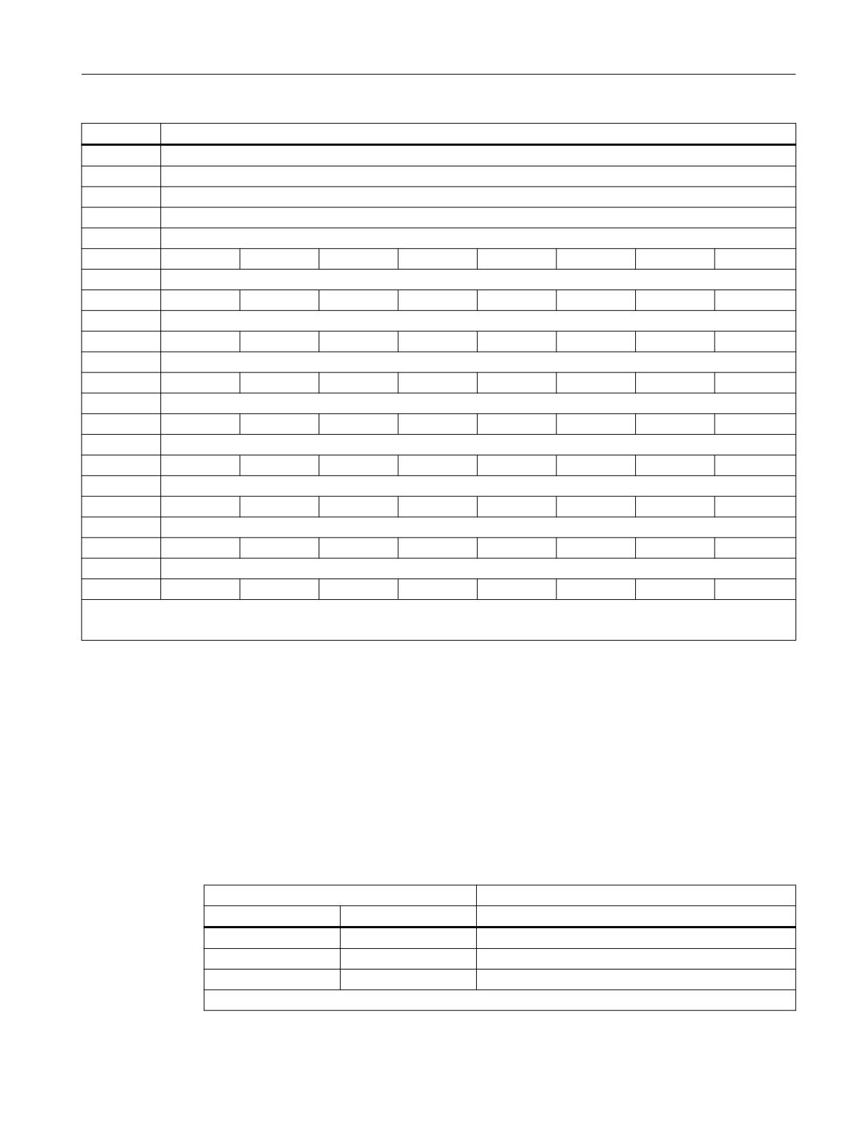
Data descriptions
9.6 Interface signals
DB 31...
Signals from/to the drive
DBB 112
Cam range for cam track 1
DBB 113
Cam range for cam track 2
DBB 114
Cam range for cam track 3
DBB 115
Cam range for cam track 4
DBB 116
DBB 117
Cam track 4
Cam track 3
Cam track 2
Cam track 1
Cam track 1
DBB 118
Cam 8
Cam 7
Cam 6
Cam 5
Cam 4
Cam 3
Cam 2
Cam 1
Cam track 1
DBB 119
Cam 15
Cam 14
Cam 13
Cam 12
Cam 11
Cam 10
Cam 9
Cam track 2
DBB 120
Cam 8
Cam 7
Cam 6
Cam 5
Cam 4
Cam 3
Cam 2
Cam 1
Cam track 2
DBB 121
Cam 15
Cam 14
Cam 13
Cam 12
Cam 11
Cam 10
Cam 9
Cam track 3
DBB 122
Cam 8
Cam 7
Cam 6
Cam 5
Cam 4
Cam 3
Cam 2
Cam 1
Cam track 3
DBB 123
Cam 15
Cam 14
Cam 13
Cam 12
Cam 11
Cam 10
Cam 9
Cam track 4
DBB 124
Cam 8
Cam 7
Cam 6
Cam 5
Cam 4
Cam 3
Cam 2
Cam 1
Cam track 4
DBB 125
Cam 15
Cam 14
Cam 13
Cam 12
Cam 11
Cam 10
Cam 9
Note:
DB 31 / 32 / 33 ... contains the interface signals for axis/spindle 1 / 2 / 3 ...
9.6.2
Description of the interface signal
Description of the signals sent to the monitoring channel
The individual signals that are transferred to the monitoring channel are listed in the following.
SGE, SBH/SG deselection, SBH deselection
The SBH and SG functions are selected/deselected using these signals.
SGE
Meaning
SBH/SG deselection
SBH deselection
= 1
x
SBH and SG are deselected
= 0
= 0
SBH is selected
= 0
= 1
SG is selected
x: Signal state is optional
Safety Integrated (system-integrated)
Function Manual, 10/2020, 6FC5397-4BP40-6BA2
471
Data descriptions
9.6 Interface signals
SGE SG selection, bits 1, 0
By combining these signals when the SG function is activated it is possible to select the speed
limit value for SG1, 2, 3 or 4.
SGE
Meaning
SG selection, bit 1
SG selection, bit 0
= 0
= 0
Speed limit value for SG1 is selected
= 0
= 1
Speed limit value for SG2 is selected
= 1
= 0
Speed limit value for SG3 is selected
= 1
= 1
Speed limit value for SG4 is selected
SGE gearbox ratio selection, bits 2, 1, 0
The combination of these signals determines the selected gearbox ratio 1, 2, ... ,8.
SGE gearbox ratio selection
Meaning
Bit 2
Bit 1
Bit 0
0
0
0
Gearbox stage 1 is selected
0
0
1
Gearbox stage 2 is selected
0
1
0
Gearbox stage 3 is selected
1
1
1
Gearbox stage 8 is selected
SGE SE selection
When this signal is appropriately activated, and the SE function is activated, either SE1 or SE2 is
selected.
0 signal: SE1 is selected
1 signal: SE2 is selected
SGE SG correction selection/override, bits 3, 2, 1, 0
16 overrides for the limit value of safely reduced speeds 2 and 4 can be defined using the SGEs.
This means that the limit values for SG2 and SG4 can be more finely graduated.
An override factor of between 1 and 100% can be assigned to the selected override using the
following machine data:
For 840D sl:
MD36932 $MA_SAFE_VELO_OVR_FACTOR[n]
For SINAMICS S120:
p9532[n]: SI Motion, override factor
Safety Integrated (system-integrated)
472
Function Manual, 10/2020, 6FC5397-4BP40-6BA2
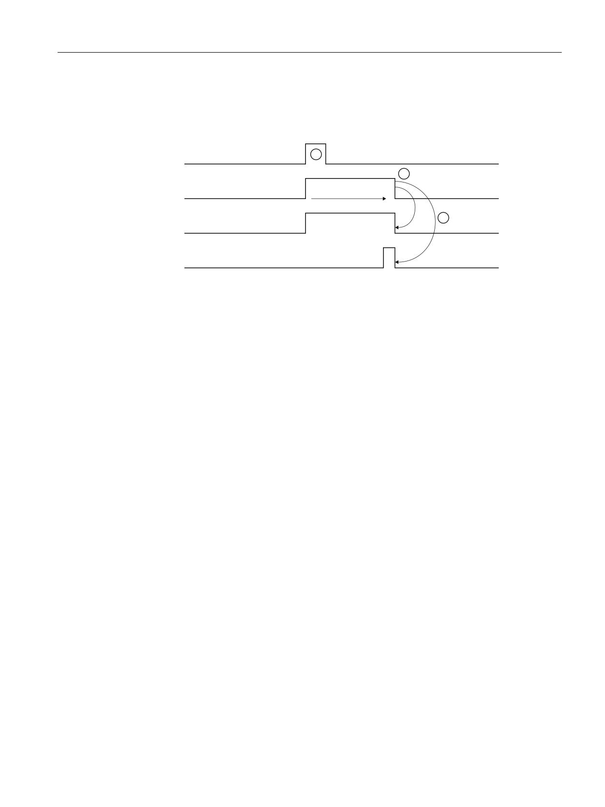
Data descriptions
9.6 Interface signals
SGE test stop selection
This signal is used to initiate the switch-off signal path test for the drive monitoring channel (see
Chapter "Switch-off signal paths (Page 103)").
6*( WHVW VWRS VHOHFWLRQ
7HVW VWRS UXQQLQJ RSHUDWLRQ
7LPHU DQG FKHFN
&DQFHO SXOVHV RSHUDWLRQ
6*$ 6WDWXV SXOVHV DUH FDQFHOOHG
① Pulse cancellation is started by setting the signal (1 PLC cycle).
② After the test stop has been started, a timer runs. When the time in the timer has expired, the test
stop execution is checked using the SGA "status, pulses cancelled".
③ The system resets the signals.
Figure 9-1
Signal timing for SGE test stop selection
The test stop is also carried out at the same time in the NCK monitoring channel (see Chapter
"Testing the switch-off signal paths (Page 105)").
Test stop for external STOPs
See Chapter "Forced checking procedure of the external STOPs (Page 130)".
SGE deselect ext. STOP A
"Pulse cancellation" can be requested and executed using this SGE.
The safe functions currently active (SG/SBH/SN/SE) are not influenced by this SGE.
If one of the currently active limits is violated, an appropriate alarm is initiated. The associated
shutdown response cannot be activated because the pulses have already been cancelled. As
soon as the stop request is cancelled via the SGE "deselect ext. STOP A" any queued shutdown
responses become active.
If a stop request is active, SGA "STOP A/B is active" is set in the same way as it would be for an
internally triggered STOP A.
0 signal: "Pulse cancellation" is requested
1 signal: "Pulse cancellation" is not requested
SGE deselect ext. STOP C
This SGE requests "braking with nset = 0" (braking along the OFF3 down ramp).
When this stopping type is initiated, the safe monitoring of the acceleration (SBR) is activated.
In addition, the timer set using MD36952/p9552: $MA_SAFE_STOP_SWITCH_TIME_C / "SI
Motion transition time STOP C to SBH" is started.
Safety Integrated (system-integrated)
Function Manual, 10/2020, 6FC5397-4BP40-6BA2
473
Data descriptions
9.6 Interface signals
After this time has elapsed, the system automatically changes over to SBH.
If a stop request is active, SGA "STOP C is active" is set in the same way as it would be for an
internally triggered STOP C.
0 signal: "Braking with nset = 0" is requested
1 signal: No request for "Braking with nset = 0"
Note
Stopping with an external STOP A (pulse cancellation) has a higher priority and can interrupt an
external STOP C (braking along the OFF3 down ramp).
SGE deselect ext. STOP D
"Braking along a path" can be requested using this SGE.
When ext. STOP D is triggered, the timer set using MD36953/p9553
$MA_SAFE_STOP_SWITCH_TIME_D / "SI Motion transition time STOP D to SBH" is started.
After this time has elapsed, the system automatically changes over to SBH.
If a stop request is active, SGA "STOP D is active" is set in the same way as it would be for an
internally triggered STOP D.
0 signal: "Braking along a path" is requested
1 signal: No request for "Braking along a path"
Note
Stopping with an external STOP A (pulse cancellation) and/or external STOP C (braking along the
OFF3 down ramp) has a higher priority and can interrupt an external STOP D (braking along a
path).
SGE deselect ext. STOP E
This SGE can be used to request a stop via the function "extended stopping and retraction" (ESR).
When an external STOP E is initiated the timer set using MD36954:
$MA_SAFE_STOP_SWITCH_TIME_E / p9554: Timer set for "SI Motion transition time STOP E to
SBH" is started.
After this time has elapsed, the system automatically changes over to SBH.
If a stop request is active, SGA "STOP E is active" is set in the same way as it would be for an
internally triggered STOP E.
0 signal: "Stop/retraction" is requested
Safety Integrated (system-integrated)
474
Function Manual, 10/2020, 6FC5397-4BP40-6BA2

Data descriptions
9.6 Interface signals
1 signal: "Stop/retract" is not requested
Note
Stopping with an external STOP A (pulse cancellation) and/or external STOP C (braking along the
OFF3 down ramp) and/or ext. STOP D (braking along a path) has/have a higher priority and can
interrupt an external STOP E.
STOP E only produces a different response than STOP D if the user has configured the ESR
function - extended stop and retract - and initiation of the ESR is programmed depending on
$VA_STOPSI or $A_STOPESI. If no ESR is active, the STOP E behaves like a STOP D. However, if the
ESR was incorrectly configured, there is a delay up to the time $MC_ESR_DELAY_TIME1 and
$MC_ESR_DELAY_TIME2 compared to STOP D until the braking operation is initiated.
After these times have expired, braking is initiated at the current limit.
Close SGE brake (only the drive)
Using this SGE, a mechanical brake, that is controlled from the drive brake control, is closed. It
is used to check brake closing while testing the mechanical brake system.
• If this SGE is set, the brake is closed.
• If this SGE is deleted, then the brake assumes the status of the drive brake control - i.e. it is
not forcibly opened (no positive opening).
Note
This SGE must be connected to the brake control using a BiCo interconnection in the drive
(p0858 to source r9719, bit 13). This connection is parameterized as standard.
"Selection of the velocity setpoint limit" control signals
MD36933 $MA_SAFE_DES_VELO_LIMIT contains 4 values:
The selection of one of these values is realized via the axis-specific PLC user interface
DB3x.DBX34.0...1.
Meaning of this interface:
Bit 0 "Setpoint limiting bit 0"
Bit 1 "Setpoint limiting bit 1"
Bit 0
Bit 1
Active setpoint limiting factor
= 0
= 0
SAFE_DES_VELO_LIMIT0
= 0
= 1
SAFE_DES_VELO_LIMIT1
= 1
= 0
SAFE_DES_VELO_LIMIT2
= 1
= 1
SAFE_DES_VELO_LIMIT3
"Axis is SI axis" status signal
DB3x.DBX70.4: "NCK Safety Integrated active"
Safety Integrated (system-integrated)
Function Manual, 10/2020, 6FC5397-4BP40-6BA2
475
Data descriptions
9.6 Interface signals
Description of signals from the monitoring channel
The individual signals that are transferred from the monitoring channel are listed in the
following.
SGA SBH/SG active
This signal is used to signal the drive monitoring channel the status of the SBH and SG functions
as follows:
0 signal: SBH/SG is not active
1 signal: SBH/SG is active
SGA status, pulses are cancelled (drive only)
After the switch-off signal path test has been initiated using the SGE test stop selection or if a
limit value is violated with a resulting STOP A response, this signal is output to indicate that the
drive pulses have been internally cancelled.
For all axes, the signal is initialized with the value "1"; for non-SI axes, the signal permanently
stays at a value of "1" (see Chapter "Switch-off signal paths (Page 103)".
Note
To identify as to whether an SI axis is available, the axis-specific signal "NCK Safety Integrated
active" can be evaluated.
0 signal: Pulses are enabled
1 signal: Pulses have been cancelled
SGA axis safely referenced
This indicates as to whether the relevant axis/spindle has been safely referenced (see Chapter
"Axis states (Page 90)").
0 signal: Axis is not safely referenced
1 signal: Axis is safely referenced
SGA SN1+, SN1-, SN2+, SN2-, SN3+, SN3-, SN4+, SN4-
These signals are used to indicate which of the plus or minus cams of cam pair 1, 2, 3 or 4 is
"actuated".
0 signal:
Axis/spindle is located to the left of the cam (actual value < cam position)
1 signal:
Axis/spindle is located to the right of the cam (actual value > cam position)
Safety Integrated (system-integrated)
476
Function Manual, 10/2020, 6FC5397-4BP40-6BA2
Data descriptions
9.6 Interface signals
SGA Safe Cam Track
This signal displays whether the axis is located on a cam that is assigned to this cam track (this
only applies to the "Safe Cam Track" function).
0 signal:
The axis is not located on a cam of this cam track
1 signal:
The axis is located on a cam of this cam track
SGA Safe Cam range
These bits (4 bits per cam track) display in which cam range the axis is presently located (this is
only valid for the "Safe Cam Track" function).
SGA Safe Cam range bits
This signal displays at which cam the axis is presently located (this is only valid for the "Safe Cam
Track" function).
0 signal: The axis is not located at this cam
1 signal: The axis is located at this cam
SGA SBH active
The signal indicates the status of the Safe Operating Stop (SBH).
1 signal: SBH is active
0 signal: SBH is not active
SGA STOP A/B is active
This signal indicates that STOP A/B is active.
The signal must be used for the forced checking procedure for external STOPs.
0 signal: STOP A/B is not active
1 signal: STOP A/B is active
SGA STOP C is active
This signal indicates that STOP C is active.
The signal must be used for the forced checking procedure for external STOPs.
0 signal: STOP C is not active
1 signal: STOP C is active
Safety Integrated (system-integrated)
Function Manual, 10/2020, 6FC5397-4BP40-6BA2
477
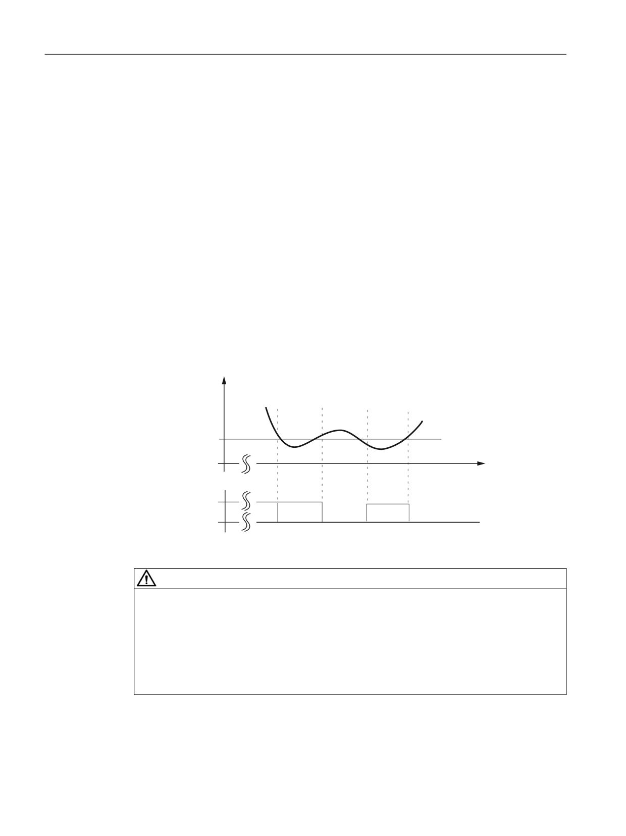
Data descriptions
9.6 Interface signals
SGA STOP D is active
This signal indicates that STOP D is active.
The signal must be used for the forced checking procedure for external STOPs.
0 signal: STOP D is not active
1 signal: STOP D is active
SGA STOP E is active
This signal indicates that STOP E is active.
The signal must be used for the forced checking procedure for external STOPs.
0 signal: STOP E is not active
1 signal: STOP E is active
SGA "n < nx
This SGA indicates whether the absolute value of the actual speed is above or below a speed
specified in the machine data.
Q
Q[
W
6*$ Q Q[
Figure 9-2
Signal n < nx, dependent on the speed characteristic
WARNING
Functions SBH, SG, SE, SN
A STOP F (displayed using Alarms 27001, 27101 and onwards or F01711) only results in a
subsequent STOP B/A response, if at least one of the safety-related functions SBH, SG, SE, SN
or n<nx synchronization is active or selected. If only the function "n < nx" is active, then a STOP
F does not result in a subsequent STOP B/A response.
This means that if "n<nx" is used as a safety function, then at least one of the SBH, SG, SE, SN
functions must be active or selected (e.g. by selecting a high SG level).
Safety Integrated (system-integrated)
478
Function Manual, 10/2020, 6FC5397-4BP40-6BA2

Data descriptions
9.6 Interface signals
Note
If the axis/spindle runs at a speed nx, then as a result of actual differences in the two monitoring
channels, the SGA "n < nx" can have different states.
This must be taken into account in the safe processing of the SGA.
SG active, bits 0, 1
The SGA "SG active bits 1, 0" displays which safely reduced speed and therefore which speed limit
value is actively monitored. The SGAs are only updated if the function "SBH/SG" is enabled and
SG is active (SGE "SBH/SG deselection" = 0 and "SBH deselection" = 1).
SGA
Meaning
SG ac-
SG ac-
SBH/
SBH ac-
tive
tive
SG ac-
tive
bit 1
bit 0
tive
= 0
= 0
1
1
SBH is active (safely reduced speed is not active)
= 0
= 0
1
0
Speed limit value for SG1 active
= 0
= 1
1
0
Speed limit value for SG2 active
= 1
= 0
1
0
Speed limit value for SG3 active
= 1
= 1
1
0
Speed limit value for SG4 active
= 0
= 0
0
0
Neither SBH nor SG is active
Note:
The state "SG active bits 1, 0" = "0" has different meanings. A clear interpretation can be obtained by additionally evaluating the
SGAs "SBH active" and "SBH/SG active".
Communication failure
For a sign-of-life error or CRC error, this signal is set to TRUE. The PLC-SPL remains functional in
so much that the drive monitoring channel is not required. SGE to the drive are not effective. The
SGA from the drive are frozen at the state before communications failed.
Response time of the PLC when the sign of life character from the drive fails: 3 s
Response time of the PLC for CRC errors from the drive: 1 PLC cycles
Ongoing behavior depends on the bit "Acknowledgment communication failure". The fault
situation can only be executed with POWER ON.
Fault, data transfer
This signal is used to diagnose the cause for the set signal "communication error".
1 signal: There is a CRC error
0 signal: There is no CRC error
Safety Integrated (system-integrated)
Function Manual, 10/2020, 6FC5397-4BP40-6BA2
479
Data descriptions
9.6 Interface signals
Acknowledgment, communication failure
It is possible to acknowledge faults that are displayed via the "communication failure" bit using
the "acknowledgment communication failure" signal. This acknowledgment must be made in
the same OB1 cycle as when the "communication failure" signal occurred as 0/1 edge.
WARNING
Setting the acknowledgment
When setting the acknowledgment, the user assumes the responsibility of providing suitable
substitute values for the SGA of the drive, as these are no longer valid. The user must bring the
machine into a safe state.
If the acknowledgment is not made after an OB1 cycle, then the frozen SGA are changed over
from the drive to deleted SGA and the diagnostics bit "Communication failure was not
acknowledged" is set. If the acknowledgment is made within an OB1 cycle, the SGA of the drive
remain frozen and the diagnostics bit "Communication failure was not acknowledged" is not set.
There is no further response.
The fault situation can only be executed with POWER ON.
Communication failure was not acknowledged
Indicates whether a fault displayed using bit "Communication failure" was acknowledged using
the bit "Acknowledge communication failure":
0: Communication has not failed or a communication failure was acknowledged.
1: Communication has failed and this was not acknowledged.
9.6.3
PLC data block (DB18)
Parameterization part
DB18
Signals for safety SPL
Data block
Interface PLC → PLC
Byte
Bit 7
Bit 6
Bit 5
Bit 4
Bit 3
Bit 2
Bit 1
Bit 0
INSEP valid (valid bit)
DBB 0
8th input
7th input
6th input
5th input
4th input
3rd input
2nd input
1st input
byte
byte
byte
byte
byte
byte
byte
byte
DBB1
OUTSEPValid (valid bit)
DBB 2
8th output
7th output
6th output
5th output
4th output
3rd output
2nd output
1st output
byte
byte
byte
byte
byte
byte
byte
byte
DBB 3
Safety Integrated (system-integrated)
480
Function Manual, 10/2020, 6FC5397-4BP40-6BA2

Data descriptions
9.6 Interface signals
DB18
Signals for safety SPL
INSEP_ADDR (address 1st input byte)
DBW4
INSEP_ADDR (address 2nd input byte)
DBW6
INSEP_ADDR (address 3rd input byte)
DBW8
INSEP_ADDR (address 4th input byte)
DBW10
INSEP_ADDR (address 5th input byte)
DBW12
INSEP_ADDR (address 6th input byte)
DBW14
INSEP_ADDR (address 7th input byte)
DBW16
INSEP_ADDR (address 8th input byte)
DBW18
OUTSEP_ADDR (address 1st output byte)
DBW20
OUTSEP_ADDR (address 2nd output byte)
DBW22
OUTSEP_ADDR (address 3rd output byte)
DBW24
OUTSEP_ADDR (address 4th output byte)
DBW26
OUTSEP_ADDR (address 5th output byte)
DBW28
OUTSEP_ADDR (address 6th output byte)
DBW30
OUTSEP_ADDR (address 7th output byte)
DBW32
OUTSEP_ADDR (address 8th output byte)
DBW34
DBB36
STOP_E
SPL_READY
DBB37
Note
DBB0-35 is not relevant for SINUMERIK 840D sl.
Safety Integrated (system-integrated)
Function Manual, 10/2020, 6FC5397-4BP40-6BA2
481

Data descriptions
9.6 Interface signals
Data area/errors
DB18
Signals for safety SPL
Data block
PLC → NCK interface
Byte
Bit 7
Bit 6
Bit 5
Bit 4
Bit 3
Bit 2
Bit 1
Bit 0
Data area of the SPL inputs/outputs
SPL_DATA.INSEP[1 ...32]
DBB 38...41
SPL_DATA.INSEP[33 ...64]
DBB 42...45
SPL_DATA.OUTSEP[1 ...32]
DBB 46...49
SPL_DATA.OUTSEP[33 ...64]
DBB 50...53
Data area for user SPL
SPL_DATA.INSIP[1 ...32]
DBB 54...57
SPL_DATA.INSIP[33 ...64]
DBB 58...61
SPL_DATA.OUTSIP[1 ...32]
DBB 62...65
SPL_DATA.OUTSIP[33 ...64]
DBB 66...69
SPL_DATA.MARKERSIP[1 ...32]
DBB 70...73
SPL_DATA.MARKERSIP[33 ...64]
DBB 74...77
Signal level difference NCK PLC for diagnostics
SPL_DELTA.INSEP[1 ...32]
DBB 78...81
SPL_DELTA.INSEP[33 ...64]
DBD 82...85
SPL_DELTA.OUTSEP[1 ...32]
DBB 86
SPL_DELTA.OUTSEP[33 ...64]
DBB 90...93
SPL_DELTA.INSIP[1 ...32]
DBB 94...97
SPL_DELTA.INSIP[33 ...64]
DBB
98...101
SPL_DELTA.OUTSIP[1 ...32]
DBB
102...105
Safety Integrated (system-integrated)
482
Function Manual, 10/2020, 6FC5397-4BP40-6BA2

Data descriptions
9.6 Interface signals
DB18
Signals for safety SPL
SPL_DELTA.OUTSIP[33 ...64]
DBB
106...109
SPL_DELTA.MARKERSIP[1 ...32]
DBB
110...113
SPL_DELTA.MARKERSIP[33 ...64]
DBB
114...117
DBB 118
CMDSI
DBB 119
NCK signals
System error,
CDC error
PROFIsafe
a STOP to
crosswise da-
"SPL protec-
communi-
the PLC.
ta comparison
tion status"
cation error
DBB 120
STATSI
Crosswise data comparison error initiated if the value is not equal to 0
DBB 124
LEVELSI
CDC stack level display
(diagnostics capability: How many SPL signals currently have different levels)
Additional data areas
DB18
Signals for safety SPL
Data block
PLC → NCK interface
Byte
Bit 7
Bit 6
Bit 5
Bit 4
Bit 3
Bit 2
Bit 1
Bit 0
Data area of the single-channel inputs/outputs
PLCSIOUT[1 ...8]
From NCK
DBB128
PLCSIOUT[9 ...16]
From NCK
DBB129
PLCSIOUT[17 ..24]
From NCK
DBB130
PLCSIOUT[25 ...32]
From NCK
DBB131
PLCSIIN[1 ...8]
to the NCK
DBB132
PLCSIIN[9 ...16]
to the NCK
DBB133
PLCSIIN[17 ...24]
Safety Integrated (system-integrated)
Function Manual, 10/2020, 6FC5397-4BP40-6BA2
483
Data descriptions
9.6 Interface signals
DB18
Signals for safety SPL
to the NCK
DBB134
PLCSIIN[25 ...32]
to the NCK
DBB135
SPL status[1 ...16]
DBB136...
137
INSEP_PROFISAFE[1 ...8] PROFIsafe module(s) for
DBB138
8th input
7th input
6th input
5th input
4th input
3rd input
2nd input
1st input
byte
byte
byte
byte
byte
byte
byte
byte
DBB139
OUTSEP_PROFISAFE[1 ...8] PROFIsafe module(s) for
DBB140
8th output
7th output
6th output
5th output
4th output
3rd output
2nd output
1st output
byte
byte
byte
byte
byte
byte
byte
byte
DBB141
DBB142
to
DBB149
DBB150
to
DBB157
DBB158
to
DBB188
F_SENDDP (sender)
DB18
F_SENDDP 1...3
Data block
PLC → NCK interface
Byte
Bit 7
Bit 6
Bit 5
Bit 4
Bit 3
Bit 2
Bit 1
Bit 0
DBW190
FSDP[1].ERR_REAC
DBB192
FSDP[1].
FSDP[1].
SUBS_ON
ERROR
DBB193
DBB194
FSDP[1].DIAG
DBB196
FSDP[1].RETVAL14
Safety Integrated (system-integrated)
484
Function Manual, 10/2020, 6FC5397-4BP40-6BA2

Data descriptions
9.6 Interface signals
DB18
F_SENDDP 1...3
DBW198
FSDP[1].RETVAL15
DBW200
FSDP[2].ERR_REAC
DBB202
FSDP[2].
FSDP[2].
SUBS_ON
ERROR
DBB203
DBW204
FSDP[2].DIAG
DBW206
FSDP[2].RETVAL14
DBW208
FSDP[2].RETVAL15
DBW210
FSDP[3].ERR_REAC
DBB212
FSDP[3].
FSDP[23.
SUBS_ON
ERROR
DBB213
DBW214
FSDP[3].DIAG
DBW216
FSDP[3].RETVAL14
DBW218
FSDP[3].RETVAL15
DB18
F_SENDDP 4...16
Data block
PLC → NCK interface
Byte
Bit 7
Bit 6
Bit 5
Bit 4
Bit 3
Bit 2
Bit 1
Bit 0
DBW448
FSDP HF[4].ERR_REAC
DBB450
FSDP HF[4].
FSD HF[4].
SUBS_ON
ERROR
DBB451
DBB452
FSDP_HF[4].DIAG
DBB454
FSDP_HF[4].RETVAL14
DBW456
FSDP_HF[4].RETVAL15
Safety Integrated (system-integrated)
Function Manual, 10/2020, 6FC5397-4BP40-6BA2
485

Data descriptions
9.6 Interface signals
DB18
F_SENDDP 4...16
DBW448
FSDP HF[5].ERR_REAC
DBB450
FSDP HF[5].
FSDP HF[5].
SUBS_ON
ERROR
DBB451
DBW452
FSDP_HF[5].DIAG
DBW454
FSDP_HF[5].RETVAL14
DBW456
FSDP_HF[5].RETVAL15
DBW568
FSDP_HF[16].ERR_REAC
DBB570
FSDP
FSDP
HF[16].
HF[16].
SUBS_ON
ERROR
DBB571
DBW572
FSDP_HF[16].DIAG
DBW574
FSDP_HF[16].RETVAL14
DBW576
FSDP_HF[16].RETVAL15
F_RECVDP (receiver)
DB18
F_RECVDP 1...3
Data block
PLC → NCK interface
Byte
Bit 7
Bit 6
Bit 5
Bit 4
Bit 3
Bit 2
Bit 1
Bit 0
DBB220
FRDP[1].
FRDP[1].
FRDP[1].
FRDP[1].
FRDP[1].
FRDP[1].
FRDP[1].
FRDP[1].
SUBS[7]
SUBS[6]
SUBS[5]
SUBS[4]
SUBS[3]
SUBS[2]
SUBS[1]
SUBS[0]
DBB221
FRDP[1].
FRDP[1].
FRDP[1].
FRDP[1].
FRDP[1].
FRDP[1].
FRDP[1].
FRDP[1].
SUBS[15]
SUBS[14]
SUBS[13]
SUBS[12]
SUBS[11]
SUBS[10]
SUBS[9]
SUBS[8]
DBB222
FRDP[1].ERR_REAC
DBB224
FRDP[1].
ACK_REI
DBB225
FRDP[1].
FRDP[1].
FRDP[1].
FRDP[1].
SENDMODE
ACK_REQ
SUBS_ON
ERROR
DBW226
FRDP[1].DIAG
Safety Integrated (system-integrated)
486
Function Manual, 10/2020, 6FC5397-4BP40-6BA2