SINUMERIK 840D sl. Service - Safety Integrated. Manual (2020) - page 8

Data descriptions
9.6 Interface signals
DB18
F_RECVDP 1...3
DBW228
FRDP[1].RETVAL14
DBW230
FRDP[1].RETVAL15
DBB232
FRDP[2].
FRDP[2].
FRDP[2].
FRDP[2].
FRDP[2].
FRDP[2].
FRDP[2].
FRDP[2].
SUBS[7]
SUBS[6]
SUBS[5]
SUBS[4]
SUBS[3]
SUBS[2]
SUBS[1]
SUBS[0]
DBB233
FRDP[2].
FRDP[2].
FRDP[2].
FRDP[2].
FRDP[2].
FRDP[2].
FRDP[2].
FRDP[2].
SUBS[15]
SUBS[14]
SUBS[13]
SUBS[12]
SUBS[11]
SUBS[10]
SUBS[9]
SUBS[8]
DBW234
FRDP[2].ERR REAC
DBB236
FRDP[2].
ACK_REI
DBB237
FRDP[2].
FRDP[2].
FRDP[2].
FRDP[2].
SENDMODE
ACK_REQ
SUBS_ON
ERROR
DBW238
FRDP[2].DIAG
DBW240
FRDP[2].RETVAL14
DBW242
FRDP[2].RETVAL15
DBB244
FRDP[3].
FRDP[3].
FRDP[3].
FRDP[3].
FRDP[3].
FRDP[3].
FRDP[3].
FRDP[3].
SUBS[7]
SUBS[6]
SUBS[5]
SUBS[4]
SUBS[3]
SUBS[2]
SUBS[1]
SUBS[0]
DBB245
FRDP[3].
FRDP[3].
FRDP[3].
FRDP[3].
FRDP[3].
FRDP[3].
FRDP[3].
FRDP[3].
SUBS[15]
SUBS[14]
SUBS[13]
SUBS[12]
SUBS[11]
SUBS[10]
SUBS[9]
SUBS[8]
DBW246
FRDP[3].ERR REAC
DBB248
FRDP[3].
ACK_REI
DBB249
FRDP[3].
FRDP[3].
FRDP[3].
FRDP[3].
SENDMODE
ACK_REQ
SUBS_ON
ERROR
DBW250
FRDP[3].DIAG
DBW252
FRDP[3].RETVAL14
DBW254
FRDP[3].RETVAL15
DBD256
SPL USER DATA[0]
DBD260
SPL USER DATA[1]
Safety Integrated (system-integrated)
Function Manual, 10/2020, 6FC5397-4BP40-6BA2
487
Data descriptions
9.6 Interface signals
DB18
F_RECVDP 1...3
DBD264
SPL USER DATA[2]
DBD268
SPL USER DATA[3]
DB18
F_RECVDP 4...16
Data block
PLC → NCK interface
Byte
Bit 7
Bit 6
Bit 5
Bit 4
Bit 3
Bit 2
Bit 1
Bit 0
DBB578
FRDP HF[4].
FRDP HF[4].
FRDP HF[4].
FRDP HF[4].
FRDP HF[4].
FRDP HF[4].
FRDP HF[4].
FRDP HF[4].
SUBS[7]
SUBS[6]
SUBS[5]
SUBS[4]
SUBS[3]
SUBS[2]
SUBS[1]
SUBS[0]
DBB579
FRDP HF[4].
FRDP HF[4].
FRDP HF[4].
FRDP HF[4].
FRDP HF[4].
FRDP HF[4].
FRDP HF[4].
FRDP HF[4].
SUBS[15]
SUBS[14]
SUBS[13]
SUBS[12]
SUBS[11]
SUBS[10]
SUBS[9]
SUBS[8]
DBW580
FRDP HF[4].ERR_REAC
DBB582
FRDP HF[4].
ACK_REI
DBB583
FRDP HF[4].
FRDP HF[4].
FRDP HF[4].
FRDP HF[4].
SENDMODE
ACK_REQ
SUBS_ON
ERROR
DBW584
FRDP HF[4].DIAG
DBW586
FRDP HF[4].RETVAL14
DBW588
FRDP HF[4].RETVAL15
DBB590
FRDP HF[5].
FRDP HF[5].
FRDP HF[5].
FRDP HF[5].
FRDP HF[5].
FRDP HF[5].
FRDP HF[5].
FRDP HF[5].
SUBS[7]
SUBS[6]
SUBS[5]
SUBS[4]
SUBS[3]
SUBS[2]
SUBS[1]
SUBS[0]
DBB591
FRDP HF[5].
FRDP HF[5].
FRDP HF[5].
FRDP HF[5].
FRDP HF[5].
FRDP HF[5].
FRDP HF[5].
FRDP HF[5].
SUBS[15]
SUBS[14]
SUBS[13]
SUBS[12]
SUBS[11]
SUBS[10]
SUBS[9]
SUBS[8]
DBW592
FRDP HF[5].ERR_REAC
DBB594
FRDP HF[5].
ACK_REI
DBB595
FRDP HF[5].
FRDP HF[5].
FRDP HF[5].
FRDP HF[5].
SENDMODE
ACK_REQ
SUBS_ON
ERROR
DBW596
FRDP HF[5].DIAG
DBW598
FRDP HF[5].RETVAL14
DBW600
FRDP HF[5].RETVAL15
DBB722
FRDP
FRDP
FRDP
FRDP
FRDP
FRDP
FRDP
FRDP
HF[16].
HF[16].
HF[16].
HF[16].
HF[16].
HF[16].
HF[16].
HF[16].
SUBS[7]
SUBS[6]
SUBS[5]
SUBS[4]
SUBS[3]
SUBS[2]
SUBS[1]
SUBS[0]
DBB723
FRDP
FRDP
FRDP
FRDP
FRDP
FRDP
FRDP
FRDP
HF[16].
HF[16].
HF[16].
HF[16].
HF[16].
HF[16].
HF[16].
HF[16].
SUBS[15]
SUBS[14]
SUBS[13]
SUBS[12]
SUBS[11]
SUBS[10]
SUBS[9]
SUBS[8]
DBW724
FRDP HF[16].ERR_REAC
Safety Integrated (system-integrated)
488
Function Manual, 10/2020, 6FC5397-4BP40-6BA2
Data descriptions
9.6 Interface signals
DB18
F_RECVDP 4...16
DBB726
FRDP
HF[16].
ACK_REI
DBB727
FRDP
FRDP
FRDP
FRDP
HF[16].
HF[16].
HF[16].
HF[16].
SENDMODE
ACK_REQ
SUBS_ON
ERROR
DBW728
FRDP HF[16].DIAG
DBW730
FRDP HF[16].RETVAL14
DBW732
FRDP HF[16].RETVAL15
Data area / errors (extended data area)
DB18
Signals for safety SPL
Data block
PLC → NCK interface
Byte
Bit 7
Bit 6
Bit 5
Bit 4
Bit 3
Bit 2
Bit 1
Bit 0
DBB272...
SPL_DATA_HF.INSEP[65...96]
275
DBB276...
SPL_DATA_HF.INSEP[97...128]
279
DBB280...
SPL_DATA_HF.INSEP[129...160]
283
DBB284...
SPL_DATA_HF.INSEP[161...192]
287
DBB288...
SPL_DATA_HF.OUTSEP[65...96]
291
DB292...2
SPL_DATA_HF.OUTSEP[97...128]
95
DB296...2
SPL_DATA_HF.OUTSEP[129...160],
99
DBB300...
SPL_DATA_HF.OUTSEP[161...192],
303
,
Data area for user SPL
DBB304...
SPL_DATA_HF.INSIP[65...96]
307
Safety Integrated (system-integrated)
Function Manual, 10/2020, 6FC5397-4BP40-6BA2
489

Data descriptions
9.6 Interface signals
DB18
Signals for safety SPL
DBB308...
SPL_DATA_HF.INSIP[97...128],
311
DBB312...
SPL_DATA_HF.INSIP[129...160]
315
DBB316...
SPL_DATA_HF.INSIP[161...192]
319
DBB320...
SPL_DATA_HF.OUTSIP[65...96]
323
DBB324...
SPL_DATA_HF.OUTSIP[97...128]
327
DBB328...
SPL_DATA_HF.OUTSIP[129...160]
331
DBB332...
SPL_DATA_HF.OUTSIP[161...192]
335
DBB336...
SPL_DATA_HF.MARKERSIP[65...96]...
339
DBB340...
SPL_DATA_HF.MARKERSIP[97...128]
343
DBB344...
SPL_DATA_HF.MARKERSIP[129...160]
347
DBW348...
SPL_DATA_HF.MARKERSIP[161...192]
351
Difference in signal level NCK - PLC for diagnostics
DBB352...
SPL_DELTA_HF.INSEP[65...96]
355
DBB356...
SPL_DELTA_HF.INSEP[97...128]
359
DBB360...
SPL_DELTA_HF.INSEP[129...160]
363
DBB364...
SPL_DELTA_HF.INSEP[161...192]
367
DBB368...
SPL_DELTA_HF.OUTSEP[65...96]
371
Safety Integrated (system-integrated)
490
Function Manual, 10/2020, 6FC5397-4BP40-6BA2

Data descriptions
9.6 Interface signals
DB18
Signals for safety SPL
DBB372...
SPL_DELTA_HF.OUTSEP[97...128]
375
DBB376...
SPL_DELTA_HF.OUTSEP[129...160]
379
DBB380...
SPL_DELTA_HF.OUTSEP[161...192]
383
DBB384...
SPL_DELTA_HF.INSIP[65...96]
387
DBB388...
SPL_DELTA_HF.INSIP[97...128]
391
DBB392...
SPL_DELTA_HF.INSIP[129...160]
395
DBB396...
SPL_DELTA_HF.INSIP[161...192]
399
DBB400...
SPL_DELTA_HF.OUTSIP[65...96]
403
DBB404...
SPL_DELTA_HF.OUTSIP[97...128]
407
DBB408...
SPL_DELTA_HF.OUTSIP[129...160]
411
DBB412...
SPL_DELTA_HF.OUTSIP[161...192]
415
DBB416...
SPL_DELTA_HF.MARKERSIP[65...96]
419
DBB420...
SPL_DELTA_HF.MARKERSIP[97...128]
423
DBB424...
SPL_DELTA_HF.MARKERSIP[129...160]
427
DBB428...
SPL_DELTA_HF.MARKERSIP[161...192]
431
Additional data areas (extended data area)
DB 18
Signals for safety SPL
Data block
PLC → NCK interface
Byte
Bit 7
Bit 6
Bit 5
Bit 4
Bit 3
Bit 2
Bit 1
Bit 0
Data area of the single-channel inputs/outputs
From NCK
PLCSIOUT_HF[33...40]
DBB432
Safety Integrated (system-integrated)
Function Manual, 10/2020, 6FC5397-4BP40-6BA2
491
Data descriptions
9.6 Interface signals
DB 18
Signals for safety SPL
From NCK
PLCSIOUT_HF[41...48]
DBB433
From NCK
PLCSIOUT_HF[49...56]
DBB434
From NCK
PLCSIOUT_HF[57...64]
DBB435
From NCK
PLCSIOUT_HF[65...72]
DBB436
From NCK
PLCSIOUT_HF[73...80]
DBB437
From NCK
PLCSIOUT_HF[81...88]
DBB438
From NCK
PLCSIOUT_HF[89...96]
DBB439
From NCK
PLCSIIN_HF[33...40]
DBB440
From NCK
PLCSIIN_HF[41...48)
DBB441
From NCK
PLCSIIN_HF[49...56]
DBB442
From NCK
PLCSIIN_HF[57...64]
DBB443
From NCK
PLCSIIN_HF[65...72]
DBB444
From NCK
PLCSIIN_HF[73...80]
DBB445
From NCK
PLCSIIN_HF[81...88]
DBB446
From NCK
PLCSIIN_HF[89...96]
DBB447
SPL status signals for DB18.DBW136
DB18.DBX136.0
SPL_STATUS[1]
NCK-SPL interfaces parameterized
DB18.DBX136.1
SPL_STATUS[2]
NCK-SPL program file exists
DB18.DBX136.2
SPL_STATUS[3]
NCK waits for the PLC to boot
DB18.DBX136.3
SPL_STATUS[4]
NCK and PLC in cyclic operation
DB18.DBX136.4
SPL_STATUS[5]
Call FB4 processing for SPL
DB18.DBX136.5
SPL_STATUS[6]
Exit FB4 processing for SPL
DB18.DBX136.6
SPL_STATUS[7]
Call FC9 processing for SPL
DB18.DBX136.7
SPL_STATUS[8]
Exit FC9 processing for SPL
DB18.DBX137.0
SPL_STATUS[9]
SPL start implemented using PROG_EVENT mechanism
DB18.DBX137.1
SPL_STATUS[10]
Crosswise data comparison started, NCK
Safety Integrated (system-integrated)
492
Function Manual, 10/2020, 6FC5397-4BP40-6BA2
Data descriptions
9.6 Interface signals
DB18.DBX137.2
SPL_STATUS[11]
Crosswise data comparison started, PLC
DB18.DBX137.3
SPL_STATUS[12]
NCK-SPL checksum checking active
DB18.DBX137.4
SPL_STATUS[13]
All SPL protective mechanisms active
DB18.DBX137.5
SPL_STATUS[14]
End of SPL program reached
DB18.DBX137.6
SPL_STATUS[15]
SPL started with power on
DB18.DBX137.7
SPL_STATUS[16]
Not assigned
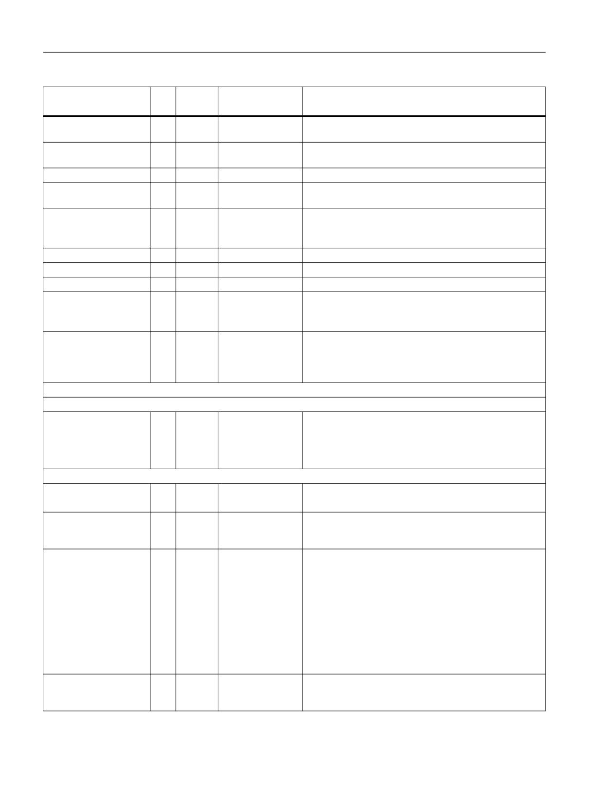
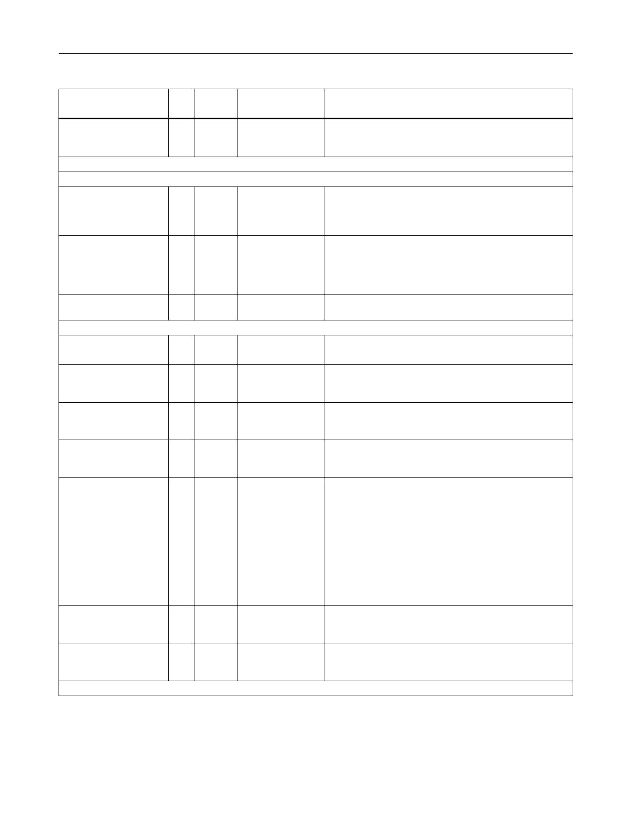
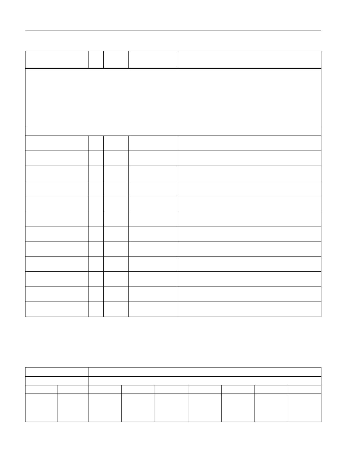
Table 9-4
Overview of DB18 signals
DB18
r/w
Type
Value range
Remark
Signal
Parameterization part
INSEP_VALID[1..8]
r/w
Bool
Address, input byte
(no significance)
OUTSEP_VALID[1..8]
r/w
Bool
Address, output byte
(no significance)
INSEP_ADDR[1..8]
r/w
Int
1..EB max
Address, input byte
(no significance)
OUTSEP_ADDR[1..8]
r/w
Int
1..AB max
Address, output byte
(no significance)
SPL_READY
r/w
Bool
0 = commissioning phase (for CDC error, no STOP D is initi-
ated)
1 = commissioning completed (for CDC error, STOP D initi-
ated)
STOP_MODE
r/w
Bool
If DB18, DBX36.1 was set to 1, for a crosswise data compar-
ison error, instead of an external STOP D, an external STOP E
is transferred to the drive
Data area/status
SPL_DATA
Net (useful) data:
INSEP[1..192]
r
Bool
External PLC input for the SPL
OUTSEP[1..192]
r/w
Bool
External PLC output for the SPL
INSIP[1..192]
r
Bool
Internal PLC input for the SPL
OUTSIP[1..192]
r/w
Bool
Internal PLC output for the SPL
MARKERSIP[1..192]
r/w
Bool
Marker for SPL
SPL_DELTA
Signal differences for diagnostics:
INSEP[1..192]
r
Bool
External PLC input for the SPL
OUTSEP[1..192]
r
Bool
External PLC output for the SPL
INSIP[1..192]
r
Bool
Internal PLC input for the SPL
OUTSIP[1..192]
r
Bool
Internal PLC output for the SPL
MARKERSIP[1..192]
r
Bool
Marker for SPL
CMDSI
r/w
Bool
The timeout value in the crosswise data comparison is ex-
tended by a factor of 10
PS_FEHL
r
Bool
PS-communication error, in conjunction with PROFIsafe, an
error is signaled
Safety Integrated (system-integrated)
Function Manual, 10/2020, 6FC5397-4BP40-6BA2
493
Data descriptions
9.6 Interface signals
DB18
r/w
Type
Value range
Remark
Signal
COMM_FAULT
r
Bool
CDC error "SPL protection status" (Status NC: $MN_PRE-
VENT_SYNACT_LOCK not equal to PLC: SPL_READY)
COMM_TO
r
Bool
0 -> 1 communication timeout detected, PLC will go into
stop in 5 s
STOP_FROM_NC
r
Bool
NCK signals a stop to the PLC.
STATSI
r
Dint
0 - 320
crosswise data comparison error if the value is not equal to
0
LEVELSI
r
Dint
CDC stack level display
(diagnostics capability: How many SPL signals currently
have different levels)
PLCSIIN[1 ..32]
r/w
Bool
Single-channel signals from the PLC to NCK
PLCSIOUT[1 ..32]
r
Bool
Single-channel signals from the NCK to the PLC
SPL_STATUS
r
Bool
Status signals from NCK to PLC
INSEP_PROFISAFE
r
Bool
0 = no assignment from PROFIsafe F modules to INSEP [1..8]
1 = transfer from PROFIsafe F module to INSEP [1..8] using
the basic program
OUTSEP_PROFISAFE
r
Bool
0 = no assignment from PROFIsafe F modules to OUTSEP
[1..8]
1 = transfer from OUTSEP [1..8] to PROFIsafe F module using
the basic program
F_SENDDP
Inputs
FSDP[1..3].ERR_REAC
r/w
Int
0, 1, 2, 3
0 = Alarm 27350 + Stop D/E
FSDP_HF[4..16].ERR_RE-
1 = Alarm 27350
AC
2 = Alarm 27351 (only display, self-clearing)
3 = no system response
Outputs
FSDP[1..3].ERROR
r
Bool
TRUE/FALSE
0 = normal mode
FSDP_HF[4..16].ERROR
1 = communication error
FSDP[1..3].SUBS_ON
r
Bool
TRUE/FALSE
0 = output of process values
FSDP_HF[4..16].SUBS_O
1 = output of substitute values
N
FSDP[1..3].DIAG
r
Word
2#0000_0000_
Bit 0-3: Reserved
FSDP_HF[4..16].DIAG
0000_0000
Bit 4: 1 = timeout detected
-
Bit 5: 1 = sequence number error detected
2#1110_0000_0
Bit 6: 1 = CRC error detected
111_0000
Bit 7-12: Reserved
Bit 13: 1 = discrepancies in the F telegram data (telegram
discrepancy)
Bit 14: 1 = sign-of-life monitoring (LifeSign)
Bit 15: 1 = asynchronous fault state (StateFault)
FSDP[1..3].RETVAL14
r
Word
Error code of the SFC 14 (description of the error codes in the
FSDP_HF[4..16].RE-
online help for SFC 14)
TVAL14
Safety Integrated (system-integrated)
494
Function Manual, 10/2020, 6FC5397-4BP40-6BA2
Data descriptions
9.6 Interface signals
DB18
r/w
Type
Value range
Remark
Signal
FSDP[1..3].RETVAL15
r
Word
Error code of the SFC 15 (description of the error codes in the
FSDP_HF[4..16].RE-
online help for SFC 15)
TVAL15
F_RECVDP
Inputs
FRDP[1..3].SUBS_ON[0..
r/w
Bool
TRUE/FALSE
Substitute values for SPL input data
15]
FRDP_HF[4..16].SUBS_O
N[0..1 5]
FRDP[1..3].ERR_REAC
r/w
Int
0, 1, 2, 3
0 = Alarm 27350 + Stop D/E
FRDP_HF[4..16].ERR_RE-
1 = Alarm 27350
AC
2 = Alarm 27351 (only display, self-clearing)
3 = no system response
FRDP[1..3].ACK_REI
r/w
Bool
TRUE/FALSE
1 = user acknowledgment
FRDP_HF[4..16].ACK_REI
Outputs
FRDP[1..3].ERROR
r
Bool
TRUE/FALSE
0 = normal mode
FRDP_HF[4..16].ERROR
1 = communication error
FRDP[1..3].SUBS_ON
r
Bool
TRUE/FALSE
0 = output of process values
FRDP_HF[4..16].SUBS_O
1 = output of substitute values
N
FRDP[1..3].ACK_REQ
r
Bool
TRUE/FALSE
1 = user acknowledgment required
FRDP_HF[4..16].ACK_RE
Q
FRDP[1..3].SENDMODE
r
Bool
TRUE/FALSE
1 = F_CPU of the sender in deactivated safety operation
FRDP_HF[4..16].SEND-
MODE
FRDP[..3].DIAG
r
Word
2#0000_0000_
Bit 0-3: Reserved
FRDP_HF[4..16].DIAG
0000_0000
Bit 4: 1 = timeout detected
-
Bit 5: 1 = sequence number error detected
2#1110_0000_0
Bit 6: 1 = CRC error detected
111_0000
Bit 7-12: Reserved
Bit 13: 1 = discrepancies in the F telegram data (telegram
discrepancy)
Bit 14: 1 = sign-of-life monitoring (LifeSign)
Bit 15: 1 = asynchronous fault state (StateFault)
FRDP[1..3].RETVAL14
r
Word
Error code of the SFC 14 (description of the error codes in the
FRDP_HF[4..16].RE-
online help for SFC 14)
TVAL14
FRDP[1..3].RETVAL15
r
Word
Error code of the SFC 15 (description of the error codes in the
FRDP_HF[4..16].RE-
online help for SFC 15)
TVAL15
User data
Safety Integrated (system-integrated)
Function Manual, 10/2020, 6FC5397-4BP40-6BA2
495
Data descriptions
9.6 Interface signals
DB18
r/w
Type
Value range
Remark
Signal
MD13312: $MN_SAFE_SPL_USER_DATA[0]=1h corresponds to DB18.DBX259.0 = 1
MD13312: $MN_SAFE_SPL_USER_DATA[1]=2702h corresponds to
DB18.DBX263.1 = 1
DB18.DBX262.0 = 1
DB18.DBX262.1 = 1
DB18.DBX262.2 = 1
DB18.DBX262.5 = 1
Data area/status
SPL_DATA_HF.IN-
r
Bool
External PLC input for the SPL user data
SEP[65...192]
SPL_DATA_HF.OUT-
r/w
Bool
External PLC input for the SPL user data
SEP[ 65...192]
SPL_DATA_HF.IN-
r
Bool
Internal PLC input for the SPL user data
SIP[65...192]
SPL_DATA_HF.OUT-
r/w
Bool
Internal PLC input for the SPL user data
SIP[ 65...192]
SPL_DATA_HF.MARKER-
r/w
Bool
Markers for SPL user data
SIP[ 65...192]
SPL_DELTA_HF.IN-
r
Bool
External PLC input for the SPL signal differences for diagnos-
SEP[65...192]
tics
SPL_DELTA_HF.OUT-
r/w
Bool
External PLC input for the SPL signal differences for diagnos-
SEP[ 65...192]
tics
SPL_DELTA_HF.IN-
r
Bool
Internal PLC input for the SPL signal differences for diagnos-
SIP[65...192]
tics
SPL_DELTA_HF.OUT-
r/w
Bool
Internal PLC input for the SPL signal differences for diagnos-
SIP[ 65...192]
tics
SPL_DELTA_HF.MARKER-
r/w
Bool
Markers for SPL signal differences for diagnostics
SIP[ 65...192]
PLCSIIN_HF[33...96]
r/w
Bool
Single-channel signals from the PLC to NCK signal differen-
ces for diagnostics
PLCSIOUT_HF[33...96]
r
Bool
Single-channel signals from the NCK to the PLC signal dif-
ferences for diagnostics
r means reading, w means writing
9.6.4
Axis signals: Safety Control Channel (SCC) / Safety Information Channel (SIC)
DB 31 to DB 61
Signals to/from axis/spindle
Data block
SCC (PLC → drive)
Byte
Bit 7
Bit 6
Bit 5
Bit 4
Bit 3
Bit 2
Bit 1
Bit 0
DBB140
Test stops
for exten-
ded func-
tions
Safety Integrated (system-integrated)
496
Function Manual, 10/2020, 6FC5397-4BP40-6BA2

Data descriptions
9.6 Interface signals
DB 31 to DB 61
Signals to/from axis/spindle
DBB141
DBB142
DBB143
External
Test se-
Direction of
Test with
Start brake
Select Safe
brake closed
quence 1 or
rotation
brake 1 or 2
test
Brake Test
2
DBB144...1
63
SIC (drive → PLC)
DBB164
Safety er-
ESR reques-
Bit 1 Safely-
Bit 0 Safely-
ror active
ted
Limited
Limited
Speed limit
Speed limit
value
value
DBB165
Safety er-
Safely-Limi-
Safe Operat-
Safely-Limi-
Safe Operat-
Safe Stop 2
Safe Stop 1
Safe Torque
ror with
ted Speed
ing Stop se-
ted Speed
ing Stop ac-
Off
STOP A
selected
lected
active
tive
DBB166
Test stop re-
Test stop ac-
Safe Direc-
Safe Direc-
quested
tive
tion neg
tion pos
DBB167
Safely-
Bit 0 for
Limited Po-
Safely-Limi-
sition
ted Position
range
DBB168
Speed limit
DBB172
Accept-
Acceptance
ance test is
test Safely-
selected
Limited Po-
sition
DBB173
Load tor-
Close exter-
Brake test
Brake test
Brake test
Test with
Setpoint in-
Safe Brake
que nega-
nal brake
completed
was OK
active
brake 2
put during
Test (SBT)
tive sign
SBT in the
drive
DBB174
...DBB187
Safety Integrated (system-integrated)
Function Manual, 10/2020, 6FC5397-4BP40-6BA2
497

Data descriptions
9.7 System variable
9.7
System variable
9.7.1
System variable for SINUMERIK 840D sl
System variable
System variable
Meaning
Value range
Data type
Possible access for
Part
Synchronized
program
action
r
w
r
w
Actual position
$VA_IS[axis]
Safe actual position
Axis identifier
DOUBLE
x
x
NCK monitoring channel
GEOAX
CHANAX
MACHAX
SPINDLE
$AA_IM[axis]
Actual MCS setpoint of an axis
Axis identifier
DOUBLE
x
x
GEOAX
CHANAX
MACHAX
SPINDLE
$VA_IM[axis]
Encoder actual value in the machine
Axis identifier
DOUBLE
x
x
coordinate system
GEOAX
CHANAX
MACHAX
SPINDLE
Internal inputs/outputs
$A_INSI[n]
NCK input
n = 1, 2, ... 192
BOOL
x
x
stands for the
number of the in-
put 1)
$A_INSID[n]
NCK inputs
n = 1, 2, ...6 1)
INT
x
x
stands for the
number of the
double word (32
bit) 1)
$A_INSIP[n]
Image, PLC input
n = 1, 2, ...192 1)
BOOL
x
x
stands for the
number of input
1)
$A_INSIPD[n]
Image of the PLC - SPL inputs from
n = 1, 2, ...6
INT
x
x
the drive monitoring channel
stands for the
number of the
double word (32
bit) 1)
Safety Integrated (system-integrated)
498
Function Manual, 10/2020, 6FC5397-4BP40-6BA2

Data descriptions
9.7 System variable
System variable
Meaning
Value range
Data type
Possible access for
Part
Synchronized
program
action
r
w
r
w
$A_OUTSI[n]
NCK output
n = 1, 2, ... 192
BOOL
x
x
x
x
stands for the
number of the
output 1)
$A_OUTSID[n]
NCK outputs
n = 1, 2, ... 192
INT
x
x
x
x
stands for the
number of the
output 1)
$A_OUTSIP[n]
Image, PLC output
n = 1, 2, ... 192 1)
BOOL
x
x
$A_OUTSIPD[n]
Image of the PLC - SPL outputs from
n = 1, 2, ...6 1)
INT
x
x
the drive monitoring channel
External inputs/outputs
$A_INSE[n]
NCK input
n = 1, 2, ... 192
BOOL
x
x
stands for the
number of the in-
put 1)
$A_INSED[n]
NCK inputs
n = 1, 2, ...6
INT
x
x
stands for the
number of the
double word (32
bit) 1)
$A_INSEP[n]
Image of a PLC-SPL input from the
n = 1, 2, ... 192
BOOL
x
x
PLC HW I/O
stands for the
number of the in-
put 1)
$A_INSEPD[n]
Image of the PLC - SPL inputs from
n = 1, 2, ...6
INT
x
x
PLC HW I/O
stands for the
number of the
double word (32
bit) 1)
$A_OUTSE[n]
NCK output
n = 1, 2, ... 192
BOOL
x
x
x
x
stands for the
number of the
output1)
$A_OUTSED[n]
NCK outputs
n = 1, 2, ...6
INT
x
x
x
x
stands for the
number of the
double word (32
bit) 1)
$A_OUTSEP[n]
Image of a PLC - SPL output from the
n = 1, 2, ... 192
BOOL
x
x
PLC HW I/O
stands for the
number of the
output 1)
$A_OUTSEPD[n]
Image of PLC - SPL outputs from PLC
n = 1, 2, ...6
INT
x
x
HW I/O
stands for the
number of the
double word (32
bit) 1)
Safety Integrated (system-integrated)
Function Manual, 10/2020, 6FC5397-4BP40-6BA2
499

Data descriptions
9.7 System variable
System variable
Meaning
Value range
Data type
Possible access for
Part
Synchronized
program
action
r
w
r
w
Markers and timers
$A_MARKERSI[n]
Marker
n = 1, 2, ... 192
BOOL
x
x
x
x
stands for the
number of the
marker 1)
$A_MARKERSID[n]
Marker
n = 1, 2, ...6
INT
x
x
x
x
stands for the
number of the
double word (32
bit) 1)
$A_MARKERSIP[n]
Image of the PLC markers
n = 1, 2, ...192 1)
BOOL
x
x
stands for the
number of the
marker
$A_MARKERSIPD[n]
Image of the PLC markers
n = 1, 2, ...6
INT
x
x
stands for the
number of the
double word (32
bit) 1)
$A_TIMERSI[n]
Timer
n = 1, 2...16
REAL
x
x
x
x
stands for the
number of the
timer
F_SENDDP
Inputs
$A_FSDP_ERR_R
Response when a communication
n = 1, ..., 16
INT
x
x
x
x
EAC[n]
error occurs
stands for the
number of the F-
SENDDP relation-
ship, is also valid
for $A_FDFSDP_E
RROR,
$A_FSDP_SUB
S_ON,
$AFSDP_DIAG
Outputs
$A_FSDP_ERROR[n]
There is a communication error
n = 1, ..., 16
BOOL
x
x
$A_FSDP_SUBS_
Substitute values are output to the
n = 1, ..., 16
BOOL
x
x
ON[n]
application at the F_RECVDP (receiv-
er)
$A_FSDP_DIAG[n]
The cause of the communication er-
n = 1, ..., 16
INT
x
x
ror determined by F_SENDDP is com-
municated
F_RECVDP
Inputs
Safety Integrated (system-integrated)
500
Function Manual, 10/2020, 6FC5397-4BP40-6BA2

Data descriptions
9.7 System variable
System variable
Meaning
Value range
Data type
Possible access for
Part
Synchronized
program
action
r
w
r
w
$A_FRDP_SUBS[n]
Those substitute values are speci-
n = 1, ..., 16
INT
x
x
x
x
fied, which are output to the SPL in
stands for the
certain states
number of the F-
RECVDP relation-
ship, is also valid
for
$A_FRDP_ERR
_REAC,
$A_FRDP_ACK
_REI,
$A_FRDP_ERROR,
$A_FRDP_SUB
S_ON,
$A_FRDP_ACK
_REQ,
$A_FRDP_SEN
DMODE,
$A_FRDP_DIA G
$A_FRDP_ERR_RE-
Response when a communication
n = 1, ..., 16
INT
x
x
x
x
AC[n]
error occurs
$A_FRDP_ACK_REI[n
Error-free F-telegrams are again cy-
n = 1, ..., 16
BOOL
x
x
x
x
]
clically exchanged after a communi-
cation error
Outputs
$A_FRDP_ERROR[n]
There is a communication error
n = 1, ..., 16
BOOL
x
x
$A_FRDP_SUBS_
Substitute values are output to the
n = 1, ..., 16
BOOL
x
x
ON[n]
application
$A_FRDP_ACK_REQ[
Error-free F-telegrams are again cy-
n = 1, ..., 16
BOOL
x
x
n]
clically exchanged after a communi-
cation error
$A_FRDP_SEND-
Actual operating mode of the F-CPU
n = 1, ..., 16
BOOL
x
x
MODE[n]
of the F_SENDDP communication
partner
$A_FRDP_DIAG[n]
The cause of the communication er-
n = 1, ..., 16
INT
x
x
ror determined by F_RECVDP is com-
municated
Miscellaneous
Safety Integrated (system-integrated)
Function Manual, 10/2020, 6FC5397-4BP40-6BA2
501

Data descriptions
9.7 System variable
System variable
Meaning
Value range
Data type
Possible access for
Part
Synchronized
program
action
r
w
r
w
$A_STATSID
Crosswise data comparison error
Bit 0...5=1: CDC
INT
x
x
triggered if the value is not equal to
error in I/O sig-
0
nals, markers or
dynamic data of
the FSENDDP/
FRECVDP com-
munication
Bit 26=1: PROFI-
safe communica-
tion error occur-
red.
Bit 27=1: CDC er-
ror in static data
Bit 28=1: Cross-
wise data com-
parison error "SPL
protection sta-
tus" (status
$MN_PRE-
VENT_SYN-
ACT_LOCK not
equal to DB18
DBX36.0 /SPL
READY))
Bit 29=1: Time er-
ror in the commu-
nications be-
tween NCK and
PLC (in 5 s, all ext.
NCK-SPL outputs
are set to 0, then
the PLC goes to
stop)
$A_CMDSI
Control word for crosswise data com-
n = 1: Increase
BOOL
x
x
x
x
parison between the NCK and PLC
the time for the
(SPL-CDC)
signal change
monitoring to 10
s
$A_LEVELSID
CDC stack level display: Number of
[0, MAX_INT]
INT
x
x
signals for which NCK and PLC detect
different signal levels
Safety Integrated (system-integrated)
502
Function Manual, 10/2020, 6FC5397-4BP40-6BA2

Data descriptions
9.7 System variable
System variable
Meaning
Value range
Data type
Possible access for
Part
Synchronized
program
action
r
w
r
w
$A_XFAULTSI
Bit 0=1:
[0,3]
INT
x
x
In a crosswise data comparison be-
tween NCK and drive of any particu-
lar safety axis, an actual value error
was detected.
Bit 1=1:
In the crosswise data comparison be-
tween NCK and drive of any axis, an
error was detected and the delay
time (<>0) until Stop B is initiated for
this axis is either running or has al-
ready expired.
$VA_XFAULTSI[axis]
Bit 0=1:
[0,3]
INT
x
x
The crosswise data comparison for
this axis between NCK and drive has
detected an actual value error
Bit 1=1:
In the crosswise data comparison be-
tween NCK and the drive of this axis,
an error was detected and the delay
time (<>0) until STOP B is initiated in
this axis is either running or has al-
ready expired.
$VA_STOPSI[axis]
Current Safety Integrated stop of the
[-1,11]
INT
x
x
relevant axis
-1: No stop
0: STOP A
1: Stop B
2: Stop C
3: Stop D
4: Stop E
5: STOP F
10: Test stop
11: Test of the external pulse cancel-
lation
$A_STOPESI
Actual Safety Integrated STOP E for
[0,MAX_INT]
INT
x
x
any axis
0: No stop
otherwise: presently one axis has an
active Stop E
$A_PLCSIIN[n]
Single-channel direct communica-
n = 1,2, ... 96 1)
BOOL
x
x
tion between NCK and PLC-SPL. Sig-
nals can be written by the PLC and
read by the NCK.
Safety Integrated (system-integrated)
Function Manual, 10/2020, 6FC5397-4BP40-6BA2
503

Data descriptions
9.7 System variable
System variable
Meaning
Value range
Data type
Possible access for
Part
Synchronized
program
action
r
w
r
w
$A_PLCSIOUT[n]
Single-channel direct communica-
n = 1,2, ... 96 1)
BOOL
x
x
tion between NCK and PLC-SPL. Sig-
nals can be read by the PLC, written
and read by the NCK.
$AC_SAFE_SYNA_M
Free safety synchronized action ele-
[0, MAX_INT]
x
x
EM
ments
$VA_SAFE_TYPE[ax-
Information about the active safety
[0, 1, 2]
INT
x
x
is]
operating mode of this axis
Note:
r → read, w → write
An implicit preliminary stop is generated
Only permitted in the commissioning phase
1) The number of these system variables depends on the option SI Basic, SI Comfort or SI High-Feature.
SI Basic 4I / 4O
SI Comfort 64I / 64O
SI High-Feature 192I / 192O
9.7.2
Description of the system variables
System variable $VA_IS
The safe actual value, used by SI, can be read and further processed by the NC part program for
every axis/spindle.
Example:
When an NC part program is started, Safety Integrated checks whether axis X would move into
the vicinity of shutdown limits as a result of the zero offsets when a program is processed.
The part program can be programmed as follows, for example:
IF ($VA_IS[X] < 10000) GOTOF POS_OK
;if the actual value is too high,
MESG ("Axis has nearly reached limit switch!")
;then message,
POS_OK:
;otherwise, continue here
The variable can also be used in synchronized actions in order to reduce the override when the
axis is nearly at the limit switch.
Safety Integrated (system-integrated)
504
Function Manual, 10/2020, 6FC5397-4BP40-6BA2

Data descriptions
9.7 System variable
Difference between $VA_IS and $AA_IM
Both variable $VA_IS and variable $AA_IM can be used to read actual values.
Table 9-5
Difference between $VA_IS and $AA_IM
Variable
Meaning
$VA_IS
Reading the actual value used by SI
$AA_IM
For the actual value, instead of $AA_IM, variable $VA_IM should be used
Reference: /PGA/, Programming Manual Job Planning
System variables $A_XFAULTSI and $VA_XFAULTSI
For crosswise data comparison errors between the NCK and SINAMICS S120, the response
depends on the actual operating state:
• SBH, SG, SE, SN or n<nx synchronization active: A crosswise data comparison error causes a
transition from Stop F to Stop B - which in turn initiates the fastest possible braking of the axis.
A STOP A is then initiated and the pulse enable is cancelled.
• SBH, SG and n<nx synchronization inactive and SE/SN not used or Stop C/D/E already active:
In this case, a STOP F due to a crosswise data comparison error does not result in any further
action - only Alarm 27001 or 2710x is output that provides information. Processing then
continues.
This chain of responses is not altered to ensure the appropriate level of safety for personnel.
To allow responses to a crosswise data comparison error, system variable $A_XFAULTSI is used
to display that a crosswise data comparison error has occurred on a particular SI axis. Retraction
can then be initiated as a response to this system variable.
Further, an axis-specific system variable $VA_XFAULTSI[<axis name>] has been introduced so
that, if necessary, axis-specific responses can be applied.
The system variables are updated independent of whether SI monitoring functions are active or
inactive.
$A_XFAULTSI
Information about STOP F for a safety axis:
Bit 0 = 1:
In a crosswise data comparison between NCK and drive of any particular safety
axis, an actual value error was detected.
Bit 1 = 1:
In the crosswise data comparison between NCK and drive of any axis, an error
was detected and the delay time until Stop B is initiated
($MA_SAFE_STOP_SWITCH_TIME_F) for this axis is either running or has already
expired.
Note: The bit is only set if a delay not equal to 0 is configured.
$VA_XFAULTSI[X] (X = axis identifier)
Safety Integrated (system-integrated)
Function Manual, 10/2020, 6FC5397-4BP40-6BA2
505
Data descriptions
9.7 System variable
Information about Safety Integrated Stop F for this axis
Bit 0 set:
In the crosswise data comparison between NCK and drive an actual value
error was detected.
Bit 1 set:
In the crosswise data comparison between NCK and drive - an error was de-
tected and the delay time - up until a STOP B
($MA_SAFE_STOP_SWITCH_TIME_F) is initiated - is either running or has ex-
pired.
Note: The bit is only set if a delay not equal to 0 is configured.
System variable $VA_STOPSI
Axis-specific system variable that contains the present stop. For a value of 4, a STOP E is active
for this axis.
System variable $A_STOPESI
Global system variable that with a value not equal to 0 indicates that a Stop E is active for one
particular axis.
System variable $VA_SAFE_TYPE
Information about the active safety operating mode of this axis:
= 0: No Safety Integrated motion monitoring active
= 1: Safety Integrated NCK-integrated motion monitoring active
= 2: Safety Integrated drive-integrated motion monitoring with SIC/SCC coupling active
System variable $A_INSI[1...192]
The status signals of the NCK monitoring channel can be used in the NCK-SPL using these system
variables. Each of the system variables $A_INSI[1...192] can be assigned any safety-related
output signal or the AND logic operation of several signals using axis-specific MD
$MA_SAFE_xxx_OUTPUT. These system variables can only be read by the user program.
Parameterizing example:
$MA_SAFE_CAM_PLUS_OUTPUT[0] = 04010101H
⇒ the SGA "SN1+" can be evaluated in the SPL using the system variable $A_INSI[1].
Programming example:
; copying an SGA from the internal SPL interface into the ext. SPL
interface
N1010 IDS = 01 DO $A_OUTSE[1] = $A_INSI[1]
These system variables can only be read by the user program.
Safety Integrated (system-integrated)
506
Function Manual, 10/2020, 6FC5397-4BP40-6BA2
Data descriptions
9.7 System variable
System variable $A_INSE[1...192]
The system variables $A_INSE contain the input circuit of the NCK-SPL.
System variable $A_INSED[1...6]
Image of the safety input signals (external NCK interface).
$A_INSED[1] corresponds to $A_INSE[1...32]
$A_INSED[2] corresponds to $A_INSE[33...64]
$A_INSED[3] corresponds to $A_INSE[65...96]
$A_INSED[4] corresponds to $A_INSE[97...128]
$A_INSED[5] corresponds to $A_INSE[129...160]
$A_INSED[6] corresponds to $A_INSE[161...192]
System variables $A_INSID[1...6]
The status signals of the NCK monitoring channel can be evaluated in the NCK-SPL in a double-
word-serial fashion using these system variables:
$A_INSID[1] corresponds to $A_INSI[1...32]
$A_INSID[2] corresponds to $A_INSI[33...64]
$A_INSID[3] corresponds to $A_INSI[65...96]
$A_INSID[4] corresponds to $A_INSI[97...128]
$A_INSID[5] corresponds to $A_INSI[129...160]
$A_INSID[6] corresponds to $A_INSI[161...192]
These system variables can only be read by the user program.
System variables $A_OUTSE[1...192]
The system variables $A_OUTSE contain the outputs of the NCK-SPL.
System variables $A_OUTSI[1...192]
The control signals of the NCK monitoring channel can be addressed from the NCK-SPL using
these system variables. Each of the system variables $A_OUTSI[1...192] can be simultaneously
assigned any one or several safety-related input signals by using the axis-specific MD
$MA_SAFE_xxx_INPUT.
Parameterizing example:
$MA_SAFE_VELO_SELECT_INPUT[0] = 04010204H
⇒ the SGE "SG selection, bit 0" is controlled in the SPL using the system variable $A_OUTSI[36].
Programming example:
; SGA "cam 1+" (refer above) controls the SG selection
Safety Integrated (system-integrated)
Function Manual, 10/2020, 6FC5397-4BP40-6BA2
507
Data descriptions
9.7 System variable
;
N1020 IDS = 02 DO $A_OUTSI[36] = $A_INSI[1]
These system variables can be read by the user program and written into by SAFE.SPF.
System variables $A_OUTSID[1...6]
The control signals of the NCK monitoring channel can be addressed in the NCK-SPL in a double-
word-serial fashion using these system variables:
$A_OUTSID[1] corresponds to $A_OUTSI[1...32]
$A_OUTSID[2] corresponds to $A_OUTSI[33...64]
$A_OUTSID[3] corresponds to $A_OUTSI[65...96]
$A_OUTSID[4] corresponds to $A_OUTSI[97...128]
$A_OUTSID[5] corresponds to $A_OUTSI[129...160]
$A_OUTSID[6] corresponds to $A_OUTSI[161...192]
These system variables can be read by the user program and written into by SAFE.SPF.
System variables $A_OUTSED[1...6]
The external status signals can be addressed by the NCK-SPL in a double-word-serial fashion
using these system variables:
$A_OUTSED[1] corresponds to $A_OUTSE[1...32]
$A_OUTSED[2] corresponds to $A_OUTSE[33...64]
$A_OUTSED[3] corresponds to $A_OUTSE[65...96]
$A_OUTSED[4] corresponds to $A_OUTSE[97...128]
$A_OUTSED[5] corresponds to $A_OUTSE[129...160]
$A_OUTSED[6] corresponds to $A_OUTSE[161...192]
These system variables can be read by the user program and written into by SAFE.SPF.
System variables $A_MARKERSI[1...192]
Up to 192 status bits of the SPL can be flagged using these system variables. The markers are
read and written directly into the NCK-SPL.
Programming example:
N1030 IDS = 03 DO $A_MARKERSI[2] = $A_OUTSI[1] AND $A_INSE[2]
N1040 IDS = 04 DO $A_OUTSE[1] = $A_MARKERSI[2]
System variables $A_MARKERSID[1...6]
The SPL status bits can be addressed in a word-serial fashion using these system variables.
$A_MARKERSID[1] corresponds to $A_MARKERSI[1...32]
Safety Integrated (system-integrated)
508
Function Manual, 10/2020, 6FC5397-4BP40-6BA2
Data descriptions
9.7 System variable
$A_MARKERSID[2] corresponds to $A_MARKERSI[33...64]
$A_MARKERSID[3] corresponds to $A_MARKERSI[65...96]
$A_MARKERSID[4] corresponds to $A_MARKERSI[97...128]
$A_MARKERSID[5] corresponds to $A_MARKERSI[129...160]
$A_MARKERSID[6] corresponds to $A_MARKERSI[161...192]
System variables $A_TIMERSI[1...16]
Up to sixteen timers can be programmed using these system variables.
Programming example:
; set marker once after two seconds, reset the timer value and stop
the timer.
N1050 IDS = 05 WHENEVER $A_TIMERSI[1] > 2.0 DO
$A_TIMERSI[1] = 0.0 $A_TIMERSI[1] = -1.0
$A_MARKERSI[2] = 1
System variable $A_STATSID
This system variable can be using in the NCK-SPL to evaluate whether, in the crosswise data
comparison between NCK and PLC, an error was detected in the two-channel control/processing
of the control and status signals. This gives the user the opportunity to respond to this error with
specific synchronous actions.
Bit 0... 5=1: Error in I/O signals, markers or dynamic data of the F_SENDDP-/F_RECVDP com-
munication.
Bit 26=1:
PROFIsafe communication error occurred.
Bit 27 = 1:
Error in CDC static data.
Bit 28 = 1:
Crosswise data comparison error "SPL protection status" (status $MN_PRE-
VENT_SYNACT_LOCK not equal to DB18.DBX36.0 (SPLReady)).
Bit 29 = 1: Time error in the communications between NCK and PLC (in 5 s, all ext. NCK-SPL
outputs are set to zero, the PLC goes to stop).
Bit 30 = 1: PLC signals a stop to the NCK.
Programming example:
; for a crosswise data comparison error, set ext. output
N1060 IDS = 06 WHENEVER $A_STATSID <> 0 DO $A_OUTSE[1] = 1
These system variables can only be read by the user program.
System variable $A_CMDSI[1]
This system variable can be used to increase the time up to 10 s monitoring the signal changes
in the crosswise data comparison between NCK and PLC.
Safety Integrated (system-integrated)
Function Manual, 10/2020, 6FC5397-4BP40-6BA2
509
Data descriptions
9.7 System variable
This means that signal differences between the NCK and PLC system variables can be tolerated
for up to 10 seconds without Alarm 27090 being output.
This system variable can be read and written into by the user program.
System variable $A_LEVELSID
This system variable is used to display the stack level of the signal change monitoring in the
crosswise data comparison between NCK and PLC. This variable indicates the current number of
signals to be checked by the crosswise data comparison function.
System variables $A_xxxP(D)
Images (mapping) of the PLC-SPL interface and markers are provided to make it easier to
commission the SPL. The system variables are updated in the same clock cycle as the crosswise
data comparison between the NCK and the PLC.
These system variables can only be accessed reading.
These system variables may only be used in the commissioning phase.
As soon as commissioning has been signaled as completed, access to these system variables is
blocked. If these program commands are processed, Alarm 17210 is output to indicate an error
condition.
System variables $A_INSIP[1...192]
Images of the PLC-side internal SPL input signals (status signals from the drive monitoring
channel) can be read using these system variables.
Associated DB18 values: DB18.DBX54.0 ... DBX61.7 ([1...64])
DB18.DBX304.0 ... DB18.DBX319.7 ([65...192])
System variables $A_INSIPD[1...6]
Images of the PLC-side internal SPL input signals (status signals from the drive monitoring
channel) can be read in a double-word-serial fashion (32 bit) using these system variables.
Associated DB18 values: DB18.DBD54, DBD58
System variables $A_OUTSIP[1...192]
Images of the PLC-side internal SPL output signals (control signals to the drive monitoring
channel) can be read using these system variables.
Associated DB18 values: DB18.DBX62.0 ... DBX69.7 ([1...64])
DB18.DBX320 ... DBX335.7 ([65...192])
System variables $A_OUTSIPD[1...6]
Images of the PLC-side internal SPL output signals (control signals to the drive monitoring
channel) can be read in a double-word-serial fashion (32 bit) using these system variables.
Safety Integrated (system-integrated)
510
Function Manual, 10/2020, 6FC5397-4BP40-6BA2
Data descriptions
9.7 System variable
Associated DB18 values: DB18.DBD62, DBD66
System variables $A_INSEP[1...192]
Images of the PLC-side external SPL input signals (control signals to the PLC-SPL) can be read
using these system variables.
Associated DB18 values: DB18.DBX38.0 ... DBX45.7 ([1...64])
DB18.DBX272.0 ... DBX287.7 ([65...192])
System variables $A_INSEPD[1...6]
Images of the PLC-side external SPL input signals (control signals to the PLC-SPL) can be read in
a double-word-serial fashion (32 bit) using these system variables.
Associated DB18 values: DB18.DBD38, DBD42
System variable $A_OUTSEP[1...192]
Images of the PLC-side external SPL output signals (status signals from the PLC-SPL) can be read
using these system variables.
Associated DB18 values: DB18.DBX46.0 ... DBX53.7 ([1...64])
DB18.DBX288.0 ... DBX303.7 ([65...192])
System variables $A_OUTSEPD[1...6]
Images of the PLC-side external SPL output signals (status signals from the PLC-SPL) can be read
in a double-word-serial fashion (32 bit) using these system variables.
Associated DB18 values: DB18.DBD46, DBD50
System variable $A_MARKERSIP[1..192]
Images of the PLC-side SPL markers can be read using these system variables.
Associated DB18 values: DB18.DBX70.0 ... DBX77.7 ([1...64])
DB18.DBX416 ... DBX413.7 ([65...192])
System variables $A_MARKERSIPD[1...6]
Images of the PLC-side SPL markers can be read in a double-word-serial fashion (32 bit) using
these system variables.
Associated DB18 values: DB18.DBD70, DBD74
System variables $A_PLCSIIN[1..96]
Single-channel direct communication between NCK and PLC-SPL. Signals can be written by the
PLC and read by the NCK.
Safety Integrated (system-integrated)
Function Manual, 10/2020, 6FC5397-4BP40-6BA2
511
Data descriptions
9.7 System variable
System variables $A_PLCSIOUT[1..96]
Single-channel direct communication between NCK and PLC-SPL. Signals can be read by the PLC
and read and written by the NCK.
System variable $AC_SAFE_SYNA_MEM
Variable $AC_SAFE_SYNA_MEM contains the number of free synchronizing action elements
Safety Integrated. The number before and after SAFE.SPF has run is read in order to determine
the value of the required elements. The difference between the two values is then the number
that (with a safety margin) must be entered into machine data
$MC_MM_NUM_SAFE_SYNC_ELEMENTS.
System variable $A_FSDP_ERR_REAC
The response when a communication error occurs is set using the system variable. Depending
on the actual interdependency of the two plant/system components involved, the response to
a communication error, caused by a communication path error or by consciously switching off
one the plant/system components can be specifically entered.
0 = Alarm 27350 + Stop D/E
1 = Alarm 27350
2 = Alarm 27351 (only display, self-clearing)
3 = no system response
Note
The user interface is set in all cases:
$A_FSDP_ERROR = 1
$A_FSDP_SUBS_ON = 1
$A_FSDP_DIAG corresponding to the detected communication error
Whether initiated as fault response STOP D or STOP E, can be parameterized using:
NCK: $MN_SAFE_SPL_STOP_MODE
PLC: DB18.DBX36.1
Default value: After the control boots, initially, the values saved in MD
$MN_SAFE_SDP_ERR_REAC become active.
System variable $A_FSDP_ERROR
The system variable is used to indicate that there is a communication error. The error cause
determined by F_SENDDP is contained in the diagnostics data $A_FSDP_DIAG.
0 = normal operation
1 = communication error
Safety Integrated (system-integrated)
512
Function Manual, 10/2020, 6FC5397-4BP40-6BA2
Data descriptions
9.7 System variable
System variable $A_FSDP_SUBS_ON
The system variable is used to indicate that substitute values are output to the application at
F_RECVDP (receiver).
0 = output of process values
1 = output of substitute values
System variable $A_FSDP_DIAG
This system variable is used to indicate the cause of the communication error determined by
F_SENDDP.
Bits 0 - 3: Reserved
Bit 4: 1 = timeout detected
Bit 5: 1 = sequence number error detected
Bit 6: 1 = CRC error detected
Bit 7 - 12: Reserved
Bit 13: 1 = discrepancy in the F-telegram data (TelegramDiscrepancy)
Bit 14: 1 = sign-of-life monitoring (LifeSign)
Bit 15: 1 = asynchronous fault state (StateFault)
System variable $A_FRDP_SUBS
Substitute values that are output to the SPL in the following states are entered using the system
variable:
• Start of cyclic communication
• Communication error
Changes to the substitute values always become effective in the next F_DP clock cycle, even
during a fault situation.
Default value: After the control boots, initially, the values saved in MD $MN_SAFE_RDP_SUBS
become active.
System variable $A_FRDP_ERR_REAC
The response when a communication error occurs is set using the system variable. Depending
on the actual interdependency of the two plant/system components involved, the response to
a communication error, caused by a communication path error or by consciously switching off
one the plant/system components can be specifically entered.
0 = Alarm 27350 + Stop D/E
1 = Alarm 27350
2 = Alarm 27351 (only display, self-clearing)
3 = no system response
Note
Safety Integrated (system-integrated)
Function Manual, 10/2020, 6FC5397-4BP40-6BA2
513
Data descriptions
9.7 System variable
The user interface is set in all cases:
$A_FRDP_ERROR = 1
$A_FRDP_SUBS_ON = 1
$A_FRDP_DIAG corresponding to the detected communication error
SPL inputs $A_INSE corresponding to $A_FRDP_SUBS
Whether initiated as fault response STOP D or STOP E, can be parameterized using:
NCK: $MN_SAFE_SPL_STOP_MODE
PLC: DB18.DBX36.1
Default value: After the control boots, initially, the values saved in MD
$MN_SAFE_SDP_ERR_REAC become active.
System variable $A_FRDP_ERROR
The system variable is used to indicate that there is a communication error. The error cause
determined by F_RECVDP is contained in the diagnostics data $A_FRDP_DIAG.
0 = normal mode
1 = communication error
System variable $A_FRDP_SUBS_ON
The system variable is used to indicate that substitute values are output to the application.
0 = output of process values
1 = output of substitute values
System variable $A_FRDP_ACK_REQ
The system variable is used to signal that after a communication error, cyclic F-telegrams are
again cyclically exchanged error-free - and to acknowledge the error and to output the process
values, a user acknowledgment is still required via the interface signal DB18.FRDP_ACK_REI or
a channel_1 reset.
System variable $A_FRDP_DIAG
The system variable is used to indicate the cause of the communication error determined by
F_RECVDP.
Bits 0 - 3: Reserved
Bit 4: 1 = timeout detected
Bit 5: 1 = sequence number error detected
Bit 6: 1 = CRC error detected
Bit 7 - 12: Reserved
Bit 13: 1 = discrepancies in the F-telegram data (TelegramDiscrepancy)
Safety Integrated (system-integrated)
514
Function Manual, 10/2020, 6FC5397-4BP40-6BA2
Data descriptions
9.7 System variable
Bit 14: 1 = sign-of-life monitoring (LifeSign)
Bit 15: 1 = asynchronous fault state (StateFault)
System variable $A_FRDP_SENDMODE
The system variable is used to indicate the actual operating mode of the F-CPU of the F_SENDDP
communication partner:
1: The F-CPU is in the deactivated safety mode
0: The F-CPU is in the safety mode
Note
For SINUMERIK 840D sl, the deactivated safety mode corresponds to the SPL commissioning
mode ($MN_PREVENT_SYNACT_LOCK == 0 or DB18.DBX36.0 == 0).
Note
Write access operations to all named system variables are only possible from the program saved
in program file /_N_CST_DIR/_N_SAFE_SPF reserved for the SPL. Access operations from other
programs are flagged as an error with Alarm 17070.
Safety Integrated (system-integrated)
Function Manual, 10/2020, 6FC5397-4BP40-6BA2
515
Data descriptions
9.7 System variable
Safety Integrated (system-integrated)
516
Function Manual, 10/2020, 6FC5397-4BP40-6BA2

Commissioning
10
10.1
Alarms
WARNING
Replacing software/hardware
After hardware and/or software components have been changed or replaced, it is only
permissible to boot the system and activate the drives when the protective devices are closed.
It is not permissible that personnel are present within the danger zone.
It may be necessary to carry-out a new, partial or complete acceptance test depending on the
requirement or replacement.
Before persons may re-enter the hazardous area, the drives should be tested to ensure that they
exhibit stable behavior by briefly moving them in both the plus and minus directions (+/-). This
is especially important specifically for high-speed linear or torque motors.
WARNING
SE and SN
The function "safe software limit switch" (SE) is also called "safe limit positions" and the
function "safe software cams" (SN) is also called "Safe Cams".
WARNING
Activating SI functions
If SI functions SH, SBH or SG have been enabled, then they become operational after the control
system has booted (basic display on screen). For the SE and SN functions, safety-related
position evaluation is only possible after safety-related referencing has been successfully
completed.
WARNING
Protection of persons
Protection of operating personnel must be the primary consideration when configuring
machine data for SINUMERIK Safety Integrated. This is this reason that the parameterizable
tolerances, limit values and delay times should be determined and optimized during the
commissioning phase dependent on the machine design and arrangement.
Safety Integrated (system-integrated)
Function Manual, 10/2020, 6FC5397-4BP40-6BA2
517
Commissioning
10.2 Images of the user interface and softkeys
10.2
Images of the user interface and softkeys
Configuring safety-related functions
The "Commissioning" operating area is selected.
Overview
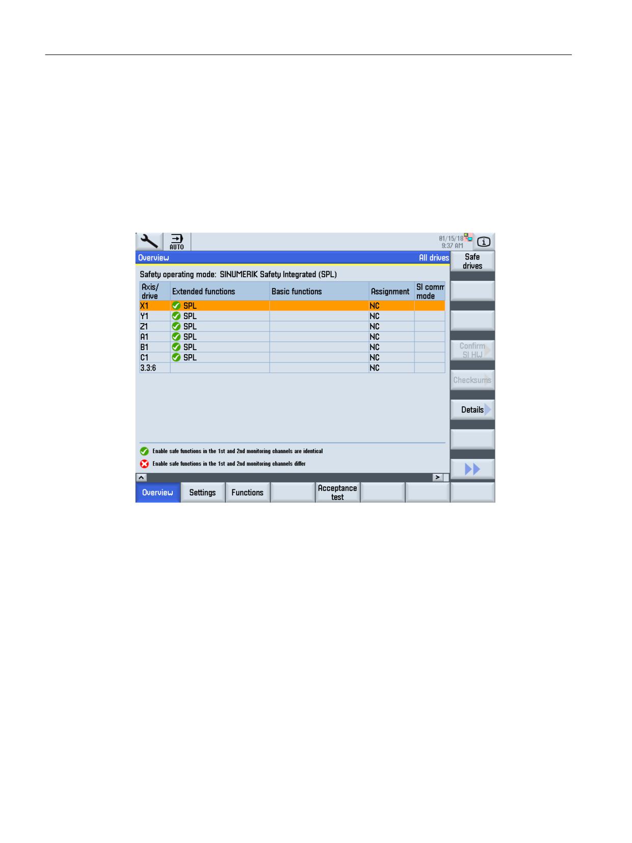
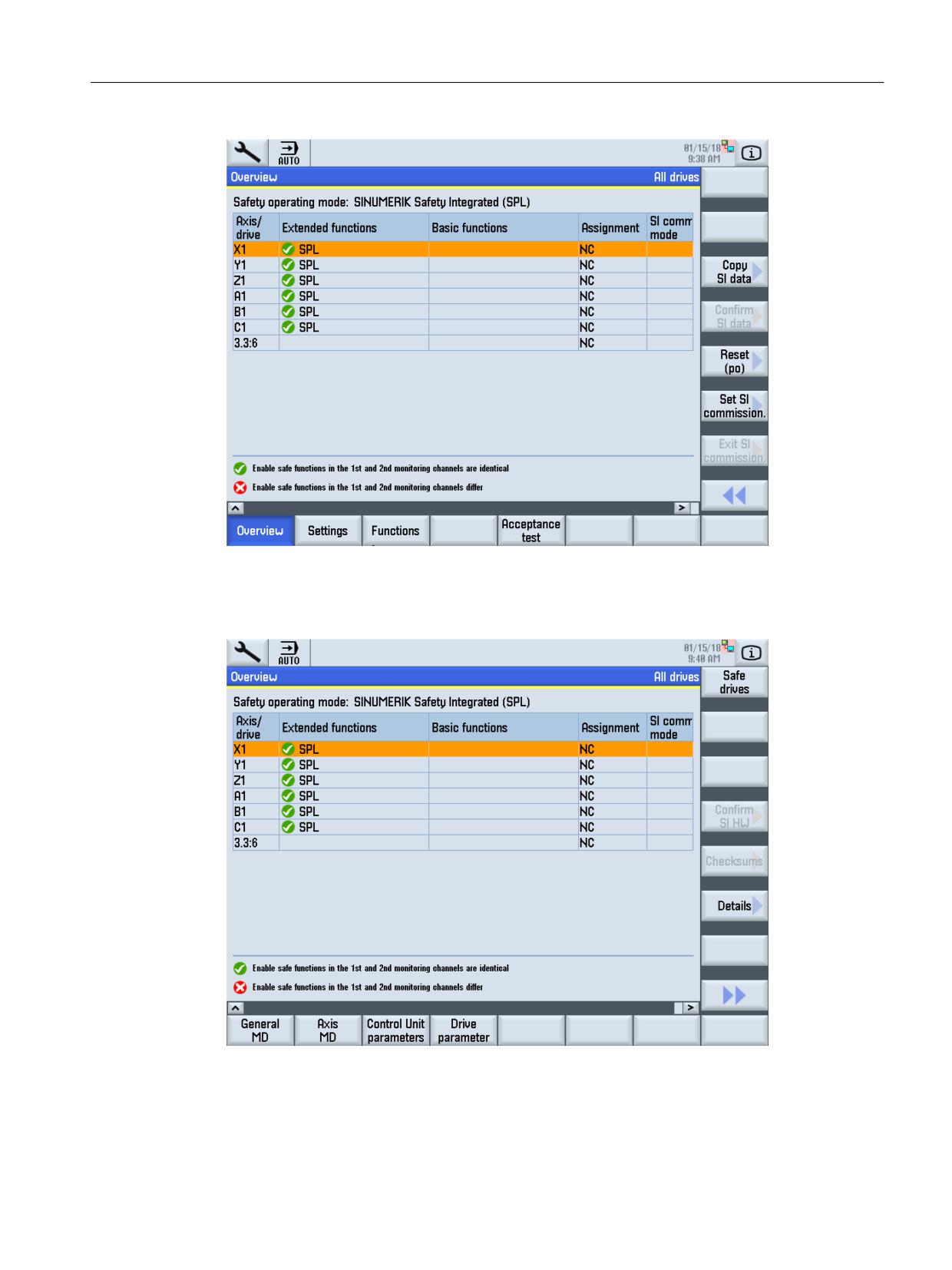
By pressing the "Safety" softkey, you go to the first overview screen "Safety operating mode:
SINUMERIK Safety Integrated (SPL)".
Figure 10-1
Overview: Safety operating mode: SINUMERIK Safety INTEGRATED (SPL)
A new vertical softkey bar is opened using softkey ">>" (overview 2).
Safety Integrated (system-integrated)
518
Function Manual, 10/2020, 6FC5397-4BP40-6BA2
Commissioning
10.2 Images of the user interface and softkeys
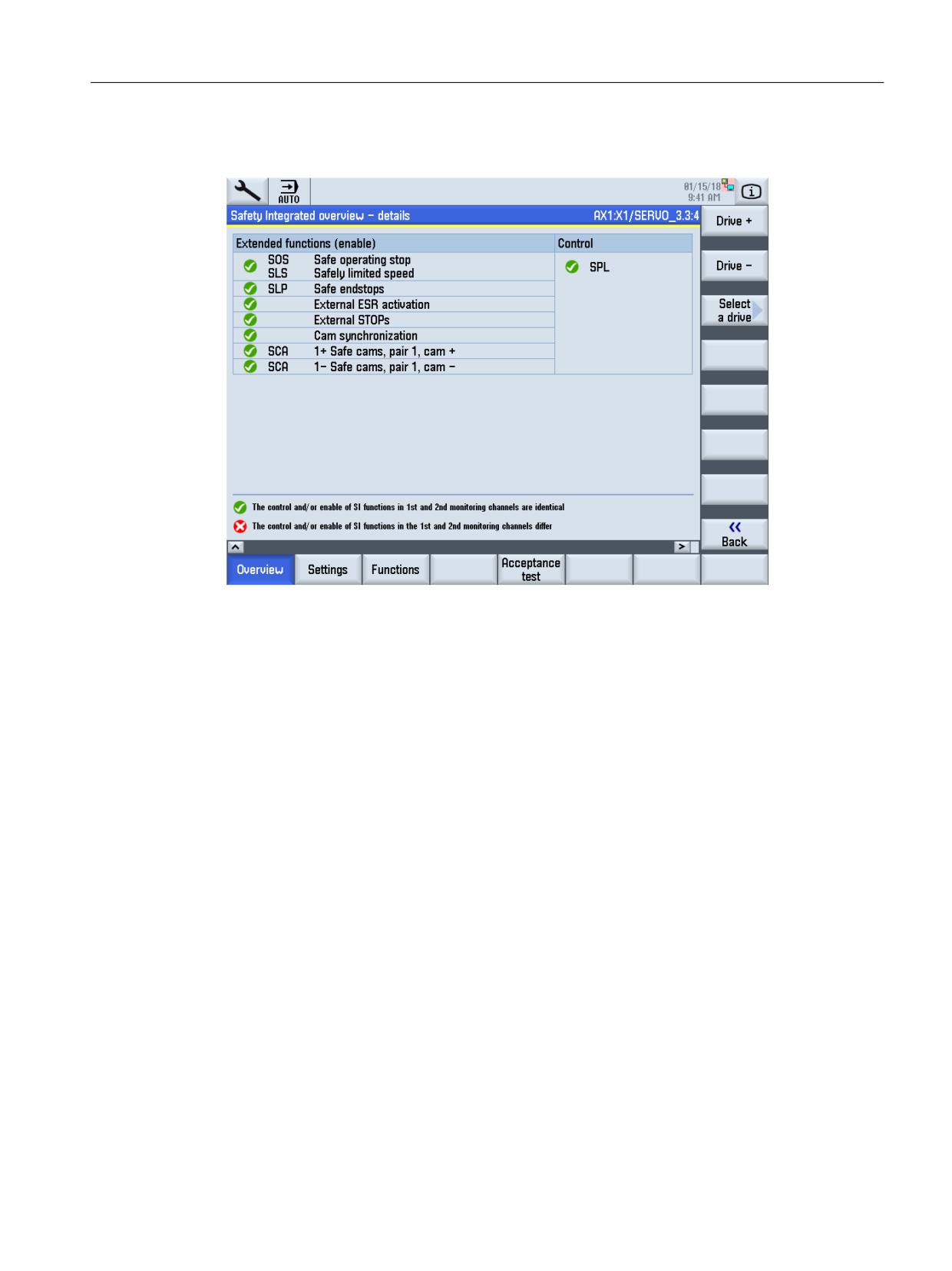
Figure 10-2
Overview: Safety operating mode: SINUMERIK Safety Integrated (SPL)
You can go to the extended horizontal softkey bar by pressing softkey "<<" and the menu
advance key ">" (overview 3).
Figure 10-3
Overview: Safety operating mode: SINUMERIK Safety Integrated (SPL)
Safety Integrated (system-integrated)
Function Manual, 10/2020, 6FC5397-4BP40-6BA2
519
Commissioning
10.2 Images of the user interface and softkeys
The most important information about the active functions is displayed in the "Overview"
window:
• Axis/drive
All NC axes and drives in the system are displayed.
• Extended functions
This column displays whether and if yes, which extended functions are used for this axis or
this drive.
• Basic functions
This column displays as to whether a basic function is used for this axis or for this drive and
its associated control.
• Assignment
NC axis or internal Control Unit of the drive - or a drive object exists on the Control Unit, to
which an NC axis is assigned.
• Setting SI commissioning
Indicates whether the commissioning mode is active for the drive.
• Status symbols
The parameters are evaluated through two channels. The status symbols indicate as to
whether the parameters are identical in both channels.
Green: Parameterization in the 1st and 2nd monitoring channels identical
Red: Parameterization in the 1st and 2nd monitoring channel different
You can supplement or switch over the display in the "Overview" window:
• Using the "Safe drives" softkey, you can toggle between the displays of "All drives" and "Safe
drives".
• Using the "Confirm SI HW" softkey, you can confirm that hardware components have been
replaced after safety commissioning has been completed.
• You can change to the detailed view using the "Details" softkey.
Safety Integrated (system-integrated)
520
Function Manual, 10/2020, 6FC5397-4BP40-6BA2
Commissioning
10.2 Images of the user interface and softkeys
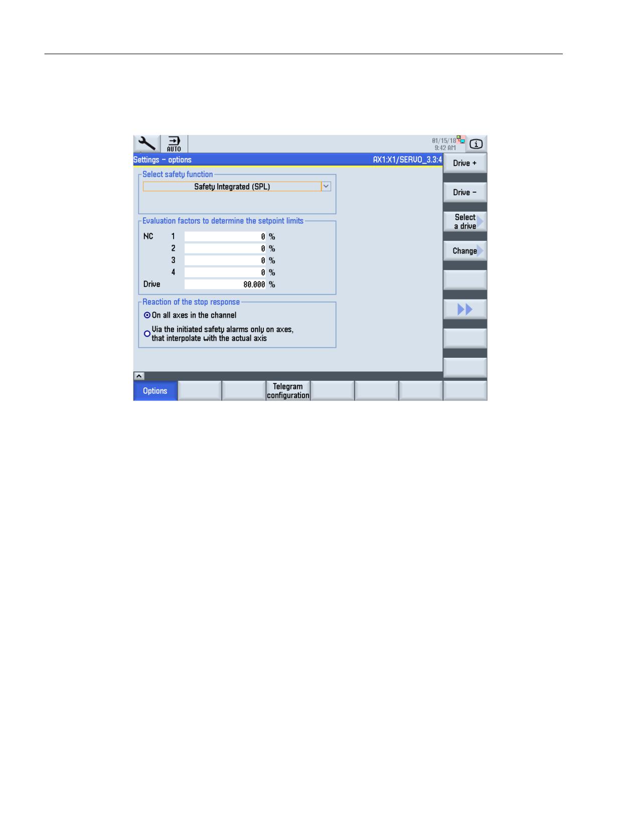
Details
Figure 10-4
Detail view
The most important detailed information about the active safety functions is displayed in the
"Overview - Details" window:
• Extended Functions:
For Extended Functions, the settings from parameter p9501 are evaluated and displayed for
enabled functions.
• Basic functions:
For the basic functions, the settings from parameters p9601, p9602, p9652 are evaluated
and displayed if the function has been enabled.
• Status symbols
The parameters are evaluated through two channels. The status symbols indicate as to
whether the parameters are identical in both channels.
Green: Parameterization in the 1st and 2nd monitoring channels identical
Red: Parameterization in the 1st and 2nd monitoring channel different
• Control:
The control of the particular safety function is displayed in the right-hand column.
Safety Integrated (system-integrated)
Function Manual, 10/2020, 6FC5397-4BP40-6BA2
521
Commissioning
10.2 Images of the user interface and softkeys
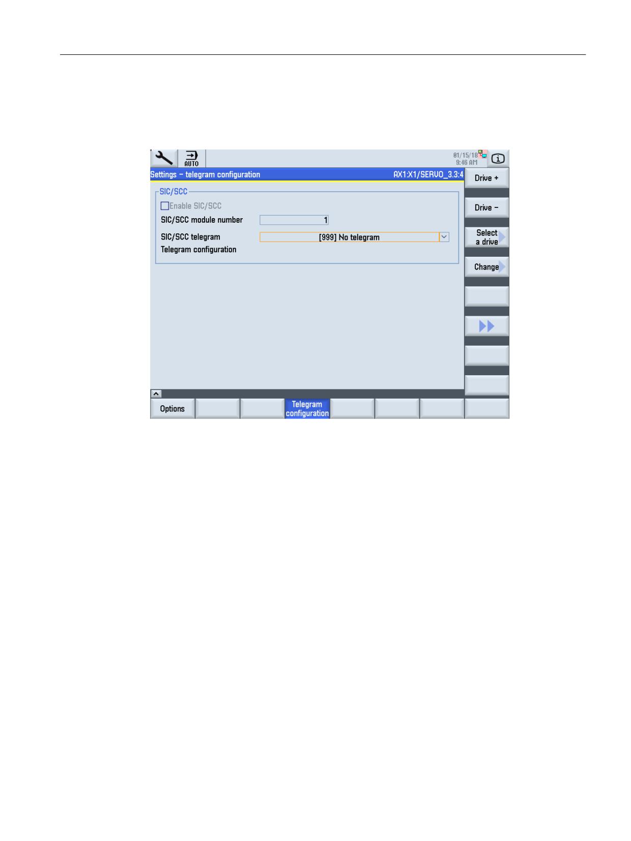
Settings
You can select the safety functions by pressing softkey "Settings" (Fig. 9-2).
Figure 10-5
Settings - options
• In the "Settings - Options" window you can select and enable the safety functions.
• The "Evaluation factors to determine the setpoint limits" can only be activated when an
extended safety function has been set. This option can also be defined if the commissioning
mode is not active.
You can directly enter the evaluation factors as a percentage in the input fields.
Alternatively, you can go to a subsequent dialog by pressing the "Recommended values"
softkey. Here, the axis machine data is always preassigned 80 % - and the drive parameters
100 %. You can accept these recommended values by pressing the "Yes" softkey. You can exit
the dialog with "No" without accepting the values.
• Reaction of the stop response
For NC axes you can define the reaction of the stop response here.
Safety Integrated (system-integrated)
522
Function Manual, 10/2020, 6FC5397-4BP40-6BA2
Commissioning
10.2 Images of the user interface and softkeys
Telegram configuration
The screen to configure the telegram is displayed by pressing the "Telegram configuration"
softkey:
Figure 10-6
Settings - telegram configuration
You can make the following settings in the "Settings - Telegram configuration" window:
• Enable SIC/SCC
Only for Basic Functions and Extended Functions. The following options can be configured:
- SIC/SCC module number
Activates the enable and sets the SIC/SCC module number
- Telegram configuration (p60122)
Sets the telegram for Safety Information Channel (SIC) / Safety Control Channel (SCC). In
this case, telegram 701 is selected.
When required, each setting in this dialog window can be made using a parameter list.
The ">>" softkey is pressed again and the settings saved.
Functions
A Safety Integrated function can be selected by pressing the "Functions" softkey (see Fig. 9-1 ):
• "SI enc. matching" softkey
• "SI-SBR tolerance" softkey
• "SBH/SG" softkey
• "SE safe endstops" softkey
• "SN safe cams" softkey
Safety Integrated (system-integrated)
Function Manual, 10/2020, 6FC5397-4BP40-6BA2
523
Commissioning
10.2 Images of the user interface and softkeys
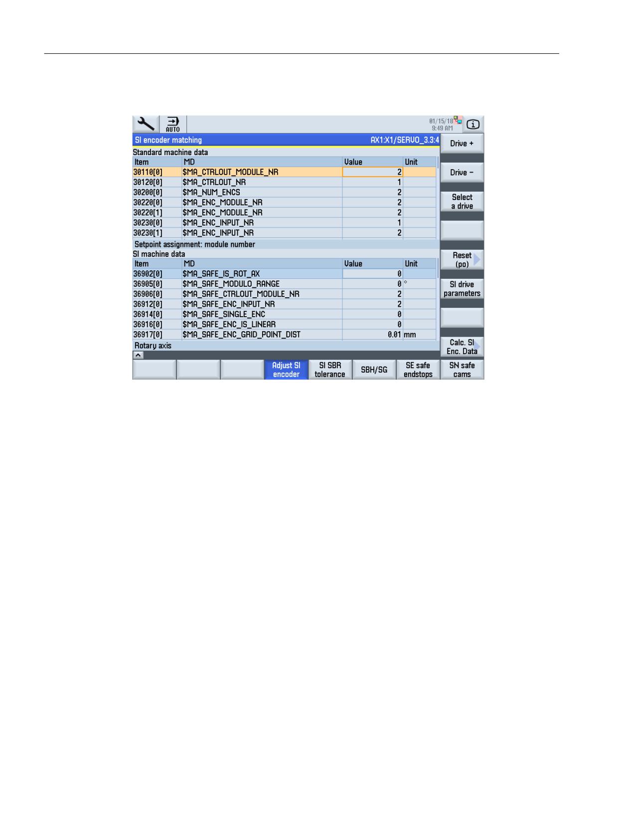
Adapting SI encoders
Figure 10-7
Adapting SI encoders
A list is created comparing the actual values of the relevant MD and Safety MD. The
corresponding drive parameter can be selected using the "SI drive parameters" softkey.
Using the "Calculate SI encoder data" softkey, a parameterizing recommendation for the safety
MD and parameters is determined and displayed. Further, a list that shows the actual values of
the corresponding machine data is created.
When configuring two encoders, the following rules apply:
• The first encoder is always the encoder for the drive
• The second encoder is always the encoder for the NCK
• $MA_ENC_INPUT_NR[0]=1
• $MA_ENC_INPUT_NR[1]=2
Safety Integrated (system-integrated)
524
Function Manual, 10/2020, 6FC5397-4BP40-6BA2
Commissioning
10.2 Images of the user interface and softkeys
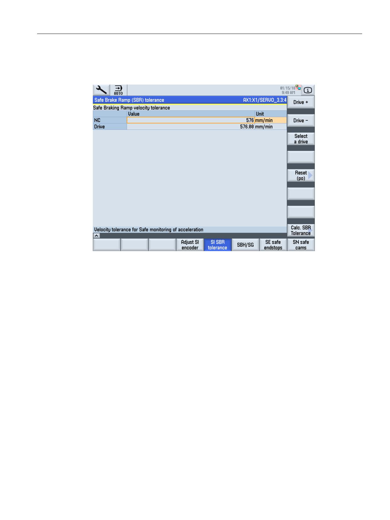
SI-SBR tolerance
The following display appears when pressing the "SI-SBR tolerance" softkey:
Figure 10-8
Safe Acceleration Monitor
You can scroll between the Safety Integrated drives using the "Drive +" and "Drive -" softkeys.
The softkey "Calculate SBR tol." leads to the window where a decision can be made whether the
calculation of the tolerance of the Safe Acceleration Monitor can be agreed ("Accept" softkey) or
the operation is cancelled ("Abort" softkey). Also here, the user can adapt the recommendation.
The settings must be saved using the softkey "Confirm SI data".
To calculate the SBR tolerance, the equations from Chapter "Safe Acceleration Monitor
(Page 133)" are used as basis. A tolerance of 20% is added to the value determined in this fashion.
With the "Accept" softkey, the calculated value for the Safe Acceleration Monitor is accepted in
machine data 36948 $MA_SAFE_STOP_VELO_TOL and parameter p9548 SI Motion SBR
accepted.
Safety Integrated (system-integrated)
Function Manual, 10/2020, 6FC5397-4BP40-6BA2
525
Commissioning
10.2 Images of the user interface and softkeys
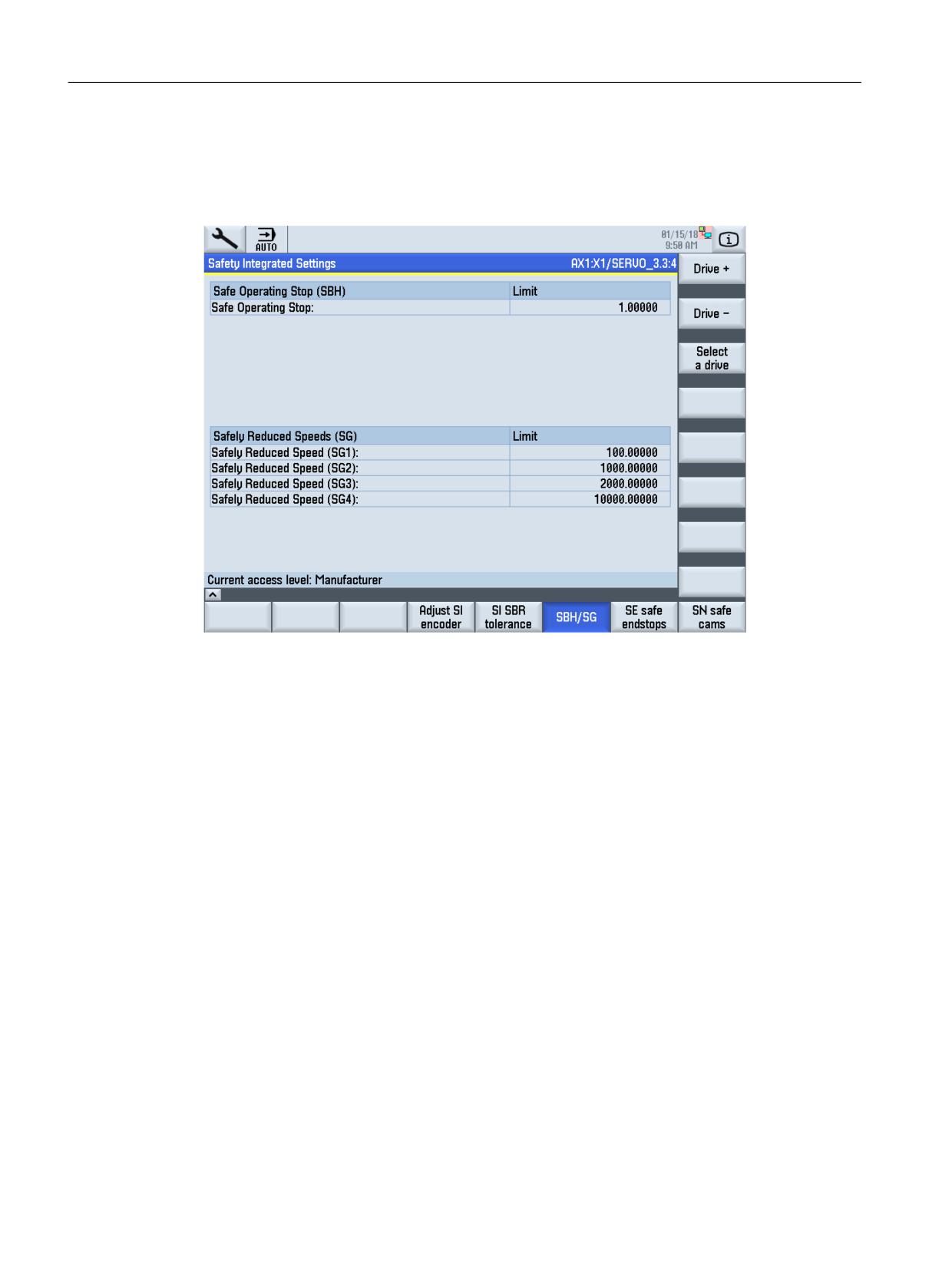
SBH/SG
The configured limits for Safe Operating Stop and Safely-Limited Speed are displayed using the
"SBH/SG" softkey.
Figure 10-9
SBH/SG
You can scroll through the SI drives using the "Drive +" and "Drive -" softkeys.
Safety Integrated (system-integrated)
526
Function Manual, 10/2020, 6FC5397-4BP40-6BA2
Commissioning
10.2 Images of the user interface and softkeys
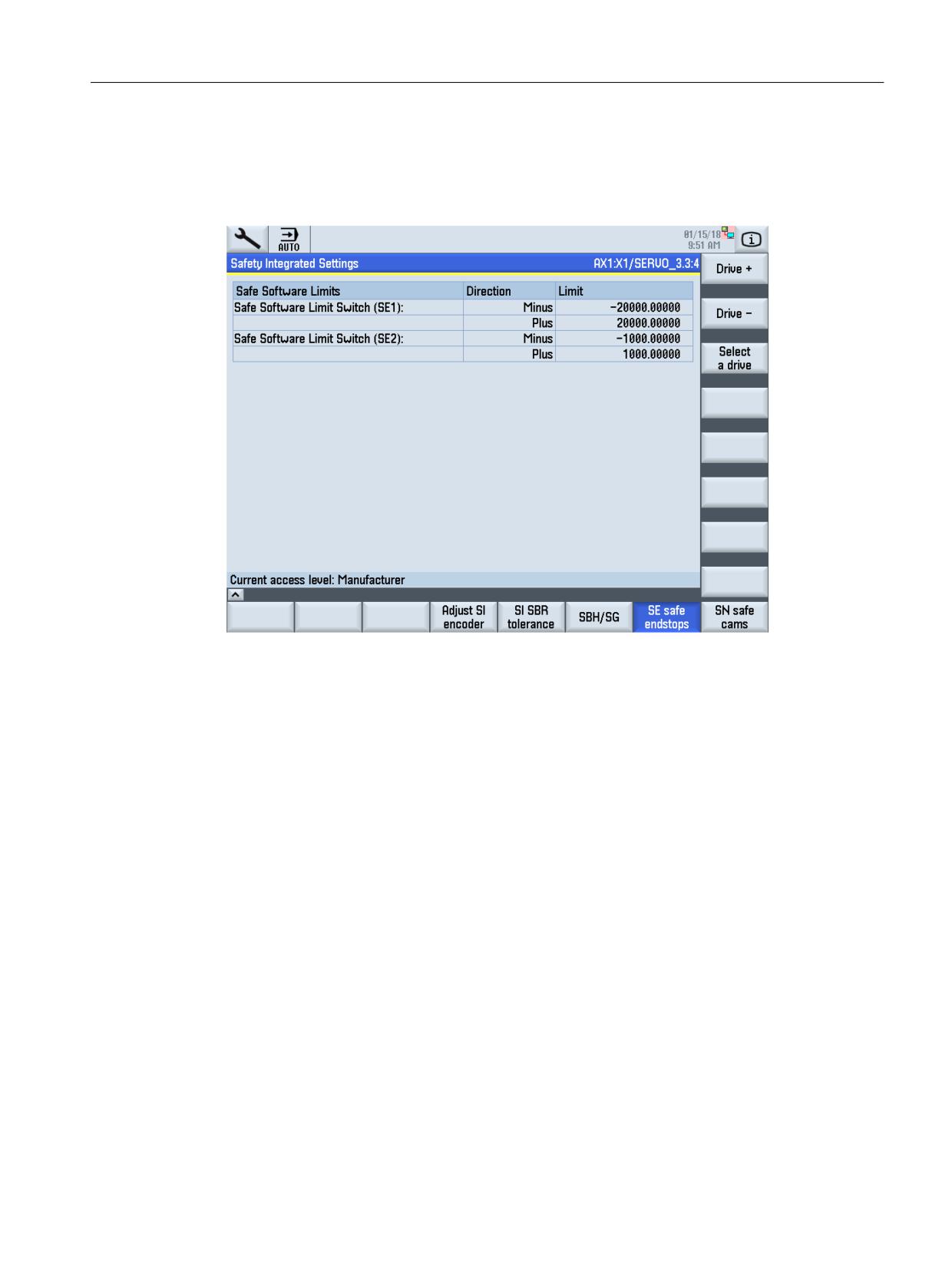
Safe limit positions (SE)
By pressing the "SE safe limit positions" softkey, the configured directions and limits of the safe
limit positions are displayed:
Figure 10-10
Safe software limit positions
Safety Integrated (system-integrated)
Function Manual, 10/2020, 6FC5397-4BP40-6BA2
527
Commissioning
10.2 Images of the user interface and softkeys
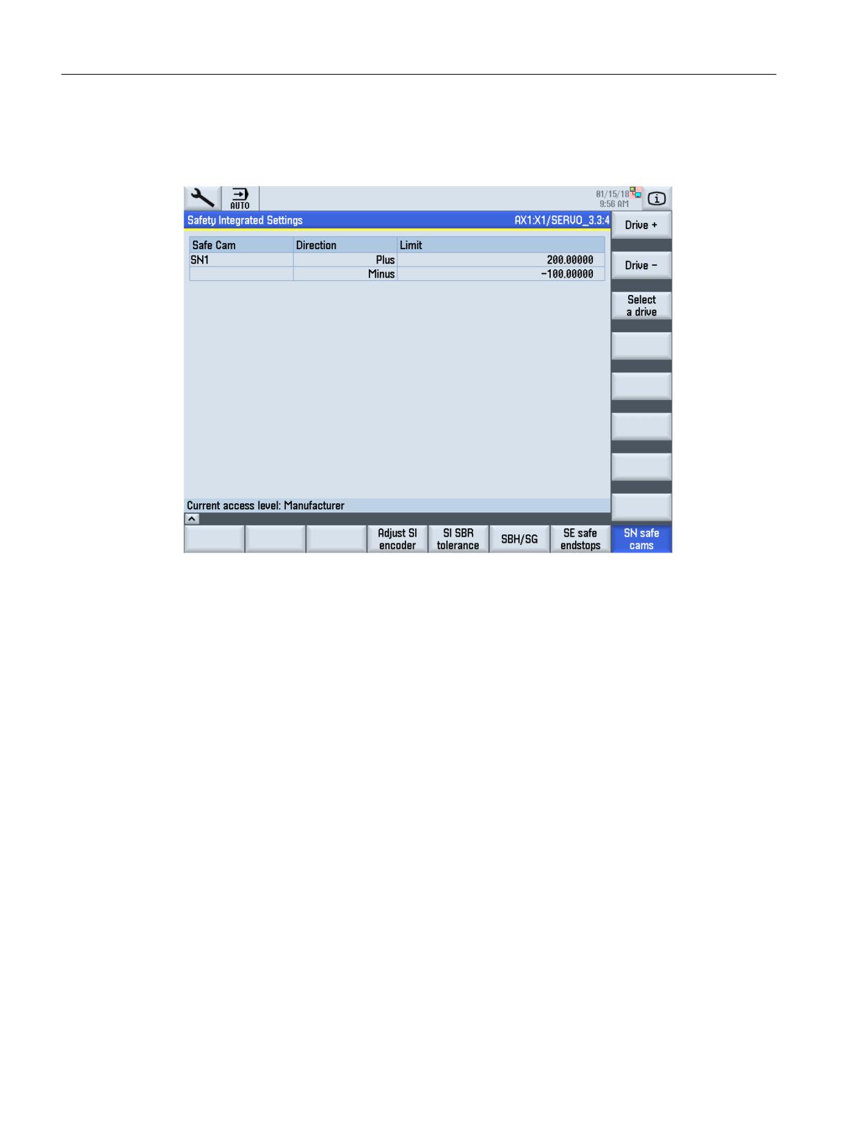
Safe Cams (SN)
With softkey "SN safe cams" the positions and assignments of the Safe Cams are displayed:
Figure 10-11
Safe software cams
SBC
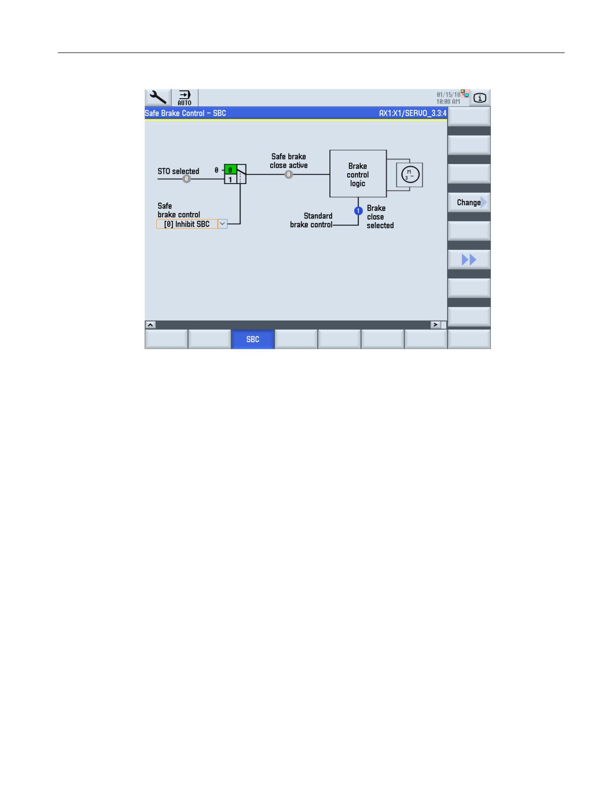
The "Safe Brake Control" function (SBC) is used to safely control holding brakes that function
according to the closed-circuit principle (e.g. motor holding brake).
The "SBC" softkey is reached by pressing the menu advance key. A wiring schematic for the Safe
Brake Control is displayed.
Safety Integrated (system-integrated)
528
Function Manual, 10/2020, 6FC5397-4BP40-6BA2
Commissioning
10.3 Procedure when commissioning the drive for the first time
Figure 10-12
Safe Brake Control
The Safe Brake Control can be enabled or inhibited using this selection list. This selection is
deactivated if a motor holding brake is not included in the configuration (p1215).
See also
Procedure when commissioning the drive for the first time (Page 529)
10.3
Procedure when commissioning the drive for the first time
This Chapter describes the steps that are necessary to commission the safety functions
integrated in the system. The drive-integrated safety function "Safe Operating Stop" (SH) is also
used for the safety functions integrated in the system. As a consequence, a minimum
configuration of the drive-based safety function is required. The SH function itself does not have
to be enabled, but possibly a required brake control (SBC) must be parameterized.
Commissioning SH/SBC/SS1 via the terminal control is described in detail in Chapter "Safety
Functions integrated in the drive (Page 51)".
It is advisable to commission the machine so that at least the axes can be moved. The safety
monitoring functions can then be immediately tested after SI data has been entered. This type
of test is absolutely essential in order to detect any data entry errors.
The following steps must be taken in the specified sequence for commissioning:
Safety Integrated (system-integrated)
Function Manual, 10/2020, 6FC5397-4BP40-6BA2
529

Commissioning
10.3 Procedure when commissioning the drive for the first time
Note
If only the SH, SBC and SS1 functions are used, then commissioning is carried out as described
in Chapter “Commissioning the STO, SBC and SS1 functions (Page 70)”.
WARNING
Firmware versions
From SINAMICS SW2.5 and higher, the following applies:
In a system configuration, the firmware versions of the DRIVE-CLiQ components can only differ
from the versions on the CF card, if either
a) The automatic upgrade/downgrade (parameter p7826) is deactivated, or
b) components with a new firmware version can no longer be downgraded to the status of the
version available on the CF card.
Case a) is not permitted when Safety Integrated is used. The automatic upgrade/downgrade
must never be disabled when Safety Integrated is used. (automatic firmware update (p7826)
must be equal to 1)
Case b) is only permissible if this combination has been explicitly approved by the
manufacturer.
Step 1:
Enable option
• Starting screen "Commissioning/NC/Safety-Integrated": Set the password (at least the
machine manufacturer password)
• "General machine data" screen:
Set the options
Step 2:
• Commissioning PROFIsafe (see Chapter "Parameterizing the PROFIsafe communication
(NCK) (Page 192)") and the associated PROFIsafe I/O.
• Commissioning safety-related CPU-CPU communication (F_DP communication) (see
Chapter "Configuring and parameterizing the F_DP communication (Page 215)").
• Commissioning the safety programmable logic (see Chapter "Starting the SPL (Page 261)")
Step 3:
In the screen "Axis-specific machine data", set the function enable bits (MD36901
$MA_SAFE_FUNCTION_ENABLE and MD 36902 $MA_SAFE_IS_ROT_AX) of all axes for which the
safety-related motion monitoring functions are to be used. Alternatively, the machine
manufacturer can completely commission the axis-specific safety functions axis-for-axis.
Safety Integrated (system-integrated)
530
Function Manual, 10/2020, 6FC5397-4BP40-6BA2
Commissioning
10.3 Procedure when commissioning the drive for the first time
Entering and checking the monitoring clock cycle.
• "General machine data" screen:
Enter the factor for the monitoring clock cycle in the data
$MN_SAFETY_SYSCLOCK_TIME_RATIO (see Chapter "Monitoring cycle (Page 81)" and
Chapter " Crosswise data comparison (CDC) (Page 81)").
• The actual monitoring time is directly displayed in data $MN_INFO_SAFETY_CYCLE_TIME.
Note
Before the next NCK RESET is initiated, you must copy the actual monitoring clock cycle to
parameter p9500 "SI Motion monitoring clock cycle" of the drive using softkey "Copy SI data" in
the "Drive configuration" screen.
Note regarding the axis assignment
Note
The drives must be assigned to the axis due to the degrees of freedom that exist for the
PROFIdrive telegram configuring - also in the SI machine data.
This is the reason that the recommendations when configuring the drive configuration also
apply when configuring Safety Integrated:
• Using the standard configuration and the recommended logical basis addresses in STEP7.
• No re-parameterization of the selected list of drive objects in drive parameter p0978.
Under these prerequisites, the following cases can occur:
a) If the drive assignment was left at the standard value via machine data MD30110
$MA_CTRLOUT_MODULE_NR, MD30220 $MA_ENC_MODULE_NR[0/1] and MD13050
$MN_DRIVE_LOGIC_ADDRESS, then also the drive assignment in MD36906
$MA_SAFE_CTRLOUT_MODULE_NR and MD10393 $MN_SAFE_DRIVE_LOGIC_ADDRESS must
not be changed.
b) If the drive assignment was changed using the machine data MD30110:
$MA_CTRLOUT_MODULE_NR and MD3022: $MA_ENC_MODULE_NR[0/1], then MD36906:
$MA_SAFE_CTRLOUT_MODULE_NR should be parameterized to the same value as for
MD30110: $MA_CTRLOUT_MODULE_NR
c) If the drive assignment was made by interchanging the logical drive addresses in MD13050:
$MN_DRIVE_LOGIC_ADDRESS, then the same marshalling should also be made in MD10393:
$MN_SAFE_DRIVE_LOGIC_ADDRESS.
Example: Drives 1 and 2 were exchanged by interchanging MD13050, index 0 and 1.
MD13050[0] was parameterized to 4140 and MD 13050[1] was parameterized to 4100. Then,
indices 0 and 1 of MD10393 must also be interchanged, i.e. 10393[0] must be set to 6724 and
MD10393[1] must be set to 6700.
The user is provided with support when assigning axes under the HMI path "Commissioning/
Drive system/Drive units/PROFIBUS connection".
Safety Integrated (system-integrated)
Function Manual, 10/2020, 6FC5397-4BP40-6BA2
531
Commissioning
10.3 Procedure when commissioning the drive for the first time
Step 4:
Commissioning the drive-based SH/SBC/SS1 functions.
Note
The parameters of the safety functions integrated in the drive have their own password
protection that is however de-activated before commissioning.
In the SINUMERIK environment we recommend that this password protection is not activated as
the complete commissioning area is password protected.
The procedure to change the SI password is described in Chapter "Sequence when
commissioning STO, SBC and SS1 (Page 71)"
• In the drive, the SI commissioning mode must be selected. If an attempt is made to change
the drive-based SI parameters without being in the commissioning mode, then the drive
rejects this with a message. A prerequisite for the commissioning mode is that the pulses
have been cancelled for all of the drives. For all drives, the commissioning mode is selected
using the "Activate drive commissioning" softkey in the "Safety Integrated" screen. When
pressing this softkey, from the HMI, 95 is written into every drive parameter p0010, if:
- In the associated NC axis, MD36901 $MA_SAFE_FUNCTION_ENABLE has a value not
equal to 0, or
- There is a value not equal to 0 in drive parameter p9501 "SI enable safety-related
functions".
• Using the "Activate drive commissioning" softkey, the user can also pre-assign the PROFIsafe
addresses using parameter p9810 SI PROFIsafe address (Motor Module).
• Parameterize the drive-based functions in the "Drive machine data" screen. These especially
include:
- Function enable SBC (p9602/p9802)
- Forced checking procedure timer p9659 = 9000 when using Safety Sinumerik, and
possibly
- PROFIsafe address, if it hasn't already been set using the "Activate drive commissioning"
softkey
- CRC using the parameters of the SI functions integrated in the drive (this is also realized
using the "Deactivate drive commissioning" softkey, see the next point)
• Setting the CRC and saving the parameterization that was just made is carried-out using the
"Deactivate drive commissioning" softkey.
Step 5:
Set the monitoring function for all of the axes to be safely monitored.
Enter the following one after the other in the "Axis-specific machine data" screen:
1. Axis characteristics (rotary or linear axis)
2. Measuring-circuit assignment, i.e. which encoder will supply the safety actual value, what
are the characteristics of this encoder and how it is mechanically mounted.
Safety Integrated (system-integrated)
532
Function Manual, 10/2020, 6FC5397-4BP40-6BA2
Commissioning
10.3 Procedure when commissioning the drive for the first time
3. Monitoring limit values and tolerances
4. Changeover and monitoring times
5. Stop responses after a monitoring function has responded
6. Assignment of safety-relevant inputs and outputs, i.e. which sources are supplying the
control signals for the NC monitoring channel , and where do the feedback signals go (for the
drive monitoring channel, this logical assignment must be programmed in the PLC, i.e. there
are no corresponding drive parameters).
Step 6:
Set the monitoring and save the data for all of the associated drives. Here, almost all data entered
under Step 6 are again entered in the "Drive machine data" screen. When the softkey "Copy SI
data" in the "Safety Integrated" screen is pressed, the settings from Step 5 are automatically
entered, with the exception of Points 2 and 6. Point 2 cannot be copied because the drive always
operates with the motor encoder and for a two-encoder system, has other characteristic data
than the encoder evaluated from the NC. The 6th point is not applicable on the drive side. The
following operating steps are therefore involved:
1. Press the softkey "Copy SI data" in the screen "Safety Integrated".
2. For each drive, enter the encoder configuration using the softkey "Adapt SI encoder". At the
same time, the data, copied under Point 1 in Step 6 can be subject to a visual check.
3. Initiate an NCK and drive reset using the appropriate softkey. In this case, component IDs are
also transferred from the drive to the NCK.
4. Press the softkey "Acknowledge SI data" in the "Drive configuration" screen. A dialog box
describing the function of the softkey then appears: After acknowledging with "OK", the
actual checksum of the safety-related data is then saved in both monitoring channels and
monitored for changes from this point onwards. Further, drive data is automatically saved in
a non-volatile fashion.
5. A dialog box is displayed on the screen requesting you to perform an acceptance test. This
dialog must be acknowledged. Now carry out the NCK reset and drive reset that are listed.
6. Activate SPL protection.
Step 7:
Issue a user agreement (see Chapter "User agreement (Page 92)")
• The safe limit positions and Safe Cams are now activated (provided that they have been
enabled, see Chapter "Enabling the safety-related functions (Page 98)"). This step can be
omitted if you do not wish to use either of these functions.
• The key-operated switch must be set to position 3 in order to issue a user agreement.
Safety Integrated (system-integrated)
Function Manual, 10/2020, 6FC5397-4BP40-6BA2
533
Commissioning
10.4 Series commissioning
Step 8:
Carry out the acceptance test and enter in the logbook.
• All of the safety functions that have been enabled must be tested. For suggestions on how
to test and check activated SI functions, please refer to Chapter "User agreement (Page 92)".
• The parameterization of all PROFIsafe I/O components should be checked using a function
test and checking the printout of the hardware configuration from SIMATIC Step 7.
Step 9:
• Save all machine data using the "Services" area. This data can be used to commission series
equipment.
• Save (back-up) the complete SIMATIC Step7 project.
WARNING
Old MD files
After the acceptance test has been completed, all illegal (old) MD files must be removed from
the Flashcard (to avoid confusion between old and new data). Data that corresponds to the
acceptance test data must be backed-up (archived).
Step 10:
Delete (clear) the password in order to prevent the unauthorized change of machine data.
See also
Acceptance test (Page 537)
10.4
Series commissioning
The setting for the safety monitoring functions is automatically transferred with other data in
the course of a normal series commissioning process. The following steps need to be taken in
addition to the normal commissioning procedure:
1. Enter a user agreement
2. Carry out the acceptance test
Sequence of operations for series commissioning
The following sequence of operations is recommended when commissioning series equipment:
• Download the data set for the series machine into the control.
• Adjust the absolute encoder.
Safety Integrated (system-integrated)
534
Function Manual, 10/2020, 6FC5397-4BP40-6BA2

Commissioning
10.5 Changing machine data
• Carry out a POWER ON.
This ensures that any errors - i.e. deviations in the data content that may exist between the
NCK and drive - will be detected by the checksum check and crosswise data comparison.
Data must be checked if an error is detected. Cross check errors on the hardware-related cross
checksums (Alarm 27035, message F01680 with ID 2) or Alarm 27032 are normal if the
series commissioning data come from another machine. These errors can be resolved using
the "Confirm SI-HW" softkey (see Chapter "Replacing a motor or encoder (Page 551)").
If an error no longer occurs, then data has not been changed and is identical to the
acceptance test data. The copy function may be used if data is subsequently altered.
• Carry out random function tests.
The tests are required for acceptance of the new machine.
Software/hardware upgrade
WARNING
Upgrading software
Please carefully read the instructions in the relevant Update Manual before updating the
software.
WARNING
Firmware versions
In a system configuration, the firmware versions of the DRIVE-CLiQ components can only differ
from the versions on the CF card, if either
a) The automatic upgrade/downgrade (parameter p7826) is deactivated, or
b) components with a new firmware version can no longer be downgraded to the status of the
version available on the CF card.
Case a) is not permitted when Safety Integrated is used. The automatic upgrade/downgrade
must never be disabled when Safety Integrated is used. (automatic firmware update (p7826)
must be equal to 1)
Case b) is only permissible if this combination has been explicitly approved by the
manufacturer.
10.5
Changing machine data
The user must enter the correct password before he can change the machine data for SI
functions to the system. After data for SI functions has been altered, a new acceptance test must
be carried out on the SI function involved and then recorded and confirmed in the acceptance
report.
Change log
Changes made to NCK machine data important for Safety Integrated are recorded in a display
data. The time that the change is made is displayed in
Safety Integrated (system-integrated)
Function Manual, 10/2020, 6FC5397-4BP40-6BA2
535
Commissioning
10.5 Changing machine data
an axis 36996 $MA_SAFE_CONFIG_CHANGE_DATE[0...6] and
an NCK-MD13316 $MN_SAFE_GLOB_CFG_CHANGE_DATE[0...6].
This MD can neither be overwritten by manual entry nor by loading an MD archive. The only way
to delete this MD is to boot the control from the general reset mode (service switch position 1).
This data is updated when the following changes are made to the NCK machine data:
• A modified safety MD configuration is activated
(NCK Safety MD have been changed and acknowledged by correction of
$MA_SAFE_DES_CHECKSUM or $MN_SAFE_GLOB_DES_CHECKSUM). Changes, depending
on the modified MD context (axis-specific MD or NCK-MD), are listed in MD
$MN_SAFE_GLOB_CONFIG_CHANGE_DATE or in MD $MA_SAFE_CONFIG_CHANGE_DATE.
• Changes in the S7 configuration regarding PROFIsafe-relevant parameters. These are all of
the values that go into the PROFIsafe CRC1 (e.g. PROFIsafe source and target address,
PROFIsafe monitoring time). Changes are listed in MD
$MN_SAFE_GLOB_CONFIG_CHANGE_DATE.
• When MD $MA_SAFE_FUNCTION_ENABLE is changed from values not equal to zero to zero,
or from zero to values not equal to zero. These changes mean that the safety functionality of
an axis is completely enabled/disabled. Changes are listed in MD
$MN_SAFE_CONFIG_CHANGE_DATE.
Other changes to MD $MA_SAFE_FUNCTION_ENABLE (selecting/deselecting individual
safety functions) always change MD $MA_SAFE_ACT_CHECKSUM, which themselves have to
be acknowledged by changes to MD $MA_SAFE_DES_CHECKSUM. Changes are listed in MD
$MA_SAFE_CONFIG_CHANGE_DATE.
• When MD $MA_SAFE_FUNCTION_ENABLE is changed by reducing the safety option. If the
scope of axis-specific safety functions is enabled for more axes than are set in the safety
option data, the function enable for the excess number of axes is automatically cancelled
again when the control boots.
This deletion is noted in MD $MA_SAFE_CONFIG_CHANGE_DATE. Further, the operation is
associated with the initiation of Alarm 8041 “Axis %1: MD %2 reset, the associated option is
not sufficient". This alarm disappears at the next power on, however the entry in MD
$MA_SAFE_CONFIG_CHANGE_DATE is kept.
• Loading an MD archive that is different to the currently active NCK-MD block.
• When upgrading (corresponds to downloading an MD archive)
• Series commissioning (corresponds to downloading an MD archive)
Supplementary conditions
Changes to the MD configuration are only noted/documented when the change becomes active,
i.e. after altering MD $MA_SAFE_DES_CHECKSUM / $MN_SAFE_GLOB_DES_CHECKSUM and a
subsequent power on.
When a commissioning archive is downloaded, then in a first step, a change is noted in the
change history. If the currently active safety configuration is saved in this commissioning archive
(⇒ effectively no change to the safety configuration), then the change that was previously
entered is withdrawn. This is realized by copying the data
$MA_SAFE_CONFIG_CHANGE_DATE[1] to [0], [2] to [1], [3] to [2], [4] to [3], [5] to [4], [6] to [5].
Is entered into $MA_SAFE_CONFIG_CHANGE_DATE[6] as date "00/00/0000 00:00:00". The
same is true for the entries in MD $MN_SAFE_GLOB_CONFIG_CHANGE_DATE.
Safety Integrated (system-integrated)
536
Function Manual, 10/2020, 6FC5397-4BP40-6BA2

Commissioning
10.6 Acceptance test
10.6
Acceptance test
10.6.1
General
Requirements for acceptance tests are derived from the EU Machinery Directive. Accordingly,
the machine manufacturer (OEM) is responsible for the following:
• to carry out an acceptance test for safety-related functions and machine parts, and
• Issue an "Acceptance certificate" that includes the results of the test.
When using the Safety Integrated function, the acceptance test is used to check the correct
configuring of the SI monitoring functions used in the NCK, PLC and drive. The test objective is
to verify the correct implementation of the defined safety functions, to check the implemented
test mechanisms (forced checking procedure measures) and to examine the response of
individual monitoring functions by explicitly violating tolerance limits. This should be carried out
for all safety functions, i.e. for the axis-specific monitoring functions, the SPL, the safety-related
communication relationships, the safety-related I/O etc.
WARNING
Acceptance test
The acceptance test is used to check that the safety functions have been correctly
parameterized. Using the acceptance test, potential configuring errors are to be identified and
the correct configuring documented.
The measured values (e.g. distance, time) and the system behavior determined (e.g. initiating
a specific stop) when carrying out the acceptance test are used to check the plausibility of the
configured safety functions. The recorded measured values are typical and are not worst-case
values. They represent the behavior of the machine at the time of measurement. The
measurements cannot be used to derive maximum distances for over-travel.
WARNING
Changing machine data
If the machine data for SI functions is changed, a new acceptance test must be performed for
the modified SI function and documented in the acceptance report.
Note
The acceptance test should also be carried out for the PROFIsafe I/O.
Safety Integrated (system-integrated)
Function Manual, 10/2020, 6FC5397-4BP40-6BA2
537
Commissioning
10.6 Acceptance test
Information regarding carrying out the acceptance test
• Some of the standard NC monitoring functions, such as zero speed monitoring, software
limit switches, etc. must be de-activated (monitoring limits must be made less sensitive)
before the acceptance test is carried out.
The function sequences can be acquired and listed using the servo trace function or using the
D/A converter output.
• After the SPL has been commissioned the access authorization for the NCK-SPL (SAFE.SPF) via
the user interface must be reduced to the manufacturer or service level.
• Note the information in Chapter "Procedure when commissioning the drive for the first time
(Page 529)".
• The acceptance report comprises checking the alarm displays and including the alarm
reports in the overall acceptance report. In order to obtain reproducible and comparable
alarm displays, MD10094 $MN_SAFE_ALARM_SUPPRESS_LEVEL must be set to 0 during the
acceptance test in order to avoid suppressing alarm outputs.
• For SINUMERIK 840D sl, to document a test stop that has been carried out, it is sufficient to
just log the test stop alarms of the NCK (27002); it is not absolutely necessary to log the test
stop alarms of the SINAMICS S120 (C01798).
Authorized person, acceptance report
The test of each SI function must be carried out by an authorized person and logged in the
acceptance report. The report must be signed by the person who carried out the acceptance test.
Authorized in this sense refers to a person who has the necessary technical training and
knowledge of the safety functions and is authorized by the machine manufacturer to carry out
the test.
Documentation, data archiving
The results of the acceptance test as well as all hardware and software changes as shown in the
following table should be documented in a suitable form.
In addition to the acceptance report, the following SI relevant data must be archived:
NC machine data
Drive parameters
PLC-/NCK-SPL program
PLC project
Necessity of an acceptance test
A full acceptance test (as described in this Chapter) must always be carried out when the
functionality of Safety Integrated is commissioned for the first time on a machine.
Extended safety-related functionality, transferring the commissioned software to additional
series machines, modifications to the hardware, software upgrades, changes within the scope
of modular machine concepts etc. make it necessary to carry out the acceptance test - possibly
with a reduced test scope.
Safety Integrated (system-integrated)
538
Function Manual, 10/2020, 6FC5397-4BP40-6BA2
Commissioning
10.6 Acceptance test
In order to define a partial acceptance test, it is necessary in the first instance to specify the
acceptance test objects, and in the second instance to define logical groups which represent the
elements of the acceptance test. The assignment of the safety-relevant machine data and
parameters to difference CRCs support this grouping (e.g. to support modular machine
concepts).
Content of the complete acceptance test
1) DOCUMENTATION
Documentation of the machine including the safety functions
1.1
Machine description (with overview diagram)
1.2
Details about the control system
1.3
Configuration diagram
1.4
Function table
Active monitoring functions depending on the operating mode, the protective doors and
other sensors/CPU-CPU communication
Ideally, this table should be the objective and result of the configuring work.
1.5
SI functions per axis
1.6
Information and data about safety equipment
2) FUNCTION TEST PART 1
General function check incl. checking the wiring/programming/configuring
2.1
Test the switch-off signal paths
(check the forced checking procedure of the switch-off signal paths)
2.2
Test the external stops
2.3
Test of the holding torque
2.4
Test the forced checking procedure of the inputs and outputs
2.5
Test the Emergency Stop function and the safety circuits
2.6
Test all SPL switching states and associated input/output signals
(test of the function table)
2.7
Test of the PROFIsafe input/output signals
Recommendation:
A forced checking procedure should be automatically performed each time that the control
system runs up.
3) FUNCTION TEST PART 2
Detailed function test incl. checking the values of the individual SI functions used
3.1
Test of the SI function Safe Operating Stop - SBH
(with evaluated measurement diagram or measured values)
3.2
Test of the SI function safely reduced speed - SG
(with the evaluated measurement diagram or measured values)
3.3
Test of the SI function safety-related output n < nx
(with evaluated measurement diagram or measured values)
3.4
Test the SI function safe limit positions - SE
(with evaluated measurement diagram or measured values)
Safety Integrated (system-integrated)
Function Manual, 10/2020, 6FC5397-4BP40-6BA2
539
Commissioning
10.6 Acceptance test
3.5
Test of the SI function Safe Cams - SN
(check using the diagnostics display or assigned SGAs or with the evaluated measuring
diagrams and measured values)
3.6
If necessary, test the SI function external stops
(with evaluated measurement diagram or measured values)
3.7
Test the SI function SBC/SBT
(with evaluated measurement diagram or measured values / PROFIsafe I/O)
4) Supplementary measures
4.1
Function test, actual value sensing
After replacing a component, the system is switched on and briefly operated in both
directions.
Warning
During this process, all personnel must keep out of the danger area.
With the motion monitoring functions are activated, check that the SI encoder evaluation
and count direction match the encoder evaluation and count direction of SINUMERIK.
4.2
Checking the SGE/SGA signals of the relevant module
4.3
After changing the acceleration behavior/jerk, axis-specific tests are carried out of Func-
tion Test Part 2
4.4
Test the new safety functionality
4.5
Checking checksums and software versions, comparing whether checksums and soft-
ware versions are identical with the reference machine. Hardware checksum 36998[1] is
always different from that of the reference machine.
5) COMPLETING THE REPORT
Documenting and reporting the tested commissioning state
5.1
Check the SI machine data
5.2
Check the hardware configuration of the PROFIsafe I/O
5.3
Check the NCK and SINAMICS software releases
5.4
Log of the checksums (axis MD / SPL / PROFIsafe I/O)
5.5
Completing the NCK commissioning (protect synchronized actions)
5.6
Complete the PLC commissioning
5.7
Verify data archiving
APPENDIX
Reports/measurement plots for FUNCTION TEST PARTS 1/2
• Alarm logs/servo trace measurements (only for a conventional acceptance test)
• Archive the following SI-relevant data:
- NC machine data
- Drive parameters
- PLC-/NCK-SPL program
- PLC project
Safety Integrated (system-integrated)
540
Function Manual, 10/2020, 6FC5397-4BP40-6BA2

Commissioning
10.6 Acceptance test
Note
The template in the toolbox is only a recommendation.
An electronic template for the acceptance report is available:
• in the toolbox for SINUMERIK 840D sl
• on DOConCD for SINUMERIK 840D sl
• on the service CD for SINUMERIK 840D sl
The acceptance report is divided into the following sections:
• Plant/system description
• Description of the safety functions
• Test of safety functions
Effect of the acceptance test for specific measures
Table 10-1
Recommendations for the scope of the acceptance test depending on specific measures
Measure
Documentation
Function test
Function test
Supplementary
Completion of the
measures
report
Part 1
Part 2
Replace the encod-
Inclusion of hard-
No
No
Point 4.1
Document the
er system
ware data
modified check-
sum. From soft-
(see "Replacing a
ware release 4.5
motor or encoder
SP6, the modified
(Page 551)")
checksum is docu-
mented in the log
file.
Replace an SMC,
Inclusion of hard-
No
No
Point 4.1
Document the
SME module
ware data/ soft-
modified check-
ware version data
sum. From soft-
(see "Replacing a
ware release 4.5
motor or encoder
SP6, the modified
(Page 551)")
checksum is docu-
mented in the log
file.
Replacing a motor
Inclusion of hard-
No
No
Point 4.1
Document the
equipped with
ware data/ soft-
modified check-
DRIVE-CLiQ
ware version data
sum. From soft-
ware release 4.5
(see "Replacing a
SP6, the modified
motor or encoder
checksum is docu-
(Page 551)")
mented in the log
file.
Replacing a Motor
Inclusion of hard-
Yes, only Points 2.1
No
Point 4.1
No
Module
ware data/ soft-
and 2.2
ware version data
Safety Integrated (system-integrated)
Function Manual, 10/2020, 6FC5397-4BP40-6BA2
541

Commissioning
10.6 Acceptance test
Measure
Documentation
Function test
Function test
Supplementary
Completion of the
measures
report
Part 1
Part 2
Replacing the NCU
Inclusion of hard-
Yes, only points
No
Point 4.1
No
hardware
ware data/ soft-
2.1, 2.2, 2.3 and
ware version data
2.5 (without trace
recording)
Replacing the NX
Inclusion of hard-
Yes, only Points 2.1
No
Point 4.1, only for
No
hardware
ware data/ soft-
and 2.2
axes controlled by
ware version data
the NX
Hardware replace-
No
No
Item 4.2
No
ment, PROFIsafe
I/O
Change system
Inclusion of config-
No
Yes
No
Document
clock cycle (SI clock
uration data
changed checksum
cycle changes)
Changed system
Inclusion of config-
No
Yes
No
No
clock cycle (SI clock
uration data
cycle, IPO remains
the same)
Changed IPO clock
Inclusion of config-
No
Yes
No
Document
cycle (checksum
uration data
changed checksum
NCK 0 changes)
Changing the SI
Inclusion of config-
No
Yes
No
Document
clock cycle
uration data
changed checksum
Changed PROFI-
Inclusion of config-
Yes, only Point 2.7
No
No
Document
safe clock cycle
uration data
changed checksum
Changes to the
Adapt configura-
Yes, only Point 2.6
No
Point 4.1
Document
drive assignment
tion diagram
for the changed ax-
changed checksum
es
Changed
Supplement, SI
Yes, only for the
Yes, only for the
No
Document
SAFE_USER_DATA
function per axis,
tests influenced by
tests influenced by
changed checksum
function table
the function ex-
the function ex-
pansion
pansion
Reconfigured PRO-
Inclusion of config-
No
No
Only test the modi-
Document
FIsafe I/O in S7
uration data
fied configuration
changed checksum
Changed within
Supplement con-
Yes, only Points 2.6
No
No
Document
the scope of "mod-
figuration diagram
and 2.7
changed checksum
ular PROFIsafe"
and function table
Change within the
Supplement con-
Yes, only Points 2.6
No
No
Document
scope of “F_SEND/
figuration diagram
and 2.7
changed checksum
F_RECEIVE"
and function table
SW upgrade 2(NCU/
Supplementary
No 1
No 1
No 1
Document
drive/PLC)
software version
changed checksum
Changed jerk
No 1
No 1
Yes, only Point 4.3
No
and/or acceleration
SW upgrade 3
Supplementary
No 1
No 1, 4
Points 4.3 and 4.4
Document
software version
changed checksum
(NCU/drive/PLC)
Software upgrade
Supplementary
No
No
No
No
(HMI)
software version
Safety Integrated (system-integrated)
542
Function Manual, 10/2020, 6FC5397-4BP40-6BA2

Commissioning
10.6 Acceptance test
Measure
Documentation
Function test
Function test
Supplementary
Completion of the
measures
report
Part 1
Part 2
Changing an indi-
Inclusion of SI func-
No
Yes, only test the
No
Document
vidual limit value
tion per axis
corresponding
changed checksum
(e.g. SG limit)
functions at the ax-
es involved
Expanded function
Inclusion of the SI
Yes, only for the
Yes, only for the
No
Document
(e.g. additional ac-
function per axis,
tests influenced by
tests influenced by
changed checksum
tuator, additional
function table
the function ex-
the function ex-
SG stage)
pansion
pansion
SPL change
Inclusion of the SI
Yes, only Point 2.6
No
No
Document
function per axis,
changed checksum
function table
Data transferred to
Possibly supple-
Yes
No
Points 4.1 and 4.5
Document
additional ma-
ment, machine de-
changed checksum
chines with series
scription (check
commissioning
the SW version)
1
Regarding the acceptance test, the notes in the documentation of the SW upgrade must be carefully observed.
2
An update involves an update to a new Service Pack (SP) or a new Hotfix (HF) within a software line, e.g. 02.05.01.03 (01 =
Service Pack; 03 = Hotfix) to 02.05.02.03 (does not take into account any change of the Safety functionality).
3
An upgrade involves an upgrade to a new software release, e.g. 02.05.xx.xx to 02.06.xx.xx or 02.xx.xx.xx. to 03.xx.xx.xx
(does not take into account any change of the Safety functionality).
4
If no checksums have changed, then a complete function test, Part 2 does not have to be performed. However, a test should
be performed with reduced test scope.
Test with reduced test scope
Test of the Safety Integrated Functions at any axis (each NCU and each NX) and a comparison with the test results before the
upgrade.
Note:
If the results of function test, Part 2 are taken from another identical machine, then this is the sole responsibility of the machine
manufacturer and should be appropriately commented in the acceptance report.
Safety Integrated (system-integrated)
Function Manual, 10/2020, 6FC5397-4BP40-6BA2
543

Commissioning
10.6 Acceptance test
10.6.2
Conventional acceptance test
Procedure for the conventional acceptance test
Safety function
Test initiated by
Function checked using
Represented using
Forced checking procedure of
Test stop initiated e.g. by re-
Alarm log
27002 axis test stop running
the switch-off signal paths
ducing the test stop time or
C01798 test stop running
separate key
(this is not absolutely re-
quired)
Diagnostics display
Switching operations at the
Diagnostics screen SI status
Servo trace SGE/SGA
SGE/SGA
Decoded using servo trace bit
graphics
Sequence of the test stop rou-
Test stop initiated e.g. by re-
Servo trace SGE/SGA
De-coded using servo trace
tine for external stops
ducing the test stop time or
bit graphics
Diagnostics display
separate key
Diagnostics screen SI status
Drive interface PLC
SinuCom NC trace recording
Forced checking procedure of
Test stop initiated e.g. by re-
Disconnect the feedback sig-
User error message
the input/output peripherals
ducing the test stop time or
nal contacts or jumper an SPL
Stop D is initiated
(e.g. Emergency Stop)
separate key
input
Configuring/hardware config-
SPL
Diagnostic displays, behavior
Printout of the hardware con-
uration of the PROFIsafe I/O
of the SPL and I/O terminals,
figuration from SIMATIC Step7
printout of the hardware con-
figuration from SIMATIC Step7
Test the safety-related func-
Use the safety-related sensors
Diagnostics display
Diagnostics screen SI status
tions (according to the func-
tion table)
Safe Operating Stop (SBH)
Exceed the SBH limit by set-
Servo trace:
the marker functionality of
ting MD36933 to 0%
the servo trace
(actual speed, active encod-
Traversing keys JOG operat-
er / and actual value, active
ing mode
encoder)
Safely reduced speed (SG)
Exceed the SG limit by setting
Servo trace:
the marker functionality of
MD36933 to 0%
the servo trace
(actual speed, active encod-
Traversing keys JOG operat-
er / and actual value, active
ing mode
encoder)
SGA "n < nx"
Speed nx exceeded
Servo trace:
the marker functionality of
the servo trace
(SGE/SGA and actual speed,
active encoder)
De-coded using bit graphics
SinuCom NC trace recording
Safe software limit switches
Pass the positive and negative
Servo trace:
the marker functionality of
(SE)
limit switches
the servo trace
(actual speed, active encod-
Change the SW limit switch
er / and actual value, active
encoder)
Safe software cams (SN)
Pass individual cam positions
Servo trace (SGE/SGA)
the marker functionality of
the servo trace
Diagnostics display
De-coding using bit graphics
Drive interface PLC
SinuCom NC trace recording
Safety Integrated (system-integrated)
544
Function Manual, 10/2020, 6FC5397-4BP40-6BA2
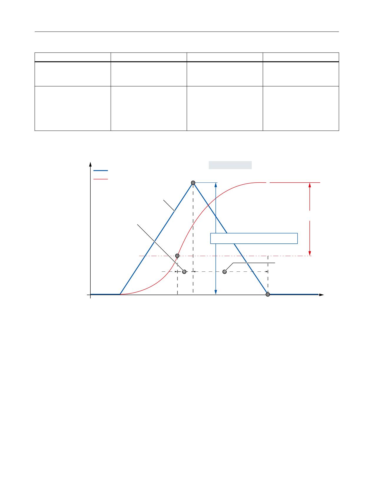
Commissioning
10.6 Acceptance test
Safety function
Test initiated by
Function checked using
Represented using
SBC / SBT
Test stop initiated e.g. by re-
Servo trace:
ducing the test stop time or
(actual value active encoder,
separate key
torque)
F_DP communication
F_DP communication inter-
Diagnostics display
rupted e.g. by withdrawing
the PROFIBUS/PROFINET con-
nector
Switching operations at the
SGE/SGA
Recommendation to measure the stopping distance/speed increase for the acceptance test
6WRSSLQJ GLVWDQFH UHVSRQVH GLVWDQFH EUDNLQJ GLVWDQFH
$FWXDO VSHHG LGHDO FDVH
3RVLWLRQ DFWXDO YDOXH
/LPLW YDOXH H[FHHGHG DW WLPH W
6WRSSLQJ GLVWDQFH
6\VWHP UHVSRQVH WLPH
5HVSRQVH DW WLPH W
6SHHG LQFUHDVH
$FWLYH 6%+ OLPLW
%UDNLQJ WLPH VWDQGVWLOO
DW WLPH W
W
W
W
7LPH
Figure 10-13
Exceeding SBH
Safety Integrated (system-integrated)
Function Manual, 10/2020, 6FC5397-4BP40-6BA2
545
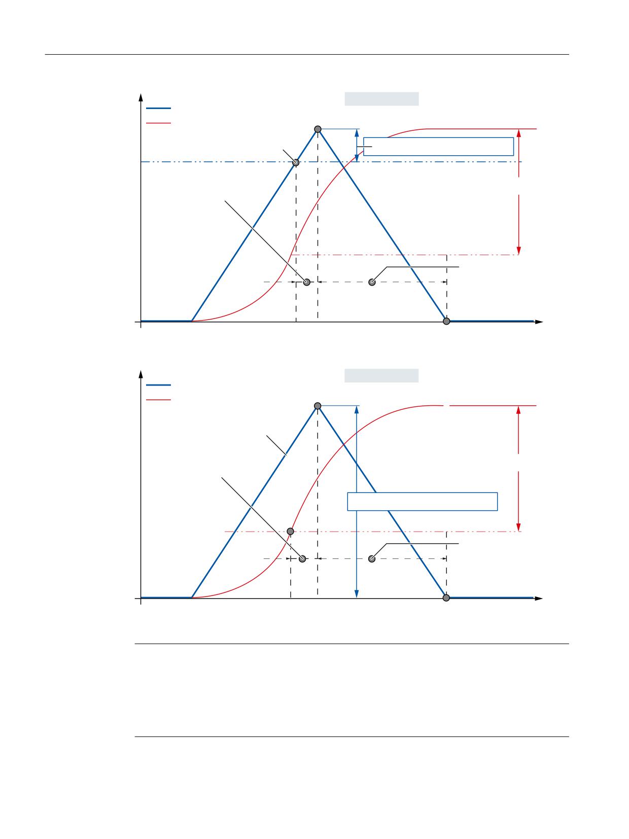
Commissioning
10.6 Acceptance test
6WRSSLQJ GLVWDQFH UHVSRQVH GLVWDQFH EUDNLQJ GLVWDQFH
$FWXDO VSHHG LGHDO FDVH
3RVLWLRQ DFWXDO YDOXH
/LPLW YDOXH H[FHHGHG DW WLPH W
6SHHG LQFUHDVH
$FWLYH 6* OLPLW
6\VWHP UHVSRQVH WLPH
6WRSSLQJ GLVWDQFH
5HVSRQVH DW WLPH W
%UDNLQJ WLPH VWDQGVWLOO
DW WLPH W
W
W
W
7LPH
Figure 10-14
Exceeding SG
6WRSSLQJ GLVWDQFH UHVSRQVH GLVWDQFH EUDNLQJ GLVWDQFH
$FWXDO VSHHG LGHDO FDVH
3RVLWLRQ DFWXDO YDOXH
/LPLW YDOXH H[FHHGHG DW WLPH W
6WRSSLQJ GLVWDQFH
6\VWHP UHVSRQVH WLPH
5HVSRQVH DW WLPH W
6SHHG LQFUHDVH
6( OLPLW
%UDNLQJ WLPH VWDQGVWLOO
DW WLPH W
W
W
W
7LPH
Figure 10-15
Exceeding SE
Note
The acceptance test for SINUMERIK Operate is described in:
SINUMERIK 840D sl
Help for the acceptance test in SINUMERIK Operate Version 4.7 SP3
Safety Integrated (system-integrated)
546
Function Manual, 10/2020, 6FC5397-4BP40-6BA2

Commissioning
10.6 Acceptance test
10.6.3
Acceptance test support
In order to make it easier to carry out the acceptance test and standardize this, there is the
function "Acceptance test support" in the SinuCom NC commissioning tool".
The objective of this acceptance support is to control the creation and administration of an
acceptance report and prepare and carry out the required test steps using the appropriate
operator actions via the operator interface. The test steps required as part of the acceptance test
are not completely executed automatically but are controlled by a skilled operator. This operator
must perform the measures associated with the test step on the system being tested. The
acceptance test support provides the following:
• Support for documenting the active monitoring functions and monitoring limit values by
exporting the appropriate machine data.
• Support for documenting the checksum values.
• Standardization of the procedure when performing the test using a pre-defined checklist.
• The time and resources required for testing are reduced by preparing test procedures within
the system, automatic trace and evaluation techniques and it takes less time to acknowledge
SI alarms that are output.
Software requirements
The acceptance test support function is based on the interaction between the NCK/drive and the
SinuCom NC user interface. This means the use of this function requires that these components
must have a certain minimum software version.
SinuCom NC software Version 7.2 SP1
NCU system software version 1.3
The basic functionality of the SinuCom NC software is explained within the scope of its own
documentation. This documentation also provides information about the steps when handling
the acceptance test support function, a description of the screen forms and the menu
prompting. This is the reason that this is not handled in this documentation.
References: Commissioning/Service Tool SINUMERIK SinuCom NC (INC)
Scope of the test list
The test steps of the SI acceptance test, supported by the system, is based on the previous test
execution and comprises the following steps:
Designation
Purpose of the test step
General
Overview
Document the machine details (e.g. manufacturer, machine type,…)
Checking the forced checking procedure
Switch-off signal paths
Test the forced checking procedure of the switch-off signal paths for the NCK and
drive. (logging NCK Alarm 27002 is sufficient.)
External stops
Test the forced checking procedure of the external stop responses (that are being
used).
Qualitative function checks
Safety Integrated (system-integrated)
Function Manual, 10/2020, 6FC5397-4BP40-6BA2
547

Commissioning
10.6 Acceptance test
Designation
Purpose of the test step
Emergency Stop
Test the internal Emergency Stop functionality when executed via external stop
responses and the response to the external SPL I/O.
Function inter-relationships
Test all of the states relevant for the safety functions that should be first documen-
ted within the scope of a function table or similar (interdependency of sensor
signals, positions, modes). In this case, the following should be taken into account
- the active monitoring function for SI-monitored axes (internal safety functions)
and the switching state of safety-related external SPL output peripherals (I/O).
Quantitative function checks
SBH (Safe Operating Stop)
Check the response when provoking that the SBH limit values are violated and
define associated characteristic quantities/parameters.
SG (safely reduced speed)
Test the response when provoking that the SG limit values are violated and define
associated characteristic quantities/parameters.
SE (safe software limit switch)
Test the response when provoking that the SE limit value is violated and define
associated characteristic quantities/parameters.
SBT
When the brake is closed, the drive generates an additional torque that must not
result in any axis motion.
Completion
Completed
The test results are saved and downloaded.
The acceptance report is generated based on the test results that have been de-
termined.
SI acceptance test
The following rule applies with the start of the SI acceptance test:
• The alarm suppression possibly set in MD10094 $MN_SAFE_ALARM_SUPPRESS_LEVEL is not
taken into account.
Test step, motion monitoring
With the start of a test step of the motion monitoring (e.g. SBH, SG) the following conditions
apply:
• Alarm "Acceptance test mode active" NCK (Alarm No. 27007) and drive (fault No. C01799)
is output.
• The setpoint velocity limiting set using MD36933 $MA_ SAFE_DES_VELO_LIMIT is
deactivated. This allows the axis to be traversed in spite of the fact that the SBH monitoring
is active or a traversing speed greater than the actual SG monitoring without having to
change the selected reference (setpoint) speed limiting.
• SI power on alarms can be temporarily acknowledged with a reset so that after an SBH
response has been tested for an axis, an NCK reset does not have to be initiated for the fault
acknowledgment. This involves the acknowledgment criteria for the following alarms:
Alarm
Fault No.
Alarm text
No. NCK
Drive
27010
C01707
Tolerance for Safe Operating Stop exceeded
27023
C01701
STOP B initiated
27024
C01700
STOP A initiated
Safety Integrated (system-integrated)
548
Function Manual, 10/2020, 6FC5397-4BP40-6BA2
Commissioning
10.6 Acceptance test
• Traversing motion is possible in spite of the external Stop C/D. This means that it is also
possible to test the active SBH monitoring state that results from an external Stop.
• An active stop in another axis does not result in a traversing inhibit for the axis being tested
- also for the setting MD36964 $MA_SAFE_IPO_STOP_GROUP = 0 for this axis.
• When traversing the axes using the JOG buttons, then the set speed limits are ignored - such
as e.g. MD32020 $MA_JOG_VELO - and the G0 value is activated as effective limit value
(maximum axis speed).
• The single-channel software limit switches (set positions, refer to MD36100 to MD36130)
are deactivated when testing SE. This means that an axis can pass these software limit
switches without having to change the associated machine data.
Prerequisites for the test step motion monitoring
A test step of the motion monitoring becomes active under the following conditions:
• There is no active SI power on alarm for the axis to be tested.
• The pulses of the axis to be tested are enabled.
• JOG is active as NC operating mode.
• The SI monitoring function selected when carrying out the test step is active, i.e. if for
example the SG2 test is selected as test, then if SG1 is active, the acceptance test mode is not
active.
• Both monitoring channels (NCK, drive) allow the mode to be activated. The state that is
assumed is subject to a crosswise data comparison between the NCK and drive.
A test step is cancelled by the following conditions:
• As a result of an NCK Reset
• When an internal timer value expires, that defines the maximum time that the state can be
active.
This time value is set in machine data MD36958 $MA_SAFE_ACCEPTANCE_TST_TIMEOUT
(NCK) and parameter p9558: SI Motion, acceptance test mode, time limit.
Trace techniques
A test is carried out prompted step-by-step using the SinuCom NC operator interface. There are
various trace techniques, which can be used to confirm and log as to whether the test was
successfully completed.
Text entry by the operator
A table or cell for the user documentation is provided for the test. This should then be completed
corresponding to the specifications. In addition to how the test is initiated, the text entry
includes, e.g. a description of test situations and responses or similar.
Alarms that occur are automatically logged
Specific system and user alarms expected for the test step that are automatically logged after the
data trace function has been started. After the appropriate data has been traced, the selection
of alarms to be logged can be reduced to those alarms that are relevant for the specific test step.
Safety Integrated (system-integrated)
Function Manual, 10/2020, 6FC5397-4BP40-6BA2
549
Commissioning
10.6 Acceptance test
Internal trace function to record signal characteristics
The SinuCom NC internal trace function is started when the data trace is started and the signals,
relevant for the specific test step, recorded. The trace is either automatically ended or the user
ends it for some tests (external stops, Emergency Stop).
Specific NC machine data must be set in order that the trace function can be used. This prepares
the appropriate resources for the function. The values to be set should be taken from the
SINUMERIK SinuCom NC start-up tool.
Basic operating information and instructions
•
The operator is prompted, step-by-step when carrying out a test. The following limitations/
constraints must be observed, especially for those tests that use the internal trace function:
- If a traversing direction has been selected, then this must also be taken into account for
the subsequent task. The reason for this is that the trigger condition for the automatic
data acquisition and evaluation is based on this direction data.
- A procedure is initiated to activate the trace function using the button <start data
acquisition>. This can take several seconds. The signal is only acquired after the
appropriate feedback has been received in a message box.
- If the trace has to be manually terminated, then this step should, if at all possible, be made
directly after the last expected signal change that is relevant for the trace. This ensures
that the relevant area is optimally displayed in the subsequent trace display.
•
For each test step, the operator must decide as to whether the test was successfully carried
out. He should make this decision based on traced and determined data and test situations
that have been carried out and documented. This can be confirmed after the test has been
carried out by selecting the appropriate results.
•
The test list, provided and supported by SinuCom NC includes the basic test steps to be
carried out. Depending on the machine configuration, several tests may not be necessary for
the particular machine. This can be selected in the basic screen of the test step. Further, there
are test cases, that are required for the machine but are not (or still not) included within the
scope of the test list, e.g. measuring the braking travel when a light barrier is obstructed, or
similar. These tests should still be manually performed.
•
When generating the acceptance certificate, for documentation purposes, data is
automatically retrieved from some machine data (SI limit values, checksums, hardware
information).
Further, the results of the tests that were carried out are incorporated in the document. The
report is structured the same as the document that was previously manually created. Some
sections, such as for example, the machine overview, function table of the configured safety
functions etc., that are not standardized, are still manually incorporated in the document at
a later date.
Safety Integrated (system-integrated)
550
Function Manual, 10/2020, 6FC5397-4BP40-6BA2

Commissioning
10.7 Replacing a motor or encoder
10.7
Replacing a motor or encoder
WARNING
Changes or replacement of hardware and/or software components
After hardware and/or software components have been changed or replaced, it is only
permissible to boot the system and activate the drives when the protective devices are closed.
It is not permissible that personnel are present within the danger zone.
Depending on the change or replacement, it may be necessary to carry out a new, partial or
complete acceptance test (see Chapter "Acceptance test (Page 537)").
Before persons may re-enter the hazardous area, the drives should be tested to ensure that they
exhibit stable behavior by briefly moving them in both the plus and minus directions (+/-). It is
especially important to carefully observe this for high-dynamic linear and torque motors.
WARNING
New axis calibration
After the measuring system has been replaced - regardless of whether it is a direct or an indirect
system - the relevant axis must be re-calibrated.
Note
After SI relevant hardware has been replaced, this must be acknowledged using softkey
"Acknowledge SI HW". The procedure is logged in file "Confirm_SI_HW.log" - and is saved in the
HMI file system under.../user/sinumerik\hmi\data\safety.
Example for the structure and content of Confirm_SI_HW.log:
<Start of file>
===================================================================
Confirm_SI_HW.log
===================================================================
Date: <yyyy>/<mm>/<dd>
Axis/drive: <Axis/drive identifiers as in the axis/drive-specific HMI screen forms>
Checksum: MD36998[1], $MA_SAFE_ACT_CHECKSUM[1] = value in the hexadecimal notation>
===================================================================
<End of file>
Description
The following information essentially refers to replacing a motor encoder. The limitations that
apply as well as the procedures are essentially the same when replacing a direct measuring
system.
When service is required (motor defective or encoder defective), it might be necessary to
completely replace the motor or just the motor encoder.
Safety Integrated (system-integrated)
Function Manual, 10/2020, 6FC5397-4BP40-6BA2
551
Commissioning
10.7 Replacing a motor or encoder
In this case, the motor encoder must be re-calibrated. This influences the behavior of Safety
Integrated if the functionality "safe limit positions" or "Safe Cams" have been activated for the
axis in question, i.e. the axis has the status "safely referenced". Depending on which motor
measuring system is used, it might be necessary to select a different procedure.
The procedure for replacing a motor with absolute value encoder and to replace a motor with
incremental encoder are described in the following text. The end of the Chapter discusses 2-
encoder systems and encoder modules.
Supplementary conditions
As mentioned above, the functionality "safe limit positions" or "Safe Cams" is active for the axis
in question.
The user agreement is set for the axis. This means that the axis has had the status "safely
referenced" at least once - the actual position value of the NC and the SI actual values (axis/drive)
have been appropriately calibrated/aligned.
"Safe limit positions" or "Safe Cams" have been able to be used. A motor or motor encoder has
to be replaced under these general conditions.
Replacing a motor with absolute value encoder
In order to setup the encoder, the offset between the machine zero and the zero of the absolute
encoder was determined.
The calibrated/aligned state is identified using MD34210 $MA_ENC_REFP_STATE = 2.
The important factor when replacing a motor (also without Safety Integrated) is that a defined
position reference can be established with respect to the mechanical parts of the machine. For
example, by mounting and removing the motor at a defined mechanical position or
appropriately re-calibrating the system after the motor has been replaced.
After the old motor has been removed and the new motor installed, another actual position
value is read by the new absolute value encoder (there is no longer a defined reference to the
correctly calibrated actual position value).
Therefore, the following error profile appears when the control boots:
Alarm 27001 Axis <Axis name> error in a monitoring channel, code 1003, values: NCK x, drive
y.
The comparison between the saved stop position and the actual position indicates a larger
deviation than specified in MD36944 $MA_SAFE_REFP_POS_TOL or parameter p9544 "SI Motion
actual value comparison tolerance (referencing)"
The alarm results in a STOP B followed by a STOP A (safe pulse cancellation) for the axis involved.
Further, the user agreement is withdrawn. This means that the axis loses the status "safely
referenced" in connection with the Alarms 27000/C01797 axis <name of the axis> not safely
referenced.
Safety Integrated (system-integrated)
552
Function Manual, 10/2020, 6FC5397-4BP40-6BA2

Commissioning
10.7 Replacing a motor or encoder
The actual position value supplied by the new motor encoder has no reference to the mechanical
system. This means that the absolute value encoder must be re-aligned and set-up at this point.
Note
A safety acceptance report is generally not required after a motor has been replaced.
Re-calibration procedure
Note
After the NCK-Reset, the axis can be traversed again. Alarms 27000/C01797 "Axis not safely
referenced" are still active and indicate that the functions "safe limit positions" and "Safe Cams"
are not active in this state. For example, if the "safe limit positions" are to be used as a substitute
for hardware limit switches, then they are not functioning at this time!
1. Reset the NCK
2. Traverse the axis to the reference position, but first enter MD34010
$MA_REFP_CAM_DIR_IS_MINUS corresponding to the approach direction. (34010 should be
set to 1 if the axis is moved in the negative (minus) direction to the reference position.)
3. Set MD34100 $MA_REFP_SET_POS to the actual value of the reference position.
4. Set MD34210 $MA_ENC_REFP_STATE to 1 to activate calibration.
5. Select the axis that is to be calibrated on the machine control panel and press the RESET key
on the machine control panel.
6. Select the JOG/REF mode, enable the axis feed.
7. Corresponding to MD34010 REFP_CAM_DIR_IS_MINUS and the traversing direction to the
reference position, calibration should be started using the "+" or "-" traversing key (backlash
has been moved to through).
8. The axis does not traverse. Instead, the offset between the correct actual value (reference
position) and the actual value - supplied by the encoder - is entered in MD34090
$MA_REFP_MOVE_DIST_CORR. The actual value appears in the basic screen and the axis
signals "referenced". The value 2 is entered in MD34210 as result.
Example::
MD34010=1 (minus) and the reference position was approached in the negative (minus)
direction. This means that the "-" key must also be pressed on the machine control panel.
9. When the absolute value encoder has been recalibrated (MD34210 from 1 → 2), the axis
changes over into the "referenced" state. At this time, the new valid actual position is
accepted as the safe actual values (axis and drive).
10.Finally, with the JOG/REF machine mode active, on the HMI the "user agreement" softkey
must be pressed and the user agreement for the axis involved must be reset. Alarms 27000/
C01797 disappear and the functions "safe limit positions" and "Safe Cams" are safely active
again.
Safety Integrated (system-integrated)
Function Manual, 10/2020, 6FC5397-4BP40-6BA2
553
Commissioning
10.7 Replacing a motor or encoder
Replacing a motor with incremental encoder
The same conditions apply as when replacing a motor with absolute encoder.
To calibrate the encoder, the reference point approach is set up, e.g. using reference point cams.
This means that after the zero mark has been passed when leaving the cam, the reference point
is approached according to the offsets in MD34080 $MA_REFP_MOVE_DIST and MD34090
$MA_REFP_MOVE_DIST_CORR - and the value of the reference point is set in MD34100
REFP_SET_POS. After referencing, Alarm messages 27000/C01797 "axis not safely referenced"
disappear and the functions "safe limit positions" and "Safe Cams" are safely active.
The important factor when replacing a motor (also without Safety Integrated) is that a defined
position reference can be established with respect to the mechanical parts of the machine. For
example, by mounting and removing the motor at a defined mechanical position or
appropriately re-calibrating the system after the motor has been replaced. At this instant in time,
Alarms 27000/C01797 still do not disappear; they only disappear after the user agreement has
been set.
After the old motor has been removed and the new motor installed, the following procedure is
recommended:
Re-calibration procedure
1. Boot the control or initiate an NCK reset
2. If the JOG/REF machine mode is active on the HMI, the "user agreement" softkey must be
pressed and the user agreement for the axis involved is withdrawn to avoid Alarm 27001 axis
<Name of the axis> fault in a monitoring channel, code 1003, values: NCK x, drive y
3. After the system has booted, the JOG/REF mode is selected and the feed enable for the axis
is issued. Carry out a reference point approach for the axis involved.
4. After the reference point has been re-calibrated, the reference point approach must be re-
initiated. The axis changes over into the "referenced" state. At this time, the reference point
value is taken over as the safe actual value for the axis and drive.
5. Finally, with the JOG/REF machine mode active, on the HMI the "user agreement" softkey
must be pressed and the user agreement for the axis involved must be reset. Alarms 27000/
C01797 disappear and the functions "safe limit positions" and "Safe Cams" are safely active
again.
Safety Integrated (system-integrated)
554
Function Manual, 10/2020, 6FC5397-4BP40-6BA2
Commissioning
10.7 Replacing a motor or encoder
Note
Note regarding Point 3.
The error at a reference point approach is no more than one revolution of the motor (difference
between two zero marks). This offset is usually not critical for the mechanical parts of the
machine. If problems arise with the traversing limits because of the type of reference point
approach, then for example, set the offset values in MD34080/34090 to non-critical values.
Alarms 27000/C01797 "Axis not safely referenced" are still active and indicate that the functions
"safe limit positions" and "Safe Cams" are not active in this state. For example, if the "safe limit
positions" are to be used as a substitute for hardware limit switches, then they are not
functioning at this time!
After completion of the reference point approach, the axis goes into the "referenced" status.
However, because of the zero mark offset between the encoders, the reference position still has
to be calibrated. This means that the position reference with respect to the mechanical system
must be re-established. The system is calibrated after measuring the difference - usually in
MD34080 REFP_MOVE_DIST or MD34090 REFP_MOVE_DIST_CORR.
Comments about 2-encoder systems
Case A
1st measuring system: Incremental motor measuring system
2. Measuring system: Absolute direct measuring system
As active measuring system via the axis interface, the 2nd position measuring system (DBAx 1.5
= 0, DBAx 1.6 =1) is statically selected
In this case, motor replacement is straightforward because the NC reference point position is
only supplied with values from the 2nd measuring system (DMS). This means that in this case,
it is not necessary to recalibrate the motor measuring system.
Case B
1st measuring system: Absolute motor measuring system
2. Measuring system: Incremental, optical measuring system
As active measuring system via the axis interface, when booting, for monitoring purposes the
1st position measuring system (DBAx1.5 = 1, DBX 1.6 =0) is selected and then subsequently the
2nd position measuring system is selected (DBAx 1.5 = 0, DBX 1.6 =1).
In this case, the motor must be replaced carefully observing the Description, motor with
absolute value encoder. This is because it is necessary to recalibrate the absolute value
encoder. When re-calibrating the system, we recommend that you permanently select the 1st
position measuring system and the axis is only traversed using the motor measuring system.
Replacing the encoder modules
When replacing the encoder modules (SMC, SME, DRIVE-CLiQ encoders) or when replacing
motors with integrated encoders (motor with DRIVE-CLiQ), a change to the configuration of the
safety-related components is detected, and a request is made that a service person
acknowledges this.
Safety Integrated (system-integrated)
Function Manual, 10/2020, 6FC5397-4BP40-6BA2
555