содержание .. 78 79 80 81 ..
Инверторы серии FRENIC-AQUA. Руководство пользователя (2012 год) - часть 80
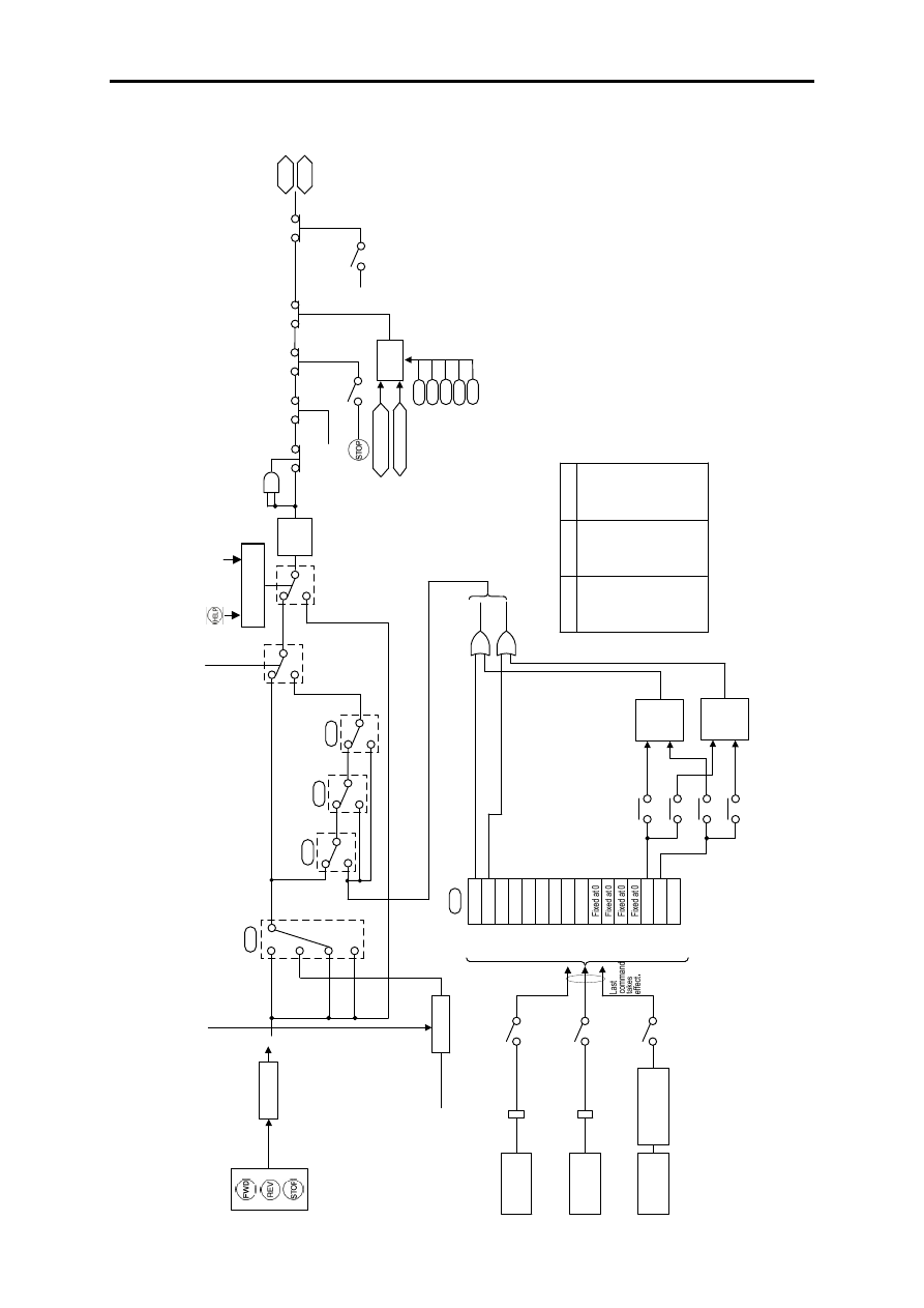
7-4
7.3
Блок
команд
привода
0
1
2
O
per
ati
on method
3
F02
Hol
d
K
eypad
Hold
E
nable 3-wire
operation
HL
D
R
un forward
FW
D
R
un reverse
RE
V
0,1,4
2,3,5 to 8
0,1
2,3
H3
0
y99
y9
8
0,1
2,3
FW
D/R
E
V
FWD
only
RE
V
only
Host
equipment
Host
equipment
Host
equipment
FW
D
RE
V
[X
1]
[X
2]
[X
6]
[X
3]
[X
4]
[X
5]
Bit
1
0
Bit
1
1
Bit
1
2
Bit
1
3
Bit
1
4
Bit
1
5
X
F
[FW
D
]
[X
7]
XR
[
R
EV]
RS
T
FW
D
P
roc
essor
RE
V
P
roces
sor
FW
D
RE
V
FWD
RE
V
FW
D
RE
V
F2
3
F25
S0
6
R
un command
Run
dec
ision
RE
V
FW
D
B
it 0
B
it 1
B
it 2
B
it 3
B
it 4
B
it 5
B
it 6
B
it 7
B
it 8
B
it 9
Truth table for S
06 (bit 13, bit 14) process
ors
bi
t 13
bit 14
Outpu
t
ON
O
N
ON
ON
OFF
O
FF
OFF
O
N
O
FF
OFF
O
FF
OFF
ON
-
ON
OFF
-
OFF
-O
N
O
N
-O
F
F
O
F
F
*1
F16
H6
3
E6
5
Field
bus card
(option)
*2
R
emote/local d
ecision
RS
-485 CO
M por
t 1
RJ
-45 c
onnector to
connec
t with key
pad
RS
-485 COM port 2
Control c
irc
uit terminals
DX
+ and D
X
-
Fi
re
mo
d
e
O
F
F
if
y
9
8=
2
,3
o
r
H
3
0
=
2
,3
,5
O
F
F
if
y
9
8
=
2
,3
or
H
3
0
=
6
t
o
8
O
F
F
if
H
3
0
=
2
,3
,5
t
o
8
O
N
if
E
98
=
9
8
O
N
if
E
9
8
=
9
9
O
N
if
E
9
9
=
9
8
O
N
if
E
9
9
=
9
9
-
:
N
o
t
a
ss
ig
n
e
d
(O
u
tp
u
ts
t
h
e
v
a
lu
e
o
f
th
e
a
ss
ig
n
e
d
b
it.
)
*1
N
ot
e
:
S
c
od
es
a
re
c
om
m
un
ic
at
io
n-
re
la
te
d
fu
nc
tio
n
co
de
s.
R
ef
er
to
th
e
R
S
-4
85
C
om
m
un
ic
at
io
n
U
se
r's
M
an
ua
l
fo
r
de
ta
ils
.
*2
F
or
d
et
ai
ls
o
f t
h
e
op
tio
ns
, r
ef
er
to
th
e
in
st
ru
ct
io
n
m
an
ua
l
fo
r
ea
ch
o
pt
io
n.
F
o
rc
e
d
t
o
O
F
F
if
b
o
th
=
O
N
S
ta
rt
in
g
f
re
q
u
en
cy
1
S
to
p
fr
e
q
u
e
n
cy
F
re
q
u
e
n
cy
li
m
ite
r
(L
o
w
)
Lo
w
li
m
ite
r
R
e
fe
re
n
ce
lo
ss
d
e
te
ct
io
n
O
N
if
H
9
6
=
1
,3
F
re
q
u
e
n
cy
co
m
m
a
nd
F
o
rc
e
t
o
s
to
p
S
T
O
P
D
e
te
ct
e
d
s
pe
e
d
O
N
if
H
7
2=
1
M
a
in
p
ow
e
r
lo
ss
d
e
te
ct
io
n
E
n
a
b
le
co
m
m
u
n
ic
a
tio
ns
li
n
k
vi
a
R
S
-4
8
5
o
r
fie
ld
b
u
s
L
E
K
e
yp
a
d
S
e
le
ct
lo
ca
l
(k
ey
p
a
d
)
o
p
e
ra
tio
n
L
O
C
C
o
m
m
u
n
ic
a
tio
n
s
lin
k
fu
n
ct
io
n
L
o
a
d
e
r
lin
k
fu
n
ct
io
n
B
u
s
lin
k
fu
n
ct
io
n
*1
Рисунок
7.2
Блок
команд
привода