Hyundai Excavator R210LC-7. Service and repair manual - page 27
8-5
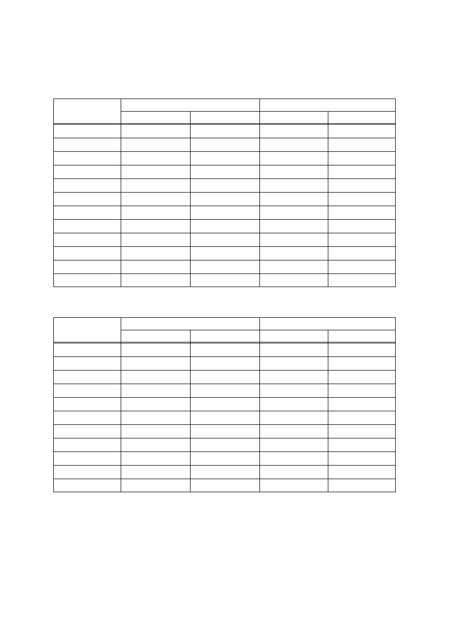
2. TORQUE CHART
Use following table for unspecified torque.
BOLT AND NUT - Coarse thread
1)
Bolt size
M 6
1.0
M 8
1.25
M10
1.5
M12
1.75
M14
2.0
M16
2.0
M18
2.5
M20
2.5
M22
2.5
M24
3.0
M30
3.5
M36
4.0
0.85 ~ 1.25
2.0 ~ 3.0
4.0 ~ 6.0
7.4 ~ 11.2
12.2 ~ 16.6
18.6 ~ 25.2
25.8 ~ 35.0
36.2 ~ 49.0
48.3 ~ 63.3
62.5 ~ 84.5
124 ~ 168
174 ~ 236
lbf ft
6.15 ~ 9.04
14.5 ~ 21.7
28.9 ~ 43.4
53.5 ~ 79.5
88.2 ~ 120
135 ~ 182
187 ~ 253
262 ~ 354
350 ~ 457
452 ~ 611
898 ~ 1214
1261 ~ 1703
kgf m
1.14 ~ 1.74
2.73 ~ 4.12
5.5 ~ 8.3
9.8 ~ 15.8
16.7 ~ 22.5
25.2 ~ 34.2
35.1 ~ 47.5
49.2 ~ 66.6
65.8 ~ 98.0
85.0 ~ 115
169 ~ 229
250 ~ 310
lbf ft
8.2 ~ 12.6
19.7 ~ 29.8
39.8 ~ 60
71 ~ 114
121 ~ 167
182 ~ 247
254 ~ 343
356 ~ 482
476 ~ 709
615 ~ 832
1223 ~ 1655
1808 ~ 2242
8T
10T
BOLT AND NUT - Fine thread
2)
Bolt size
M 8
1.0
M10
1.25
M12
1.25
M14
1.5
M16
1.5
M18
1.5
M20
1.5
M22
1.5
M24
2.0
M30
2.0
M36
3.0
kgf m
2.17 ~ 3.37
4.46 ~ 6.66
7.78 ~ 11.58
13.3 ~ 18.1
19.9 ~ 26.9
28.6 ~ 43.6
40.0 ~ 54.0
52.7 ~ 71.3
67.9 ~ 91.9
137 ~ 185
192 ~ 260
lbf ft
15.7 ~ 24.3
32.3 ~ 48.2
76.3 ~ 83.7
96.2 ~ 130
144 ~ 194
207 ~ 315
289 ~ 390
381 ~ 515
491 ~ 664
990 ~ 1338
1389 ~ 1879
kgf m
3.04 ~ 4.44
5.93 ~ 8.93
10.6 ~ 16.0
17.9 ~ 24.1
26.6 ~ 36.0
38.4 ~ 52.0
53.4 ~ 72.2
70.7 ~ 95.7
90.9 ~ 123
182 ~ 248
262 ~ 354
lbf ft
22.0 ~ 32.0
42.9 ~ 64.6
76.6 ~ 115
130 ~ 174
193 ~ 260
278 ~ 376
386 ~ 522
512 ~ 692
658 ~ 890
1314 ~ 1795
1893 ~ 2561
8T
10T
kgf m