Hyundai Excavator R210LC-7. Service and repair manual - page 26
8-150
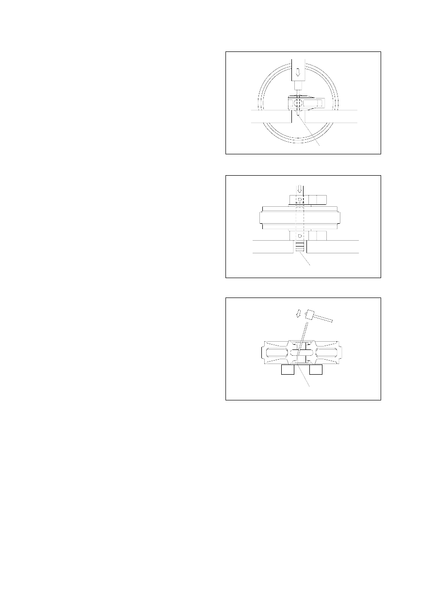
Press
7
2
4
Press
Remove the bushing(4) from idler, using
a special tool.
Only remove bushing if replacement is
necessity.
Pull out the shaft(2) with a press.
Remove seal(3) from idler(1) and bracket
(5).
Remove O-ring(6) from shaft.
Disassembly
Remove plug and drain oil.
Draw out the spring pin(7), using a press.
(2)