KTM LC4 400-660LC42003 engine. Manual - part 26
Repair manual KTM LC4
Art.-Nr
. 3.206.006 -E
10-5D
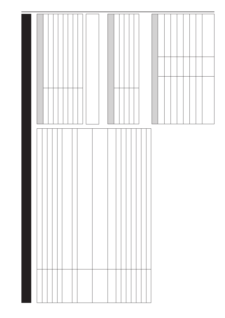
TECHNICAL SPECIFICA
TIONS - CHASSIS 400/540 SXC ‘98
400
/540 SXC
Frame
Central chr
ome-moly-steel frame
Fork
WP
Extr
eme
Wheel travel fr
ont/r
ear
285/320 mm (11,2/12,6 in)
Rear suspension
Central shock absorber (WP)
with PRO-LEVER linkage to r
ear
-swingarm with needle bearing
Fr
ont brake
Disc brake with carbon-steel brake disc , brake caliper floated
brake disc
Ø
= 260 mm (10,2 in)
Rear brake
Disc brake with carbon-steel brake disc
Ø
220 mm (8,7 in), brake caliper floated
Ty
re
sf
ront
90/90
- 2
1
Air pr
essur
e of
fr
oad
1,0 bar (14 psi)
Air pr
ess. r
oad, driver only
1,5 bar (21 psi)
Air pr
ess. r
oad with passenger
–
Ty
res r
ear
140/80
- 1
8
Air pr
essur
e of
fr
oad
1,2 bar (17 psi)
Air pr
ess. r
oad, driver only
2,0 bar (28 psi)
Air pr
ess. r
oad with passenger
–
Fuel tank capacity
9 liter (3 US
gallons)
of that 1,5 liter (0,4 US
gallons) r
eserve
Final drive ratio
400: 14:50 540:15:50
Chain
5
/
8
x
1
/
4
" O-Ring
Steering angle
62,5°
Wheel base
15
10
±
10
mm (59,4
±
0,4 in)
Seat high
940 mm (37 in)
Gr
ound clearance
350 mm (13,8 in)
Dead weight without fuel
400: 121 kg (267 lbs) 540: 122 kg (269 lbs)
Collar bolt fr
ont axle
M 1
0
40 Nm
(30 ft.lb)
Brake caliper fr
ont
M 8
Loctite 243 + 25 Nm
(18 ft.lb)
Collar nut r
ear axle
M 20x1
,5
80 Nm
(59 ft.lb)
Hex. nut swing arm bolt
M 1
4
x1
,5
100 Nm
(74 ft.lb)
Clamping bolt top triple clamp
M 8
15 Nm
(11 ft.lb)
Clamping bolt bottom triple clamp
M 8
20 Nm
(15 ft.lb)
Clamping bolts fork leg axle passage
M 8
10 Nm
(7,4 ft.lb)
Other bolts chassis
M 6
10 Nm
(7,4 ft.lb)
M 8
25 Nm
(18 ft.lb)
M 10
45 Nm
(33 ft.lb)
TORQUES
WP 09.18.S7.44
Compr
ession adjuster
12
Rebound adjuster
12
Spring
4,2 N/mm
Spring pr
eload
7 mm
Air chamber length
155 mm
Capacity per fork leg
ca 800 ccm
Fork oil
SAE 5
ST
ANDARD ADJUSTMENT - FORK
NOTE FOR WHITE POWER FORKS:
The damping units in the left and the right fork leg ar
e of dif
fer
ent design. Make
sur
e not to mix them up in case of r
epair or service works.
WP 01.18.Q7.82
Compr
ession adjuster
3
Rebound adjuster
4
Spring
63/260
Spring pr
eload
23 mm
ST
ANDARD-ADJUSTMENT - SHOCK ABSORBER