BMW AG Motorcycle (K1100LT, K1100RS). Manual - part 28
 

  Index      Manuals     BMW AG Motorcycle (K1100LT, K1100RS). Repair Manual


Search            


Content   ..  26  27  28  29   ..


BMW AG Motorcycle (K1100LT, K1100RS). Manual - part 28


32.5

Removing and installing left and 
right handlebar fittings

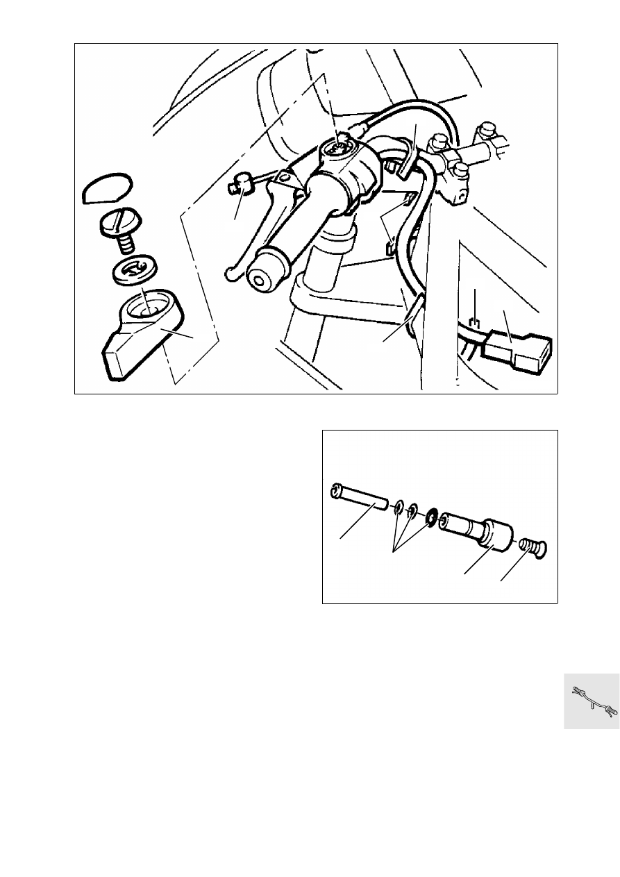
Removing and installing left handlebar 
fitting

•

Remove fuel tank.

•

[LT] 

Cut through cable clip (1)

•

Disconnect plug connection for clutch switch (2).

•

Detach cold start operating cable at lever (3).

•

Detach clutch cable (4) at clutch release lever, 
then at handlebar lever.

Removing and installing handlebar weight 

•

Release countersunk screw (1)

•

Pull out handlebar weight (2).

•

Pull out threaded sleeve (3) with screw.

•

Note O-ring (4).

LT320010

3

4

2

1

1

1

1

LT320020

1

2

3

4

32.6

•

Cut open rubber grip (1) and remove.

•

Release multifunction switch (2).

•

Loosen clamping screw (3) of handlebar fitting.

•

Remove fitting from handlebar.

•

Install in the reverse order of removal.

L

 Note:

Bond rubber grip with Loctite 454 on handlebar.

X 

Tightening torque:

Clamping screw, handlebar fitting

.................. 5 Nm

Settings:

Clutch play at handlebar lever

...............4 ± 0.5 mm

............................................. (0.15748 ± 0.0197 in)

Cable length at clutch release lever

.......75 ± 1 mm 

............................................. (2.95275 ± 0.0394 in)

LT320030

1

3

2

32.7

Removing and installing right handle-
bar fitting

•

Remove fuel tank.

•

[LT] Cut through cable clip (1).

•

Disconnect plug connection (2) for brake light 
switch.

•

Release brake line (3) and close off.

•

Release multifunction switch (4).

•

Loosen cover (5) for accelerator cable.

•

Detach accelerator cable (6).

•

Remove handlebar weight (7).

•

Loosen clamping screw (8) from fitting housing.

•

Remove fitting.

•

Cut through rubber grip and remove.

•

Install in the reverse order of removal.

e

 Caution:

Top up brake fluid, vent system!

L

 Note:

Turn connection piece (3) of the brake line such that 
the brake line does not chafe at any point when the 
handlebar is turned.

X 

Tightening torques:

Brake line ........................................................7 Nm
Bleed screw.....................................................7 Nm
Clamping screw...............................................5 Nm

Setting:

Accelerator cable play

............. 0.75 mm (0.0295 in)

LT320040

3

1

1

4

4

2

1

LT320050

8

7

6

5

32.8

Removing and installing handlebar

•

Remove fuel tank.

•

Remove handlebar cover (1).

•

Disconnect plug connections for switches.

•

Remove left and right handlebar fittings.

•

Release top sections of clamping block (2).

•

Install in the reverse order of removal.

X 

Tightening torque:

Clamping screws

.......................................... 22 Nm

LT320060

1

2

32.9

Removing and installing handlebar 
clamping blocks

•

Remove stop plate (3).

•

Remove clamping blocks (4).

•

Drive out handlebar mounting with drift.

•

Install in the reverse order of removal.

X 

Tightening torque:

Clamping block

............................................ 16 Nm

LT320070

4

3

32.10

Removing and installing accelera-
tor cable

•

Remove fuel tank.

•

Remove cable cover (1) on handlebar fitting.

•

Detach cable.

•

Turn in cam disc on throttle stub pipe (2) and de-
tach cable.

•

Install in the reverse order of removal.

L

 Note:

When installing, first attach cable at cam disc. Fit ca-
ble without kinks.

•

Adjust cable play at adjusting screw (3).

Accelerator cable play:

Desired value

.......................... 0.75 mm (0.0295 in)

LT320080

1

3

2

32.11

Removing and installing clutch 
cable

•

Remove fuel tank.

•

Detach clutch cable (1) at clutch release lever.

•

Pull clutch hand lever and press out nipple (2).

•

Unscrew set screw (3) from fitting housing.

•

Cut through cable clip and pull out operating 
cable.

•

Install in the reverse order of removal.

L

 Note:

Ensure the operating cable is fitted correctly, with 
no kinks.

•

Adjust cable after fitting.

Settings:

Play at handlebar lever

.........................4 ± 0,5 mm

............................................. (0.15748 ± 0.0197 in)

Cable length at clutch release lever

.......75 ± 1 mm

............................................. (2.95275 ± 0.0394 in)

Adjusting instructions:
See Group 00, “Checking clutch operating clear-
ance, adjusting if necessary”.

LT320090

1

2

3

32.12

Removing and installing operating 
cable for increasing starting speed

•

Remove fuel tank.

•

Remove operating lever (1).

•

Detach cable (2).

•

On throttle rail, release locknut (3) from adjusting 
screw (4) and unscrew adjusting screw.

•

Detach nipple (5).

•

Remove cable by pulling from below.

•

Install in the reverse order of removal.

L

 Note:

Fit cable without kinks. Check setting of start speed 
increase.

Adjusting instructions:
See Group 00, “Checking clutch operating clear-
ance, adjusting if necessary”.

LT320100

4

2

3

5

1


Content   ..  26  27  28  29   ..