BMW AG Motorcycle (F 650 GS). Manual - part 37
 

  Index      Manuals     BMW AG Motorcycle (F 650 GS). Repair Manual


Search            


Content   ..  35  36  37  38   ..


BMW AG Motorcycle (F 650 GS). Manual - part 37


61.10

X 

Tightening torques:

Intake air silencer to retainer .......................... 9 Nm
Intake air silencer to oil tank ........................... 9 Nm
Connecting flange .......................................... 5 Nm
Fasteners, cover/
trim panel for turn indicator ............................ 3 Nm
Lid of electronic equipment box ..................... 4 Nm
Electronic equipment box to frame................. 5 Nm
Expansion tank to radiator.............................. 9 Nm
Ignition coil to cylinder head........................... 9 Nm

61 31 906 

Removing and installing 

coolant-temperature sensor

See Group 17

61 31 302 

Removing and installing side 

stand switch

–

Place motorcycle on its centre stand.

–

Remove the engine guard.

•

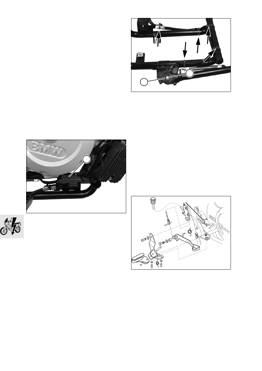
Disconnect side-stand switch plug (1) and unclip 
the plug.

•

Disconnect plug of oxygen sensor.

•

Remove lower section.

•

Cut the cable ties at the lower section (arrows).

•

Remove retaining ring (2).

•

Lift switch (3).

•

Disconnect plug of switch (3).

•

Installation is the reverse of the removal proce-
dure.

X 

Tightening torques:

Lower section to engine shell....................... 21 Nm
Lower section to main frame ........................ 21 Nm
Engine guard to frame.................................... 9 Nm

61 31 310 

Removing and installing 

rear-brake switch for brake light

–

Remove seat.

–

Remove right cover.

•

Remove brake-light switch (4).

•

Cut through the cable tie at the frame.

•

Remove the fuse box.

E610050

1

E610040

3

2

E340040

4

61.11

•

Remove the fastener securing the plug of the 
brake-light switch (arrow) at the frame

•

Disconnect plug of brake light switch.

•

Installation is the reverse of the removal proce-
dure.

X 

Tightening torques:

Brake light switch, footbrake, to frame ........... 5 Nm

61 31 300 

Removing and installing 

front-brake switch for brake light

–

Place motorcycle on its centre stand.

–

Remove seat.

–

Remove left, right and centre covers.

•

Remove brake-light switch (1).

•

Cut through cable clip.

•

Disconnect the expansion tank and pull it to one 
side.

•

Remove the fasteners securing the oil tank and 
allow the oil tank to dangle to one side on the 
hoses.

•

Remove the starter relay from the holder.

•

Remove the lid of the electronic equipment box.

•

Cut through the cable tie holding the wiring har-
ness at the electronic equipment box.

•

Disengage cover from the anchorage on main 
frame on left.

•

Disconnect plug of brake light switch (2).

•

Push the cover over the cylinder head slightly to 
one side and remove the connector.

X 

Tightening torques:

Oil tank to intake air silencer .......................... 9 Nm
Lid of electronic equipment box ..................... 4 Nm
Expansion tank to radiator ............................. 9 Nm
Brake-light switch to handlebar fitting ............ 3 Nm

E610060

E610070

1

E610030

2

61.12

61 33 000 

Removing and installing 

horn

–

Remove front mudguard.

a

....................................................See Group 46

•

Disconnect plug for horn (2).

•

Remove fastener securing horn (1).

•

Installation is the reverse of the removal proce-
dure.

X 

Tightening torques:

Horn to bottom fork bridge ........................... 18 Nm
Lid of electronic equipment box ..................... 4 Nm
Front mudguard to fork bridge........................ 3 Nm

61 31 227 

Removing and installing 

idle-indicator switch

–

Remove cover for chain drive sprocket.

•

Remove fastener securing cable to idle-indicator 
switch.

•

Remove idle switch (3).

•

Installation is the reverse of the removal proce-
dure: pay particular attention to the following.

•

Clean the threads of the idle-indicator switch and 
coat with Loctite 243.

X 

Tightening torques:

Idle-indictor switch
(clean thread + Loctite 243)............................ 3 Nm

Removing and installing front and 
rear ABS sensors

See Group 34

E610080

2

1

E610090

3

62.1

Contents

Page

62

Technical Data

............................................................................................................................... 3

Telltale/warning lights 

...............................................................................................................5

Removing and installing instrument panel 

.....................................................................6

Replacing telltale/warning lights 

.........................................................................................6

Disassembling and assembling instrument cluster

 .........................................................6

Removing and installing wiring harness

 ................................................................................7

62 Instruments

62.2

62.3

62

Technical Data

F 650 GS

Instruments

Speedometer and revolution counter lighting

W5/1.2 - 12V 1.2W

Telltale and warning lights

Flashing turn indicator

Idle

Oil pressure

Water temperature

High (main) beam headlight

ABS

Fuel gauge

W5/1.2 - 12V 1.2W

W5/1.2 - 12V 1.2W

W5/1.2 - 12V 1.2W

W5/1.2 - 12V 1.2W

W5/1.2 - 12V 1.2W

W5/1.2 - 12V 1.2W

W5/1.2 - 12V 1.2W

62.4

62.5

Telltale/warning lights

1 Water temperature
2 Oil pressure
3 Idle
4 High (main) beam headlight
5 Fuel gauge
6 ABS
7 Flashing turn indicator
8 Speedometer lighting
9 Revolution counter lighting

E620050

1

2

4

6

7

3

5

9

8


Content   ..  35  36  37  38   ..