Motorcycle BMW R1150RT. Manual - part 49
 

  Index      motorcycles     Motorcycle BMW R1150RT - service repair manual 2001 year


Search            


Content   ..  47  48  49  50   ..


Motorcycle BMW R1150RT. Manual - part 49


23.20

23 11 

Checking and adjusting fully 

assembled length of gearbox shafts 
and selector drum

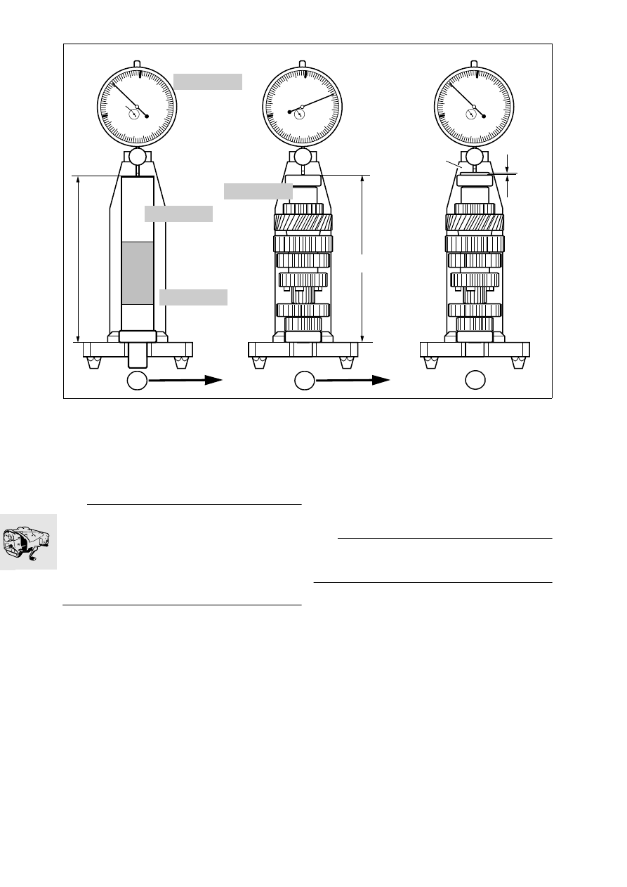
Checking and adjusting fully assembled length 
of intermediate shaft 

e

 Attention:

Check and adjust the fully assembled length as de-
scribed below and install a spacing washer of the 
correct thickness.
Before measuring, always make sure that the 
grooved ball bearings are pressed fully home, even 
if the shaft has not been disassembled and reas-
sembled.

•

Position dial gauge, BMW No. 23 4 762, in rear 
locating bore of stand, BMW No. 23 4 761, and 
set to 0.2 mm (0.0078 in) preload.

•

Using dial gauge, zero to dimension “A” of the 
zero gauge, BMW No. 23 4 763.

•

Pull off the input-side grooved ball bearing with 
universal puller, BMW No. 00 7 500.

•

Remove the spacing washer.

•

Place reference washer, BMW No. 23 4 765, on 
the intermediate shaft.

•

Place the grooved ball bearing on the reference 
washer.

•

Insert intermediate shaft in measuring stand. 

•

Using the dial gauge, measure the deviation from 
zero of dimension “B” at 
the inner bearing race. 

Deviation from zero is equivalent to the thickness 
“C” of spacer (1).

•

Place spacer (1) of correct thickness on 
inner bearing race and check deviation from ze-
ro.

A = B + C

e

 Attention:

The maximum deviation from zero must not be ex-
ceeded.

•

Remove the intermediate shaft from the measur-
ing fixture.

•

Remove spacing washer, grooved ball bearing 
and reference washer.

•

Place a spacing washer (1) of the correct thick-
ness on the intermediate shaft and press on the 
grooved ball bearing.

Reference dimension for intermediate shaft:
The maximum permissible deviation from zero is 

........................ -0.05…0.00 mm (-0.0019…0.00 in)

0

90

10

20

30

40

50

60

70

80

0

90

10

20

30

40

50

60

70

80

0

90

10

20

30

40

50

60

70

80

KR230181

23 4 763

23 4 761

23 4 762

23 4 765

0.2

1

3

2

1

C

B

A

23.21

23 11 Checking and adjusting fully assembled 
length of output shaft 

e

 Attention:

Check and adjust the fully assembled length as de-
scribed below and install a spacing washer of the 
correct thickness.
Before measuring, always make sure that the 
grooved ball bearings are pressed fully home, even 
if the shaft has not been disassembled and reas-
sembled.

•

Position dial gauge, BMW No. 23 4 762, in rear 
locating bore of stand, BMW No. 23 4 761, and 
set to 0.2 mm (0.0078 in) preload.

•

Using dial gauge, zero to dimension “A” of the 
zero gauge, BMW No. 23 4 763.

•

Pull off the input-side grooved ball bearing with 
universal puller, BMW No. 00 7 500.

•

Remove the spacing washer.

•

Place reference washer, BMW No. 23 4 766, on 
the output shaft.

•

Place the grooved ball bearing on the reference 
washer.

•

Insert the output shaft into the measuring stand. 

•

Using the dial gauge, measure the deviation from 
zero of dimension “B” at the inner bearing race. 

Deviation from zero is equivalent to the 
thickness “C” of spacer (1).

•

Place spacer (1) of correct thickness on inner 
bearing race and check deviation from zero. 

A = B + C

e

 Attention:

The maximum deviation from zero must not be ex-
ceeded.

•

Remove spacing washer, grooved ball bearing 
and reference washer.

•

Place a spacing washer (1) of the correct thick-
ness on the output shaft and press on the 
grooved ball bearing.

Reference dimension for output shaft:
The maximum permissible deviation from zero is 

........................ -0.05…0.00 mm (-0.0019…0.00 in)

0

90

10

20

30

40

50

60

70

80

0

90

10

20

30

40

50

60

70

80

0

90

10

20

30

40

50

60

70

80

KR230300

23 4 763

23 4 761

23 4 762

23 4 766

0.2

1

3

2

1

C

B

A

23.22

23 11 Checking and adjusting fully assembled 
length of input shaft 

e

 Attention:

Check and adjust the fully assembled length as de-
scribed below and install a spacing washer of the 
correct thickness.
Before measuring, always make sure that the 
grooved ball bearings are pressed fully home, even 
if the shaft has not been disassembled and reas-
sembled.

•

Position dial gauge, BMW No. 23 4 762, in front 
locating bore of stand, BMW No. 23 4 761, and 
set to 0.2 mm (0.078 in) preload.

•

Using dial gauge, zero to dimension “A” of the 
zero gauge, BMW No. 23 4 763.

•

Pull off the output-side grooved ball bearing with 
universal puller, BMW No. 00 7 500.

•

Remove the spacing washer.

•

Mount reference washer, BMW No. 23 4 764, on 
the input shaft.

•

Place the grooved ball bearing on the reference 
washer.

•

Insert input shaft with adapter disc, 
BMW No. 23 4 767, in measuring stand. 

•

Using the dial gauge, measure deviation from 
zero of dimension “B” at the inner bearing race. 

Deviation from zero is equivalent to the 
thickness “C” of spacer (1).

•

Place spacer (1) of correct thickness on inner 
bearing race and check deviation from zero. 

A = B + C

e

 Attention:

The maximum deviation from zero must not be ex-
ceeded.

•

Take the input shaft out of the measuring fixture.

•

Remove the adapter disc, spacing washer, 
grooved ball bearing and reference washer.

•

Place spacer (1) of the correct thickness in posi-
tion and press the grooved ball bearing onto the 
input shaft.

Reference dimension for input shaft:
The maximum permissible deviation from zero is 

..................................................... -0.05…0.00 mm

0

90

10

20

30

40

50

60

70

80

0

90

10

20

30

40

50

60

70

80

0

90

10

20

30

40

50

60

70

80

23 4 762

KR230290

23 4 767

23 4 764

0.2

1

2

3

23 4 763

23 4 761

1

C

B

A

23.23

23 11 Checking and adjusting fully assembled 
length of selector drum

•

Place spacing washer and both thrust washers 
on the selector drum.

•

Using slide gauge, determine fully assembled 
length “A”.

•

If necessary, adjust fully assembled length “A” 
with a shim washer (arrow).

Fully assembled length:
Selector drum

............... 111.80…111.90 mm (4.4015…4.4055 in)

KR230190

A


Content   ..  47  48  49  50   ..