Volkswagen Golf / Golf GTI / Jetta. Manual - part 1135


  Index      Volkswagen     Volkswagen Golf / Golf GTI / Jetta - service repair manual 1999-2005 year


Search            copyright infringement  


Content   ..  1133  1134  1135  1136   ..


Volkswagen Golf / Golf GTI / Jetta. Manual - part 1135


94-60


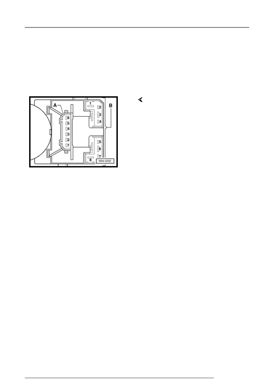
Steering column switches, 
multi-pin connector 
assignments 


Windshield wiper/washer and 
multi-function indicator (MFI) 
switches 
 

     A - Connector, 4 pin 

B - Connector, 8 pin 

1 - MFI call-up button - right 

2 - MFI call-up button - left 

3 - MFI call-up button - terminal 31
(Ground) 

4 - MFI safe switch - Reset 

5 - Windshield wiper intermittent 
regulator - to intermittent wash/wipe 
relay 

6 - Windshield wiper intermittent 
regulator - terminal 31 (Ground) 

1 - Windshield wiper switch - 
terminal 53 

2 - Windshield wiper switch - 
terminal 31 

3 - Windshield wiper switch - 
terminal 53e 

4 - Windshield wiper switch - 
terminal 53c 

5 - Windshield wiper switch - rear 
window wiper 

6 - Windshield wiper switch - 
terminal 53b 

7 - Windshield wiper switch - 
intermittent operation 

8 - Windshield wiper switch - 
terminal 53a 

Steering column switches

13/2/2005

94-61


Turn Signal, headlight, flasher and 
parking light switch 
 

     C - Connector, 12 pin 

1 - Switch for headlights/flasher - 
terminal 30 

2 - Switch for headlights/flasher - 
terminal 30 

3 - Turn Signal switch - terminal L 

4 - Parking light switch - terminal P 

5 - Turn Signal switch - terminal 49a 

6 - Horn contact - terminal 71 

7 - Switch for headlights/flasher - 
terminal 56 

8 - Switch for headlights/flasher - 
terminal 56b 

9 - Parking light switch - terminal PL 

10 - Parking light switch - terminal PR 

11 - Turn Signal switch - terminal R 

12 - Switch for headlights/flasher - 
terminal 56a 

Steering column switches

13/2/2005

94-62


Cruise control switch  

     D - Connector, 10 pin 

1 - Open 

2 - Switch for CCS - On / Off 

3 - Switch for CCS - Set / delay 

4 - Switch for CCS - Reset / 
Resume saved speed / Accelerate 

5 - Switch for CCS - Reset / 
Resume saved speed / Accelerate 

6 - Switch for CCS - On / Off 

7 - Switch for CCS 

8 - 10: Open 

Steering column switches

13/2/2005

94-63


Ignition/starter switch and 
lock cylinder  


Lock cylinder, removing and installing 


CAUTION!


Before beginning repairs on the electrical 
system:


Obtain the anti-theft radio security code.


Switch off all electrical consumers.


Switch ignition off and remove ignition 
key.


Disconnect negative ( - ) battery terminal.


When disconnecting and reconnecting 
battery terminals, observe all applicable 
Notes and torque specifications, as well as 
instructions on performing OBD program 
and electrical system function checks as 
specified in this Repair Manual 


Page 27

39

 . 


Removing  


-  Disconnect battery 


Page 27-39

 . 


-  Remove steering column switches 


Page 94

55

 . 


Note:  

If equipped, the induction coil for anti-theft 
immobilizer is integrated with the lock cylinder and 
cannot be serviced separately.
 

-  Where applicable, carefully disconnect electrical 

connection for the induction coil for anti-theft 
immobilizer from lock cylinder. 

Ignition/starter switch and lock cylinder

13/2/2005


Content   ..  1133  1134  1135  1136   ..