Suzuki Grand Vitara JB416 / JB420. Manual - part 383


  Index      Suzuki     Suzuki Grand Vitara JB416 / JB420- service repair manual


Search            


Content   ..  381  382  383  384   ..


Suzuki Grand Vitara JB416 / JB420. Manual - part 383


9E-5 Glass / Windows / Mirrors: 

Repair Instructions

Windshield Removal and Installation

S5JB0A9506001

Removal

1) Clean both inside and outside of glass and around it.
2) Remove wiper arms and cowl top garnish.
3) Remove windshield side garnish.
4) Using tape, cover body surface around glass to 

prevent any damage.

5) Remove rear view mirror, sun visor and front pillar 

trims (right & left).

6) If necessary, remove instrument panel. Refer to 

“Instrument Panel Removal and Installation in 
Section 9C”.

7) If necessary, remove head lining. Refer to “Head 

Lining Removal and Installation in Section 9H”.

8) Remove (or cut) windshield molding.
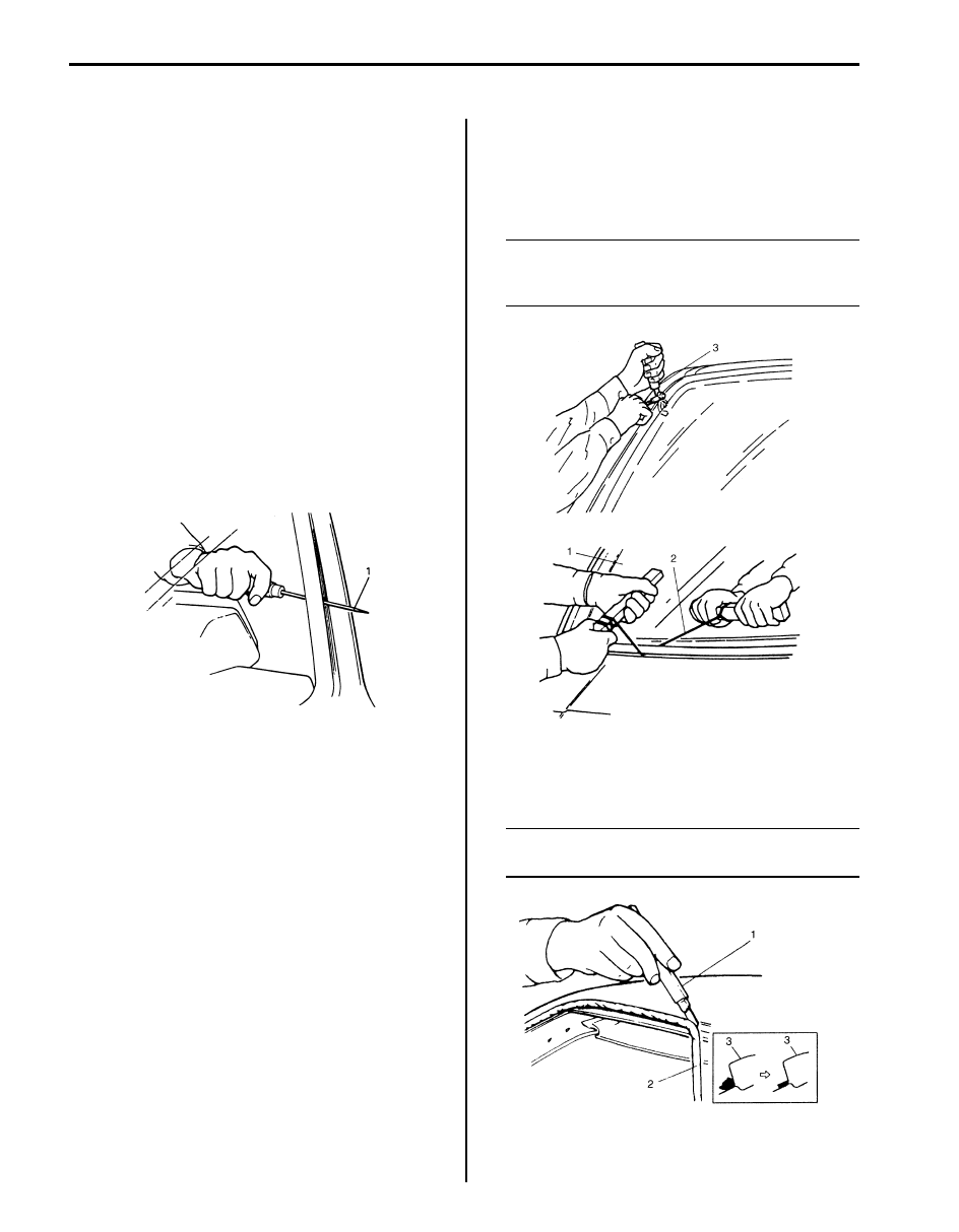
9) Drill hole with eyeleteer (1) through adhesive and let 

piano string through it.

10) Cut adhesive all around windshield (1) with piano 

string (2). When using tool, windshield knife (3), to 
cut adhesive, be careful not to cause damage to 
windshield. Use wire to cut adhesive along lower 
part of windshield.

NOTE
Use piano string (2) as close to glass as 
possible so as to prevent damage to body 
and instrument panel.


11) Using knife (1), smoothen adhesive (2) remaining on 

body side (3) so that it is 1 – 2 mm (0.039 – 0.078 
in.) thick all around.

NOTE
Before using knife (1), clean it with alcohol or 
the like to remove oil from it.


I2RH01950040-01

I3RH0A950006-01

I2RH01950042-01

Glass / Windows / Mirrors:  9E-6

12) When reusing windshield, remove the adhesive (1) 

from it, using care not to damage primer coated 
surface (2).

Installation

1) Using cleaning solvent, clean windshield edge where 

windshield glass is to be adhered. (Let it dry for more 
than 10 minutes.)

2) To determine installing position of glass (1) to body 

(2), position glass against body so that clearance 
between upper end of glass (1) and body (2) is 
approximately 5.5 mm (0.217 in.) and clearances 
between each side end (right & left) of glass (1) and 
body (2) are even. Then mark mating marks on glass 
(1) and body (2) as shown. Upper clearance can be 
adjusted by moving glass stoppers position.

Windshield clearance
“a”: approx. 5.5 mm (0.217 in.)

3) Clean contact surfaces of old adhesive (4), paint or 

bare metal thoroughly.
If surfaces of paint or bare metal come out, apply 
primer (2) for body with caution not to apply primer 
(2) to surface of adhesive remaining on body.

NOTE

• Be sure to refer to primer maker’s 

instruction for proper handling and drying 
time.

• Do not touch body and old adhesive 

surfaces where glass is to be adhered.


4) Install new molding to glass.
5) Clean glass surface to be adhered to body with 

clean cloth. If cleaning solvent is used, let it dry for 
10 minutes or more.

Cleaning Area for windshield (distance from the 
edge of glass or molding)
30 – 50 mm (1.18 – 1.97 in.)

6) Install new fastener (1) to windshield (2).

I2RH01950043-01

I5JB0A950003-01

1. Do not apply primer
3. Apply primer

I2RH01950046-01

I5JB0A950004-02

9E-7 Glass / Windows / Mirrors: 

7) Using new brush, apply sufficient amount of primer 

onto glass along glass edge.

NOTE

• Be sure to refer to maker’s instruction for 

proper handling and drying time.

• Do not apply primer on outside of ceramic 

coated surface.

• Do not touch primer coated surface.


Width applied primer for windshield
“a”: 15 mm (0.59 in.)
“b”: 20 mm (0.79 in.)

8) Apply primer for molding along molding surface all 

around.

9) Apply adhesive (1) referring to figure.

NOTE

• Press glass (2) against fittings surface of 

body panel quickly after adhesive (1) is 
applied.

• Use of rubber sucker grip is helpful to hold 

and carry glass after adhesive (1) is 
applied.

• Perform steps 8) to 9) within 10 min. to 

ensure sufficient adhesion.

• Be sure to refer to adhesive maker’s 

instruction for proper handling and drying 
time.

• Start from bottom side of glass (2).
• Be careful not to damage primer.


Adhesive amount specifications and position for 
windshield
Width “a”: Approx. 7 mm (0.27 in.)
Height “b”: Approx. 15 mm (0.59 in.)
Position “c”: Approx. 4 mm (0.15 in.)
Position “d”: Approx. 35 mm (1.38 in.) for bottom 
section

10) Holding rubber sucker grips (1), place glass onto 

body.

1. Molding
2. 21.4 mm (0.84 in.)

1

1

2

“b”

“a”

“a”

I5JB0A950005-01

3. Molding

1

2

2

2

3

3

1

3

1

3

“a”

“b”

“d”

“a”

“c”

“c”

“a”

“b”

“b”

I5JB0A950006-02

I2RH01950050-01

Glass / Windows / Mirrors:  9E-8

11) Check for water leakage by pouring water over 

windshield through hose. If leakage is found, dry 
windshield and fill leaky point with adhesive. If water 
still leaks even after that, remove glass and start 
installation procedure all over again.

NOTE

• Do not use high pressure water.
• Do not blow compressed air directly at 

adhesive applied part when drying.

• Do not use infrared lamp or like for drying.


CAUTION

!


Upon completion of installation, note the 
following.
• Sudden closing of door before adhesive is 

completely set may cause glass to become 
loose or to come off. Therefore, if door is 
opened or closed before adhesive is 
completely set, make sure to open all door 
glasses and use proper care.

• If molding is not securely in place, hold it 

down with a tape until adhesive is 
completely set.

• Each adhesive has its own setting time.
• Be sure to refer to its maker’s instruction, 

check setting time of adhesive to be used 
and observe precautions to be taken 
before adhesive is set.

• Refrain from driving till adhesive is 

completely set so as to ensure proper and 
sufficient adhesion.


Rear Quarter Window Removal and Installation

S5JB0A9506023

Removal

1) Clean both inside and outside of glass and around it.
2) Using tape, cover body surface around glass to 

prevent any damage.

3) If necessary, remove instrument panel. Refer to 

“Instrument Panel Removal and Installation in 
Section 9C”
.

4) If necessary, remove quarter under trim, center pillar 

inner upper trim, rear pillar trim and head lining. 
Refer to “Head Lining Removal and Installation in 
Section 9H”
.

5) Drill hole with eyeleteer (1) through adhesive and let 

piano string through it.

I2RH01950051-01

I2RH01950040-01


Content   ..  381  382  383  384   ..