Suzuki Grand Vitara JB416 / JB420. Manual - part 140
1K-2 Exhaust System:
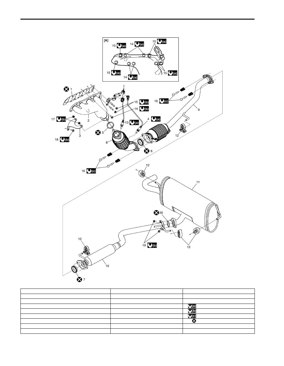
For M16 Engine Model
I5JB0A1B1002-03
[A]: Installing location of exhaust manifold bold and nut.
9. Exhaust pipe No.2
18. Exhaust pipe No.1 bracket bolt
1. Exhaust manifold gasket
10. Exhaust center pipe
19. Exhaust center pipe nut
2. Exhaust manifold
11. Muffler
20. Exhaust center pipe gasket
3. Exhaust pipe No.1 bracket
12. Mounting
: 45 N
⋅m (4.5 kgf-m, 32.5 lb-ft)
4. HO2S
13. A/F sensor
: 50 N
⋅m (5.0 kgf-m, 36.5 lb-ft)
5. Exhaust pipe No.1 gasket
14. Exhaust manifold bolt
: 43 N
⋅m (4.3 kgf-m, 31.0 lb-ft)
6. No.1 seal ring
15. Exhaust manifold nut
: Do not reuse.
7. No.2 seal ring
16. Exhaust pipe bolt
8. Exhaust pipe No.1
17. Exhaust pipe No.1 bracket nut