Suzuki Grand Vitara JB416 / JB420. Manual - part 103
1D-80 Engine Mechanical: For J20 Engine
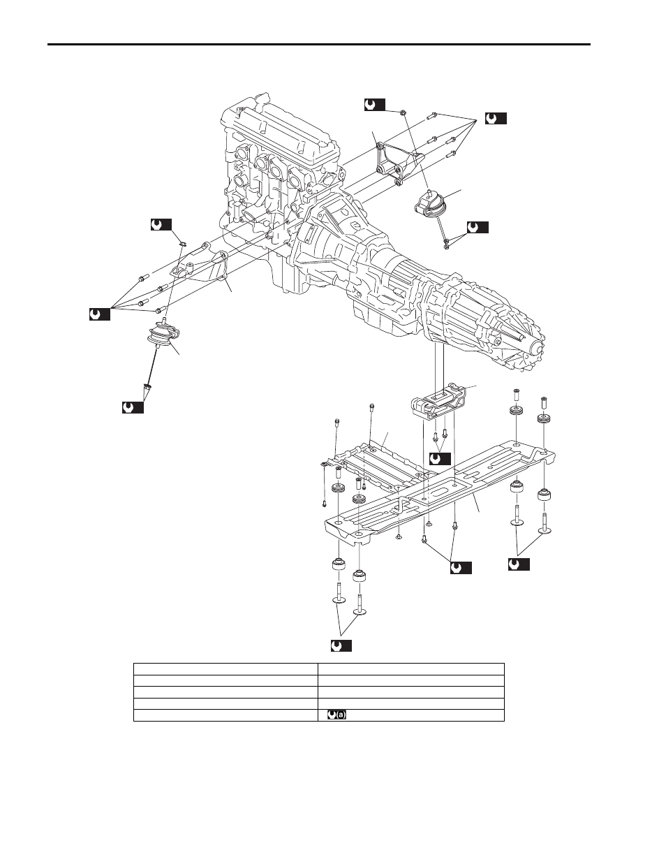
Engine Mountings Components
S5JB0A1426043
(a)
9
(a)
7
(a)
7
(a)
(a)
9
(a)
1
2
1
3
5
6
(a)
(a)
(a)
8
(a)
8
4
I5JB0A142016-01
1. Engine front mounting
6. Engine splash cover
2. Engine front mounting right bracket
7. Engine front mounting nut
3. Engine front mounting left bracket
8. Engine rear mounting member bolt
4. Engine rear mounting member
9. Engine front mounting bracket bolt
5. Engine rear mounting
: 55 N
⋅m (5.5 kgf-m, 40.0 lb-ft)