Suzuki Grand Vitara JB416 / JB420. Manual - part 104


  Index      Suzuki     Suzuki Grand Vitara JB416 / JB420- service repair manual


Search            


Content   ..  102  103  104  105   ..


Suzuki Grand Vitara JB416 / JB420. Manual - part 104


1D-84 Engine Mechanical: For J20 Engine

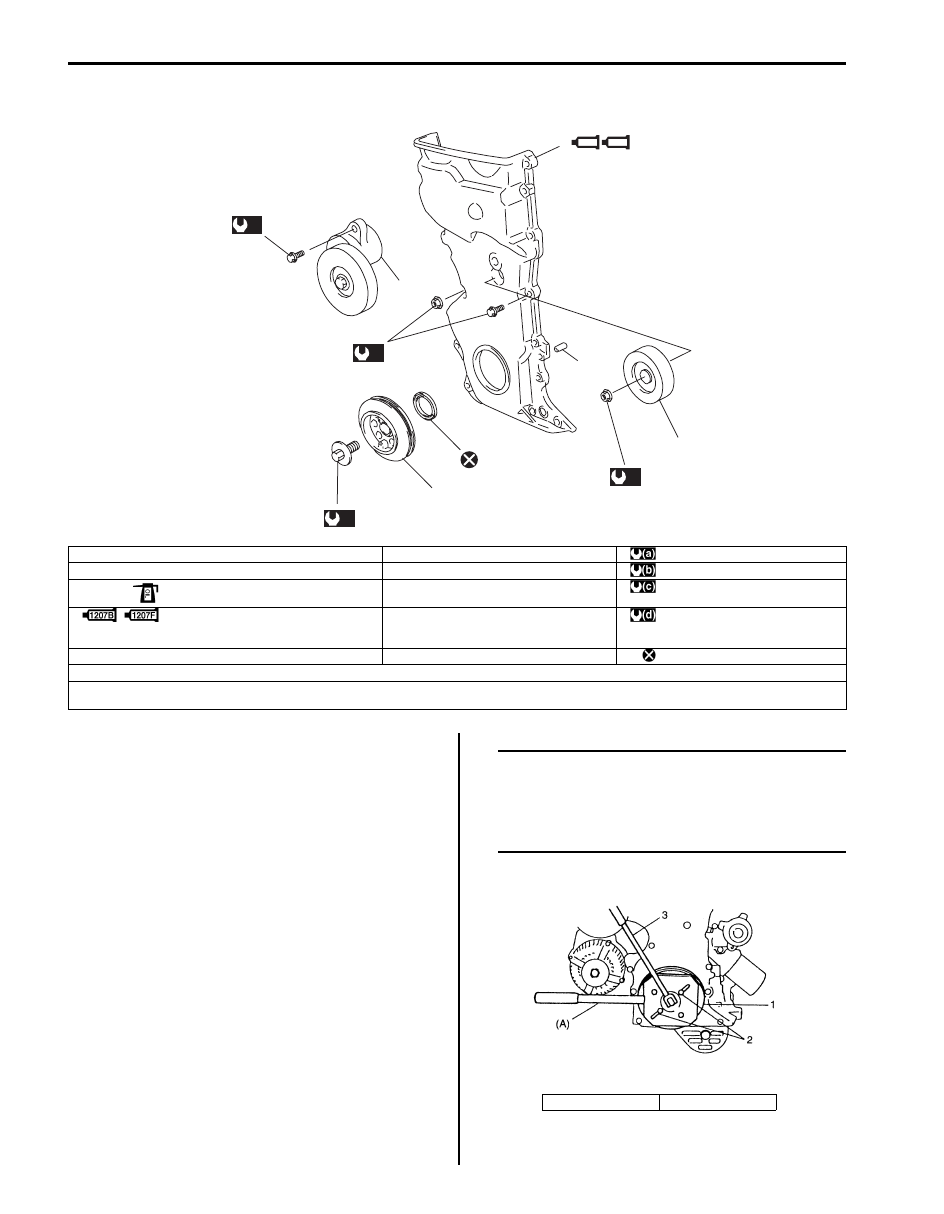
Timing Chain Cover Components

S5JB0A1426020

Timing Chain Cover Removal and Installation

S5JB0A1426021

Removal

1) Remove engine assembly from vehicle referring to 

“Engine Assembly Removal and Installation: For J20 
Engine”.

2) Remove oil pan referring to “Oil Pan and Oil Pump 

Strainer Removal and Installation: For J20 Engine in 
Section 1E”
.

3) Remove cylinder head cover referring to “Cylinder 

Head Cover Removal and Installation: For J20 
Engine”.

4) Remove crankshaft pulley bolt.

To lock crankshaft pulley (1), use special tool 
(camshaft pulley holder) as shown in figure.

Special tool
(a):  09917–68221

NOTE
Be sure to use the following bolts instead of 
pins in order to fix crankshaft pulley by 
special tool.
Bolt size: M8, P1.25 L = 25 mm (0.98 in.)
Strength: 7T


2

9

(d)

6

(b)

3

5

1207B

1207F

4

1

(a)

7

8

10

(c)

I5JB0A142021-01

1. Crankshaft pulley bolt

6. Timing chain cover bolt and nut

: 150 N

⋅m (15.0 kgf-m, 108.5 lb-ft)

2. Crankshaft pulley

7. Idler pulley

: 11 N

⋅m (1.1 kgf-m, 8.0 lb-ft)

 3. Oil seal

: Apply engine oil to oil seal lip.

8. Idler pulley nut

: 42 N

⋅m (4.2 kgf-m, 30.5 lb-ft)

 4. Timing chain cover

: See “A”
: See “B”

9. Generator belt tensioner bolt

: 25 N

⋅m (2.5 kgf-m, 18.0 lb-ft)

5. Belt tensioner

10. Pin

: Do not reuse.

“A”: Apply sealant 99000-31140 to the mating surface of cylinder and cylinder head.
“B”: Apply sealant 99000-31250 to the mating surface of timing chain cover referring to the figure of Step 3) in “Timing Chain Cover Removal and 

Installation: For J20 Engine”.

2. Bolt

3. Wrench

I2RH01140051-01

Engine Mechanical: For J20 Engine 1D-85

5) Remove crankshaft pulley (1).

To remove crankshaft pulley, use special tools 
(Steering wheel remover, Bearing puller attachment) 
with it as shown in figure.

Special tool
(A):  09944–36011
(B):  09926–58010

6) Remove idler pulley (1), water pump pulley (2) and 

belt tensioner (3).

7) Remove timing chain cover (1) bolts (3) and nut (2).

Installation

1) Clean sealing surfaces on timing chain cover, 

cylinder block and cylinder head.
Remove oil, oil sealant and dust from sealing 
surface.

2) Install new oil seal (2) to timing chain cover using 

special tool, if removed.

NOTE
When installing new oil seal (2), drive it until 
its surface is flash with edge of timing chain 
cover (1).


Special tool
(A):  09913–75510

I2RH01140052-01

I2RH01140054-01

I2RH01140055-01

I2RH01140061-01

1D-86 Engine Mechanical: For J20 Engine

3) Apply sealant “A” and “B” to specific area as shown 

in figure.

“A”:  Water tight sealant 99000–31250 (SUZUKI 
Bond No.1207F) 
“B”:  Water tight sealant 99000–31140 (SUZUKI 
Bond No.1207B) 

Sealant amount for timing chain cover
“a”: 3 mm (0.12 in.)
“b”: 2 mm (0.08 in.)
“c”: 6 mm (0.24 in.)
“d”: 16 mm (0.63 in.)
“e”: 14 mm (0.55 in.)
“f”: 65 mm (2.56 in.)
“g”: 73 mm (2.87 in.)
“h”: 4 mm (0.16 in.)

4) Apply engine oil to oil seal lip, then install timing 

chain cover (1). Tighten bolts and nut to specified 
torque.

NOTE
Before installing timing chain cover, check 
that pin is securely fitted.


Tightening torque
Timing chain cover bolt and nut (a):  11 N·m (1.1 
kgf-m, 8.0 lb-ft)

5) Install belt idler pulley (1). Tighten nut to specified 

torque.

Tightening torque
Idler pulley nut (a):  42 N·m (4.2 kgf-m, 30.5 lb-ft)

6) Install belt tensioner (2). Tighten bolts to specified 

torque.

Tightening torque
Generator belt tensioner bolt (b):  25 N·m (2.5 
kgf-m, 18.5 lb-ft)

7) Install water pump pulley (3).

8) Install cylinder head cover referring to “Cylinder 

Head Cover Removal and Installation: For J20 
Engine”.

9) Install oil pan. Refer to “Oil Pan and Oil Pump 

Strainer Removal and Installation: For J20 Engine in 
Section 1E”
 for installation.

10) Install crankshaft pulley. To lock crankshaft pulley 

(1), use special tool (camshaft pulley holder) as 
shown in figure.

Special tool
(A):  09917–68221

2. Cylinder head

5. Rub into

3. Cylinder head gasket

6. Jig

4. Cylinder block

[C]: View C

I5JB0A142022-03

I2RH01140057-01

I2RH01140058-01

Engine Mechanical: For J20 Engine 1D-87

NOTE
Be sure to use the following bolts instead of 
pins in order to fix crank pulley by special 
tool.
Bolt size: M8, P1.25 L = 25 mm (0.98 in.)
Strength: 7T


Tightening torque
Crankshaft pulley bolt (a):  150 N·m (15.0 kgf-m, 
108.5 lb-ft)

11) Install engine assembly to vehicle referring to 

“Engine Assembly Removal and Installation: For J20 
Engine”.

Timing Chain Cover Cleaning and Inspection

S5JB0A1426022

Clean
Clean sealing surface on timing chain cover, crank case, 
cylinder block and cylinder head.
Remove oil, old sealant, and dust from sealing surface.

Inspection
Check oil seal lip for fault or other damage. Replace as 
necessary.

2nd Timing Chain and Chain Tensioner Components

S5JB0A1426023

2. Bolt

3. Wrench

I2RH01140060-01

10

4

9

5

1

9

OIL

2

OIL

3

8

(a)

7

(c)

6

(b)

I5JB0A142023-02

 1. 2nd timing chain

: Apply engine oil

6. Camshaft timing sprocket bolt

: 11 N

⋅m (1.1 kgf-m, 8.0 lb-ft)

 2. Timing chain tensioner adjuster No.2

: Apply engine oil to sliding surface.

7. Timing chain tensioner adjuster No.2 nut

: 80 N

⋅m (8.0 kgf-m, 58.0 lb-ft)

3. Tensioner adjuster No.2 gasket

8. Timing chain tensioner adjuster No.2 bolt

: 45 N

⋅m (4.5 kgf-m, 32.5 lb-ft)

4. Intake camshaft timing sprocket

9. Pin

: Do not reuse.

5. Exhaust camshaft timing sprocket

10. Oil relief valve


Content   ..  102  103  104  105   ..