Suzuki Grand Vitara JB416 / JB420. Manual - part 101


  Index      Suzuki     Suzuki Grand Vitara JB416 / JB420- service repair manual


Search            


Content   ..  99  100  101  102   ..


Suzuki Grand Vitara JB416 / JB420. Manual - part 101


1D-72 Engine Mechanical: For J20 Engine

Valve Lash (Clearance) Inspection

S5JB0A1424003

1) Remove negative cable at battery.
2) Remove cylinder head cover referring to “Cylinder 

Head Cover Removal and Installation: For J20 
Engine”.

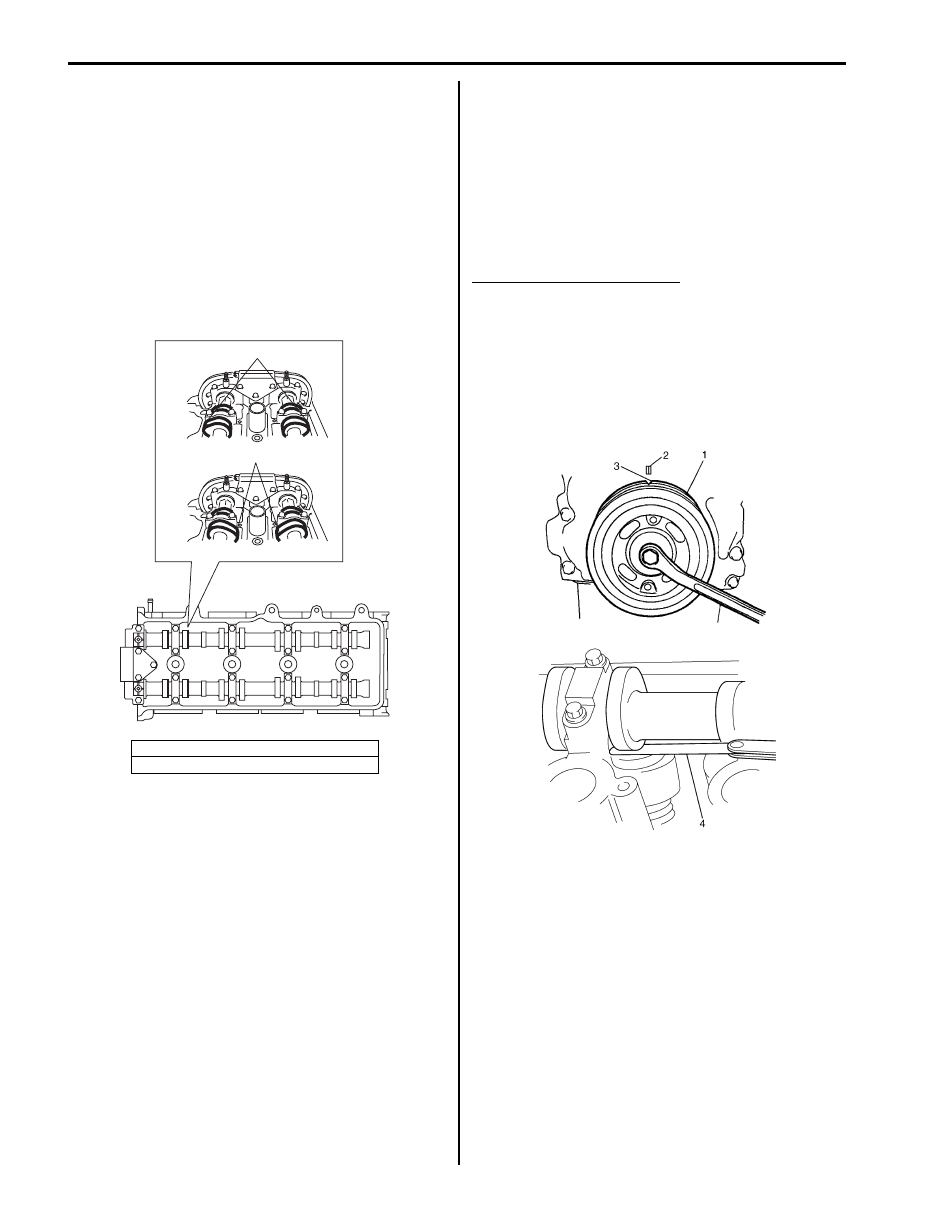
3) Using 17 mm wrench, turn crankshaft pulley (1) 

clockwise until index (2) of cylinder block and index 
(3) of crankshaft pulley (1) are aligned.

4) Check whether cam position (1) of No.1 cylinder is at 

the specified position [A] as shown in figure.
If cam position is [B], locate cam position to [A] by 
turning crankshaft one rotation.

5) Check valve lashes with thickness gauge (4) 

according to the following procedure.
a) Check valve lashes of cylinder No.1.
b) Turn crankshaft pulley by 180

° clockwise.

c) Check valve lashes of cylinder No.3.
d) In the same manner as b) – c), check valve 

lashes of cylinder No.4 then cylinder No.3.

If valve lash is out of specification, record valve lash and 
adjust it to specification by replacing shim.

Valve clearance specification
When cold (Coolant temperature is 15 – 25 

°C (59 – 

77 

°F)):

• Intake: 0.18 – 0.22 mm (0.007 – 0.009 in.)
• Exhaust: 0.28 – 0.32 mm (0.011 – 0.013 in.) 

When hot (Coolant temperature is 60 – 68 

°C (140 – 

154 

°F)):

• Intake: 0.21 – 0.27 mm (0.008 – 0.011 in.) 
• Exhaust: 0.30 – 0.36 mm (0.012 – 0.014 in.)

[A]: TDC in compression for No.1 cylinder
[B]: TDC in exhaust for No.1 cylinder

[A]

[B]

1

1

I5JB0A142064-01

I5JB0A142065-01

Engine Mechanical: For J20 Engine 1D-73

Replacement of Shim

1) Close the valve whose shim (2) is to be replaced by 

turning crankshaft, then turn tappet (3) till its cut 
section (1) faces inside as shown in the figure.

2) Lift down the valve by turning crankshaft to 360

°.

3) Hold tappet at that position using special tool as 

follows.
a) Remove its housing bolts.
b) Check housing No. and select special tool 

corresponding to housing No., referring to 
“Special tool selection table”.

Special tool selection table

c) Hold down the tappet so as not to contact the 

shim by installing special tool on camshaft 
housing with housing bolt (1) tighten housing 
bolts to specified torque.

Special tool
(A):  09916–66510

Tightening torque
Camshaft housing bolts (a):  11 N

m (1.1 kgf-

m, 8.0 lb-ft) for tightening of special tool

4) Turn camshaft by approximately 90

° clockwise and 

remove shim (3).

WARNING

!


Never put in the hand between camshaft and 
tappet.


No. on camshaft 

housing

Embossed mark on 

special tool

I2, I3, I4, I5

IN

E2, E3, E4, E5

EX

A: I: Intake side or E: Exhaust side
B: Position from timing chain side

C: Pointing to timing chain side

I2RH0B140006-01

I5JB0A142066-01

1. Special tool

2. Magnet

I3RM0A140005-01

I2RH0B140013-01

1D-74 Engine Mechanical: For J20 Engine

5) Using a micrometer (2), measure the thickness of 

the removed shim (1), and determine replacement 
shim by calculating the thickness of new shim with 
the following formula and table.

Shim thickness specification
Intake side:
A = B + C – 0.20 mm (0.008 in.)
Exhaust side:
A = B + C – 0.30 mm (0.012 in.)
A: Thickness of new shim
B: Thickness of removed shim
C: Measured valve clearance

For example of intake side:
When thickness of removed shim is 2.40 mm (0.094 
in.), and measured valve clearance is 0.45 mm 
(0.018 in.).
A = 2.40 mm (0.094 in.) + 0.45 mm (0.018 in.) – 0.20 
mm (0.008 in.) = 2.65 mm (0.104 in.) 
Calculated thickness of new shim = 2.65 mm (0.104 
in.)

6) Select new shim No. (1) with a thickness as close as 

possible to calculated value.

Available new shims No.

7) Install new shim facing shim No. side with tappet.

8) Lift valve by turning crankshaft counterclockwise (in 

opposite direction against above Step 4)) and 
remove special tool.

Special tool
(A):  09916–66510

9) Install camshaft housing (1) and tighten bolts to 

specified torque.

Tightening torque
Camshaft housing bolt (a):  11 N·m (1.1 kgf-m, 
8.0 lb-ft)

10) Turn crankshaft pulley more than 4 rotations.

11) Check valve clearance again after adjusting it.

12) After checking and adjusting all valves.
13) Install cylinder head cover referring to “Cylinder 

Head Cover Removal and Installation: For J20 
Engine”.

Thickness 

mm (in.)

Shim No.

Thickness 

mm (in.)

Shim No.

2.175 (0.0856)

218

2.600 (0.1024)

260

2.200 (0.0866)

220

2.625 (0.1033)

263

2.225 (0.0876)

223

2.650 (0.1043)

265

2.250 (0.0886)

225

2.675 (0.1053)

268

2.275 (0.0896)

228

2.700 (0.1063)

270

2.300 (0.0906)

230

2.725 (0.1073)

273

2.325 (0.0915)

233

2.750 (0.1083)

275

2.350 (0.0925)

235

2.775 (0.1093)

278

2.375 (0.0935)

238

2.800 (0.1102)

280

2.400 (0.0945)

240

2.825 (0.1112)

283

2.425 (0.0955)

243

2.850 (0.1122)

285

2.450 (0.0965)

245

2.875 (0.1132)

288

2.475 (0.0974)

248

2.900 (0.1142)

290

2.500 (0.0984)

250

2.925 (0.1152)

293

2.525 (0.0994)

253

2.950 (0.1161)

295

2.550 (0.1004)

255

2.975 (0.1171)

298

2.575 (0.1014)

258

3.000 (0.1181)

300

I2RH0B140014-01

1. Tappet

2. Camshaft

I2RH0B140015-01

(A)

2

1

I3RM0A140006-01

I2RH0B140149-01

Engine Mechanical: For J20 Engine 1D-75

Repair Instructions

Air Cleaner Assembly Removal and Installation

S5JB0A1426044

Removal

1) Disconnect breather hose (1) from air cleaner outlet 

hose (2).

2) Remove air cleaner outlet hose (2).
3) Disconnect MAF sensor connector (3).
4) Remove air cleaner case (4).

Installation

1) Install air cleaner case (4).
2) Connect MAF sensor connector (3).
3) Install air cleaner outlet hose (2).
4) Connect breather hose (1) to air cleaner outlet hose 

(2).

Air Cleaner Filter Removal and Installation

S5JB0A1426002

Removal

1) Remove air cleaner upper case (1) from lower case 

after hooking clamps (2) from upper case.

2) Remove air cleaner filter.

Installation
Reverse removal procedure for installation.

Air Cleaner Filter Inspection and Cleaning

S5JB0A1426003

Inspection
Check air cleaner filter for dirt.

Cleaning
Blow off dust by compressed air from air outlet side of 
element.

3

2

1

4

I5JB0A142003-01

3

2

1

4

I5JB0A142003-01

2

1

I5JB0A142004-01

I2RH01140007-01


Content   ..  99  100  101  102   ..