Dacia SuperNova (engine E7J). Manual - part 138


  Index      Dacia     Dacia SuperNova (engine E7J) - service repair manual 2004 year


Search            


Content   ..  136  137  138  139   ..


Dacia SuperNova (engine E7J). Manual - part 138


87

ELECTRICAL ASSISANCE EQUIPEMENT

WINDSCREEN WASHING ASSEMBLY

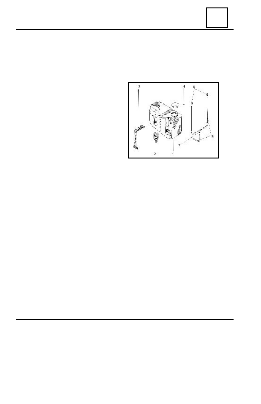
It is located in the left part of the climate control box, being attached with an attachment strap (3)

and the windscreen washing electric pump (2) is attached on the reservoir (1) by means of clips.

In the drawing, the following elements may be identified:

1. Windscreen washing reservoir.
2. Electric pump
3. Attachment strap
4. Sustaining clip
5. Piping
6. Nozzles
7. T connector

DISMOUNTING

Disconnect the battery;
Disconnect the electric connectors from the electric pump.
Disconnect the pipe connected to the electric pump.
Dismount the washing reservoir, releasing the attachment strap.

REMOUNTING

Perform the dismounting operations in reverse order.
Check the nozzles adjustment, in order to obtain correct windscreen washing.

87 - 1

WINDSCREEN WASHING

89A

ELECTRICAL DIAGRAMS

89A - 1

GENERALITIES

GENERAL PRESENTATION

From the electric point of view, the electric diagrams of the vehicle have been structured as

Applied Principle Schemes (APS), which are presented according to the function each system of
the vehicle is having, from electric point of view. These APS diagrams also contain detail concerning
the internal function of some simple electric components (contacts, relays), thus contributing to a
better understanding of the system functioning and of the incident correct diagnosis.

The list of the functional diagrams is presented in chapter 3, where the vehicle Applied Principle

Schemes may be found. These are divided in: electric supply diagrams, mass connection diagrams
and system functional diagrams.

The electric functional diagrams (APS), are presented in chapter 8 and on these, the following

may be identified:

- electric components, marked by a 3-4 figures; their identification on the electric diagrams

can be achieved by means of “index of components” – Chapter 4;

- couplings between the electric wires, marked by the letter R followed by figures; they are

indicated in  the  Chapter 5  list;

- mass connections, marked by the letter M followed by a figure or a letter, are indicated

in Chapter 5.

Each wire of the electric diagrams is marked by an alphanumeric code, representing the wire

function, followed by  figures representing the wire sectioning.

The connectors and couplings between the wires are presented in chapter 12, where they are

drawn from the wires inlet to the connector/coupling. The wires entering each connector socket
are identified by means of the above-mentioned drawings. The Chapter 11 also includes tables
with details about each wire entering the connector: wire location in the connector socket, wire
sectioning, wire function code and its destination.

Abbreviation index- in chapter 2, the abbreviations used in the tables of chapter 12, are

detailed explained.

Chapter 11  includes the index of wire functions in connectors and couplings, representing the

list of all the connectors and couplings and helping to their easy identification in Chapter 12.

The mass and coupling position on the vehicle is presented in chapter 6 and helps to identify

the electric mass fixing points on it and the location of the couplings between its wires.

The electric components position on the vehicle is presented in chapter 7. The position of the

various components with electric functions on the vehicle can be identified by means of the
components list.

The cockpit fuse box is presented in chapter 9 and contains information about its positioning,

the functional purpose of the fuse and their relays and the description of the wiring connectors
connected to  this  one.

89A

ELECTRICAL DIAGRAMS

89A - 2

The fuse box from the engine compartment is presented in chapter 10, that contains information

about its positioning on the vehicle and the functional purpose of the relays and fuse placed on it.

The functional codes of the wires are detailed explained in chapter 13.

FUNCTIONAL DIAGRAMS INTERPRETATIONS

The functional diagrams information included in Chapter 8 are to be interpreted taking into

consideration the explanation referring to the following example:

1 = vehicle class
2 = manufacturing year
3 = electric functional diagram denomination
4 = criteria of equipment differentiation for identifying the functional diagram
5 = electric connector colour*
6 = connector graphical representation
7 = electric component index number
8 = fuses box number where the relay or the safety fuse are mounted.
9 = identification of the safety fuse on the fuses box

10 = safety fuse value

11 = identification of wiring joints

12 = electric mass identification
13 = electric connection colour between wires*
14 = electric connection identification
15 = electric connection graphical representation
16 = symbol (sign) pages containing functional diagrams
17 = wire function code
18 = wire sectioning
19 = functional diagram number

The electric connectors (5) and the couplings (13) are symbolised by the following colours:

BA = white

GR = grey

RG =  red

NO = black

MA= brown

CY = white

BE = blue

VE = green

GENERALITIES

89A

ELECTRICAL DIAGRAMS

89A - 3

BLOWER COOLING

GENERALITIES


Content   ..  136  137  138  139   ..