Dacia SuperNova (engine E7J). Manual - part 133


  Index      Dacia     Dacia SuperNova (engine E7J) - service repair manual 2004 year


Search            


Content   ..  131  132  133  134   ..


Dacia SuperNova (engine E7J). Manual - part 133


84

CONTROLS - SIGNALLING

84 -1

(STARTING – IGNITION SWITCH)

The anti theft mechanism is placed on the right part of the steering column and has the purpose

to starter control when electric system is connected, being provided in the same time also with a
steering locking device, with anti theft lock.

NOTE
At the anti  theft mechanism there is not any more marked G position (garage) because

it does not allow the taking out of the key in this position but helps in pin unblocking
for removing the mechanism from the steering column.

Disconnect the battery.
Dismount the steering wheel casings.
Disconnect the anti-starting  bushing.
Remove the bushing off the steering column.
Disconnect the switch connection wires.
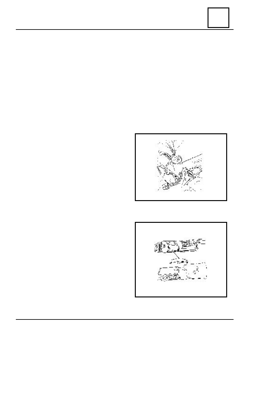
Bring the key in the intermediary position (ex G).
Dismount the attachment screw (1).
Push the mobile  pin (2) and pull backwards

the switch.

REMOUNTING

Mount the switch in its place.
Tighten the attachment screw(1).
Connect :

- the switch
- the battery.

Position and mount the anti-starting bushing.
Connect the anti-starting bushing to the ve-

hicle wiring.

Check the switch operation.
Mount the steering wheel casings.

DISMOUNTING

ANTI THEFT MECHANISM

84

CONTROLS - SIGNALLING

84-2

CONNECTING PLUGS REPLACEMENT

The operations are to be performed after dismounting the contact switch from the vehicle.

Dismount the attachment screws of the

blocking wedge guiding.

Dismount the connecting plugs.

Position and mount the connecting plugs.
Mount the blocking wedge guiding
Tighten the attachment screws of the blocking wedge guiding.

DISMOUNTING-REMOUNTING THE FIX AND MOBILE

HATCHBACK CONTACT (until 01.06.2001)

FIX CONTACT

DISMOUNTING
Disconnect the battery.
Disconnect the connections boxes from

the rear wiring.

Dismount the attachment screw(2) of the

guiding body.

MOBILE CONTACT

DISMOUNTING
Dismount the contact attachment screw (1) on the hatchback.
Dismount the attachment screws of the obturator cap on the hatchback.
Disconnect the mobile contact connectors from the consumers (license plate  lamps, STOP-

S3 lamp, rear window defrosting).

Extract the mobile contact and its wiring.

REMOUNTING
Perform the dismounting operations in the reverse order, previously checking the contacts

base pins sliding.

DISMOUNTING

REMOUNTING

Extract by detaching from clips the fix contact from the guiding body.

REMOUNTING
Perform the dismounting operations in  the reverse order.

ANTI THEFT MECHANISM

84

CONTROLS - SIGNALLING

84-3

SIGNALIZING AND LIGHTING CONTROL SWITCH

DISMOUNTING-REMOUNTING

The lighting control switch equipping the SupeRNova vehicles includes also the turning-

signalizing switch.

NOTE
The lighting control switch is not to be repaired.

DISMOUNTING

Disconnect the battery.
Dismount the lower steering wheel casing.
Cut the plastic collar which is attaching the wiring on the steering column.
Disconnect the switch connector from the front wiring.
Dismount the switch attachment screw from the steering column.
Dismount the switch.

REMOUNTING

Tighten the switch attachment screws.
Connect the switch connector to the front wiring.
Position the plugs and fix with a new plastic collar.
Connect the battery.
Check the switch operation.
Mount the steering wheel lower casing.

UNDER WHEEL CONTROL MODULE

84

CONTROLS - SIGNALLING

84-4

DISMOUNTING-REMOUNTING OF THE WINDSCREEN

WIPER-WASHING SWITCH

DISMOUNTING

Disconnect the battery.
Dismount the steering wheel casings.
Disconnect the switch connector.
Dismount the windscreen wiper switch attachment screws (2).
Detach the  switch.

REMOUNTING

Fix the switch by tightening its attachment screws (2).
Connect the switch connector to the front wiring.
Mount the steering wheels casings.
Connect the battery.
Check the switch operation.

The SupeRNova vehicles are equipped with TAKOSAN type switches.

2

1

UNDER WHEEL CONTROL MODULE


Content   ..  131  132  133  134   ..