Dacia SuperNova (engine E7J). Manual - part 69
31
FRONT BEARING ELEMENTS
31 - 17
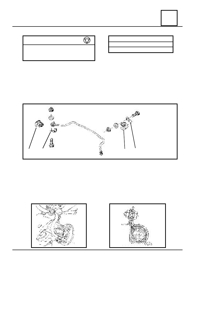
ANTI-ROLL BAR
DISMOUNTING
Unscrew :
- the screws of the elastic bushings attachment clamps on longitudinal girders;
- the attachment clamps screws on arm.
Dismount the anti-roll bar.
Check the state of the elastic bushings and bushings.
Replace them if necessary.
REMOUNTING
Mount the bushings and anti-roll bar attachment elastic bushings.
Mount the anti-roll bar.
Press the front axle at half load.
Tighten at the required moment, the screws of bushing attachment clamps on the arm and
those of the elastic bushings attachment on longitudinal girder ( the mounting position of the
elastic bushings shall be with the slot (A) towards the clamp attachment screw on frame).
TIGHTENING MO
MENTS (daNm)
Screws for attaching the elastic bushings
clamps on longitudinal girder
2,5
Clamps screws for attaching bushings on arm2,5
FRONT ANTI-ROLL BAR
Diameter (mm)
Φ
Φ
Φ
Φ 24
1
A
4
3
2
1
1. Bushing
2. Bushing attachment clamp
3.Elastic bushing attachment
clamp
4. Elastic bushing