Dacia SuperNova (engine E7J). Manual - part 67
31
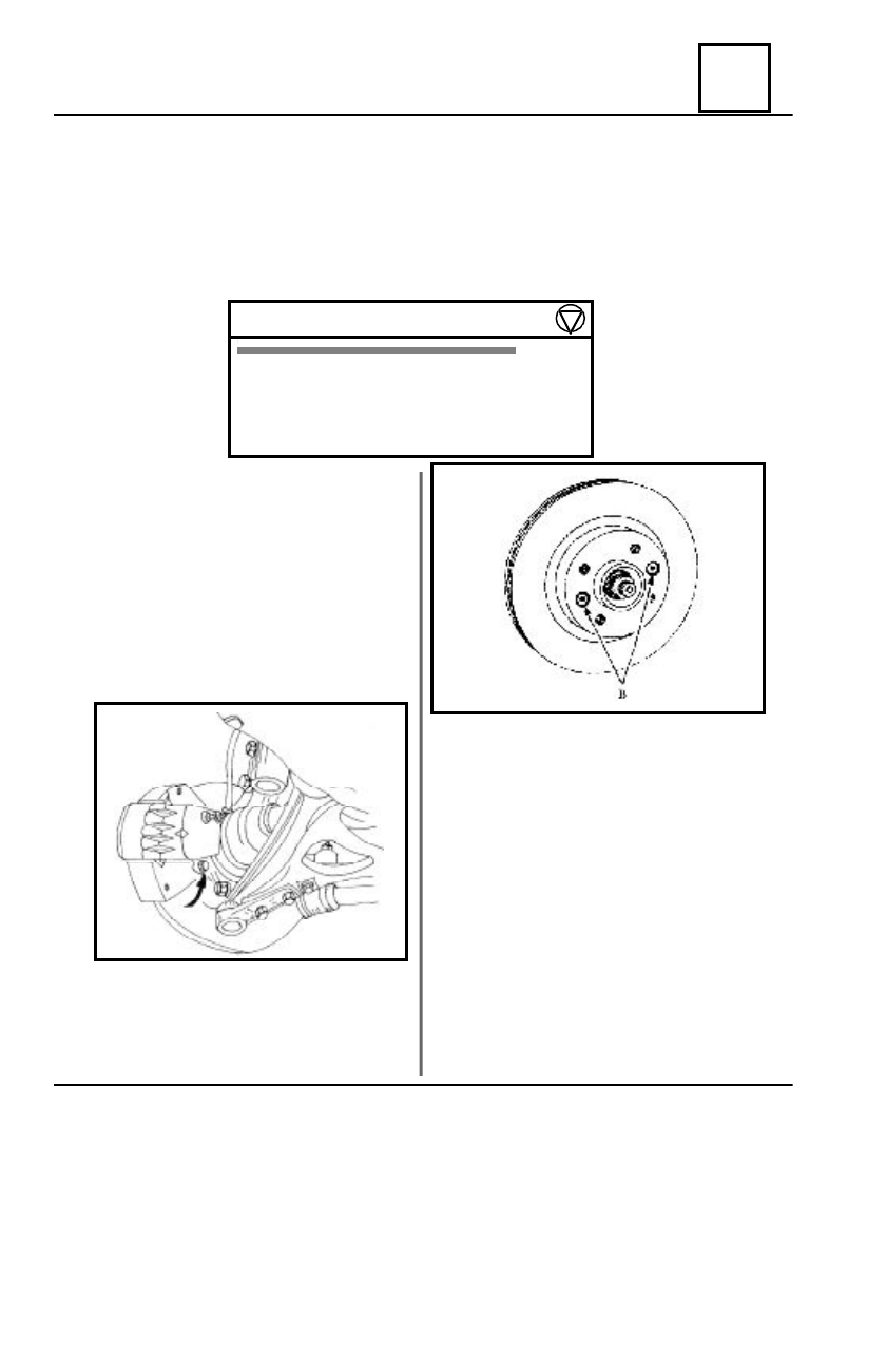
FRONT BEARING ELEMENTS
31 - 9
DISMOUNTING
Lift the vehicle by means of a two col-
umns elevator.
Dismount :
- the wheel;
- the two attachment screws M 12 ( B)
of the brake disk assembly on the steering knuckle;
- the brake pads;
- the two sunk screws attaching the
disk on the hub.
BRAKE DISK
The brake disks can be not rectified.
A bigger wear or an important mark on the brake disk braking surfaces impose obligatory its
replacement.
- The minimal accepted thickness : 19 mm
- The maximum accepted axial deviation 0,1 mm on a diameter of F 215.
TIGHTENING MOMENTS (daNm)
steering nuckle
6,5
Disk attachment screw on the hub
2,5
Front wheel steering knuckle nut 21
Wheel screws
7,5
Before remounting, check:
- the wear of the flexible hose;
- the wear of the brake pads and
replace them if necessary.
REMOUNTING
Remount :
- the disk on the hub by means of the two
sunk screws M8 and tighten them to the required
moment;
- the brake disk assembly on the steering
knuckle, tightening the M 12 screws at the
required moment.
Press the brake pedal several times, in order
to bring the piston in contact with the brake pads.
NOTE :
In case of replacing the brake disk it is ab-
solutely necessary to replace the brake pads.