Dacia Solenza (engine E7J). Manual - part 116


  Index      Dacia     Dacia Solenza (engine E7J) - service repair manual 2004 year


Search            


Content   ..  114  115  116  117   ..


Dacia Solenza (engine E7J). Manual - part 116


61

HEATING

61 - 2

Operating principle

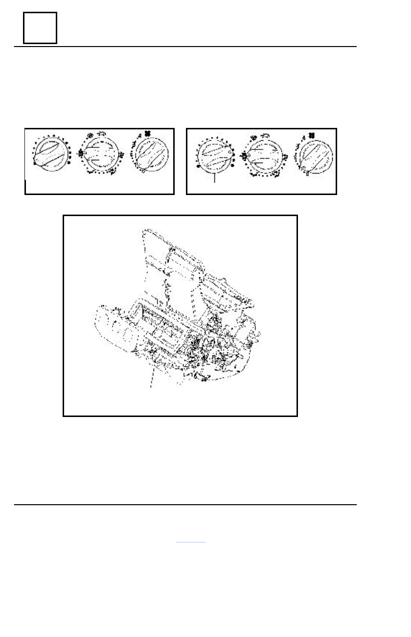
AIR TEMPERATURE CONTROL

The knob (A) is controlling the flaps for cold/warm air.
By rotating to the right the (A) knob, the air temperature is increasing.

Cold air

Warm air

The heating radiator is not having any valve and is permanently supplied. The flap controlled

by the cable (1) is ensuring the operation of the cold air re-heating system.

A

A

1

61

HEATING

61 - 3

AIR REPARTITION CONTROL

The knob (B) is controlling air repartition flaps

(1).

Position
Airflow is directed towards the dashboard

side air  vents.

Each air vent has three adjustments:

- open or closed;
- upward or downward directed
- left or right directed

Position
Airflow is directed towards all dashboard air

vents and towards passengers legs.

Position
Airflow is directed towards passengers legs.

Operating principle

Position
Airflow is distributed between all air vents,

defogging air vents of front side windows,
windscreen defogging air vent and passengers
legs.

Position
For a better efficiency, the dashboard air

vents are to be closed.

The whole airflow is directed towards de-

fogging strip and air vents of the front side win-
dows.

Position
Entire cockpit is outside isolated and out-

side air penetration is not allowed, climate con-
trol blower operation being stopped.

AIR QUANTITY CONTROL
The airflow rate cycled in the cockpit is

settled by the (C) knob position, corresponding
to the four speeds of the climate control blower.
The more speed step is bigger the more airflow
is bigger.

REMARK

   For a better efficiency of the windscreen
defrosting or defogging, the (C) knob must
be placed on the last position.

In order to stop the climate control blower

operation, rotate the knob on “0” position.

B

1

B

C

61

HEATING

61 - 4

Climate control unit

DISMOUNTING

Disconnect the battery.
Dismount :

- climate control box protector;
- climate control box gasket
- gas purge vessel;
- engine air filter.

Detach from clips the front wiring from the

central part of the climate control box.

Dismount, then:

- attachment screws of the climate con-

trol unit on the climate control box.

- attachment screws of the central part

of the climate control box.

Disconnect and release the climate control

unit from the climate control box.

REMOUNTING

Perform the dismounting operations in  the

reverse order.

Tighten the attachment  screws  of  the cli-

mate control unit on the climate control box, in
the sequence shown in drawing (1,2,3 ).

The required tightening moment of the at-

tachment screws of  climate control unit on the
climate control box is of  0,6 daNm.

Connector

2

3

1

Pin

Denomination

3

Blower control speed 1

4

Blower control speed 2

5

Blower control speed 3

12

Blower control speed 4

13

Blower control speed 4

14

Mass

15

Mass

15

12

5

3

61

HEATING

61 - 5

1

2

3

Ventilation-climate control air distributor (RACV)

DISMOUNTING

Disconnect the battery.
Dismount :

- dashboard (see chapter 57 “dash-

board”);

- central console;
- electric windows control connectors;
- front pillars coverings;
- driving post cross beam;
- climate control box protector;
- gas purge vessel;
- climate control box gasket;
- engine air filter;
- climate control box central part from

the eight attachment screws;

- attachment screws of the climate con-

trol unit and release the climate control blower
after disconnecting it.

- RACV attachment screws (1)  on the

climate control box.

Clamp the two hoses from the heating ra-

diator by means of the MOT 453 device.

Disconnect then the fast couplings from the

RACV heating radiator, recovering the cool-
ing fluid.

Dismount then:

- acoustic plate (2);
- mixing and distribution flaps control

cables attached on RACV.

Release RACV (3).

REMOUNTING

Perform the dismounting operations in the

reverse order.

Fill up the cooling fluid and perform the cool-

ing circuit purging (see chapter 19 “ Filling –
Purging cooling circuit”).

 Check :

- good operation of the flaps cables;
- good attachment of the air ducts.

The required tightening moment of the

RACV attachment screws (1) on the climate
control box is of  0,6 daNm.


Content   ..  114  115  116  117   ..