Dacia Solenza (engine E7J). Manual - part 102
SIDE UPPER STRUCTURE
43
43 - 02
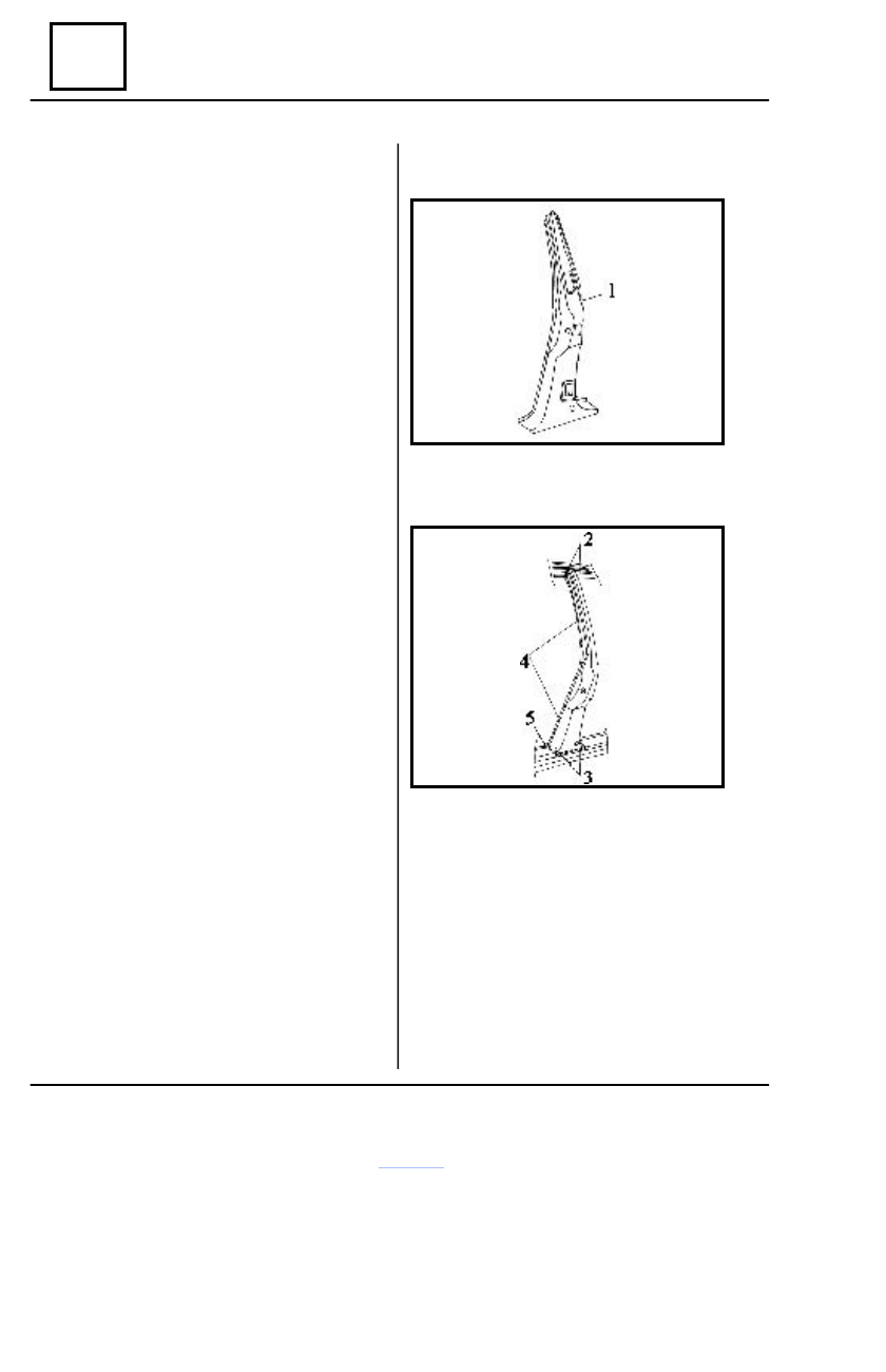
Middle pillar
DISMOUNTING
Dismount the elements, which are in contact
with the middle pillar.
Detach the welding points of the middle pillar
(1) which are in connection with :
- side frame lining in the areas (3) and (4);
- middle pillar reinforcement in the area (4);
- roof belt in the area (2);
- threshold closing plate in the area (5).
Straighten the areas resulted by dismounting.
Grind the areas resulted by dismounting.
REMOUNTING
Fit temporary the middle pillar (1) on the side
frame lining and clench it in 203 points.
Check the correct pillar positioning using the
door as geometric gauge.
Weld the middle pillar following the welding
outlines (2), (3) (4) and (5).
Perform a hardening gas protection welding
(SE CO
2
) in the areas (2) and (3) (2 + 2 weld
x 10 mm).
Attach the rear door observing the openings
clearance.
Weld the door hinges on the middle pillar
(electric weld under protection gas, with
continuos weld on all hinges sides).
Grind the performed welding.
Protect the performed welding with a corro-
sion-protection product.
Paint the affected area in the carriage body
color.
Mount the connection elements by performing
the dismounting operations in the reverse order.