Dacia Solenza (engine E7J). Manual - part 100


  Index      Dacia     Dacia Solenza (engine E7J) - service repair manual 2004 year


Search            


Content   ..  98  99  100  101   ..


Dacia Solenza (engine E7J). Manual - part 100


41

41 - 4

LOWER STRUCTURE

1

Rear longitudinal girder

REPLACEMENT

This operation shall be performed only on the repair/checking bench.. For the specific sup-

ports mounting on the bench, please see the 40 chapter.

 DISMOUNTIN

G

Dismount the damaged elements, which are

in contact with the rear longitudinal girder.

Proceed to a straightening on the body

checking/ straightening  until bringing the  ve-
hicle as closed as possible to the initial shape.

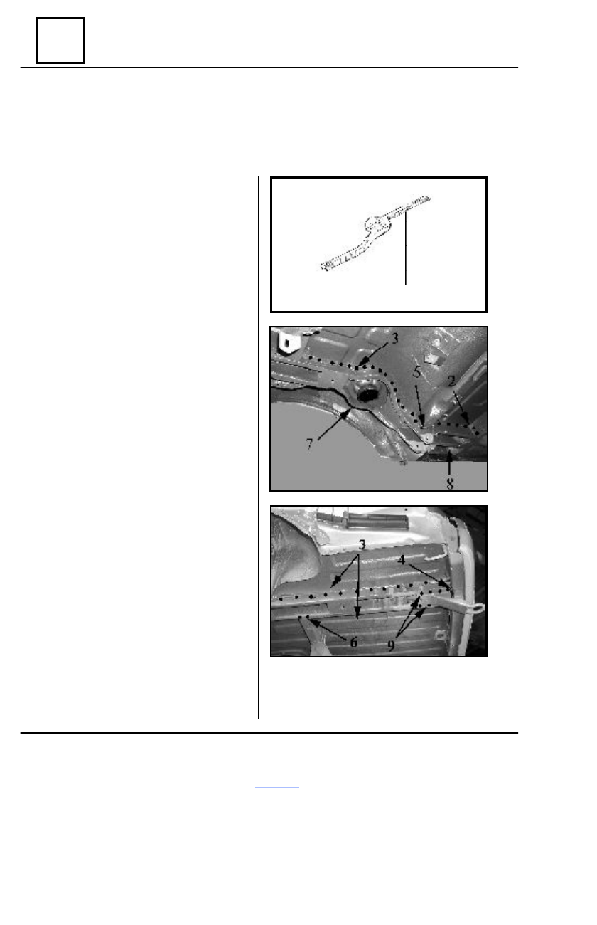
Detach the welding points of the rear

longitudinal girder (1), which are in contact
with:

- central floor in the area (2);
- rear floor in the area (3);
- rear extreme cross member in the area (4);
- tank front cross member in the area (5);
- tank rear cross member in the area (6);
- inner wheel passage in the area (7);
- rear towing hock in the area (9).

Detach the welding points between the  rear

side cross member, rear floor and threshold
closing plate in  the area  (8).

Straighten the areas resulted after dismounting.
Grind the areas resulted after dismounting.


REMOUNTING

Position and center the new element by

means of  the repairing  bench.

Weld the rear longitudinal girder following

the assembling outlines 2,3,4,5,6,7, 8 and
9
(spots and  under  gas protection welding)

Grind the performed welding.
Protect the  performed welding with an

anticorrosive product.

Protect the replaced element with a noise

absorbent product.

Mount the connection elements by

performing the dismounting operations in the
reverse order.

42

42 - 1

FRONT UPPER STRUCTURE

DISMOUNTING

Dismount the two attachment screws of the bonnet lower half-hinge on the front pillar lining.
Dismount partially the front bumper.
Dismount the attachment screws (1) of the wheel passage fairing.
Dismount the side-signaling lamp from the front wing.
Dismount the attachment screws (2)(3)(4) and (5) of the wing on the front wing lining, front

pillar lining, front bumper attachment side support, front pillars support and side frame lining
(front lower area).

Dismount the front wing.

REMOUNTING

Perform the dismounting operations in the reverse order, ensuring the sealing by applying a

sealant material layer in the connection area of the wing with the front wing lining, front pillar and
side frame lining.

Front wing

42

42 - 2

FRONT UPPER STRUCTURE

Front wing lining

2

4

5

6

7

8

3

REPLACEMENT

This operation shall be performed only on the checking/repair bench. For the specific sup-

ports mounting on the bench, please see the 40 sub-chapter.

  DISMOUNTING

Dismount the damaged elements, which are

in contact with the front wing lining.

Detach the welding points of the front wing

lining  (1), which are in contact with :

- upper longitudinal girder in (2) area;
- front cross member in the area (3);
- headlamp support  in  the area (4);
- closing plate  in the area (5) ;
- front floor in the area (6);
- cowl panel in the area (7);
- climate  control box in the area (8)

Straighten  the area resulted from

dismounting.

Grind the area resulted from dismounting.

REMOUNTING

Position and center the new element by

means of  the repairing  bench.

Weld the front wing lining (1) following the

assembling outlines  2, 3, 4, 5, 6, 7 and 8.

Protect the performed welding with a

corrosion-preventing product.

Protect the front wing lining with a noise

absorbent product and paint the affected area
in the carriage body color.

Mount the connection elements by perform-

ing the dismounting operations in the reverse
order.

1

42

42 - 3

FRONT UPPER STRUCTURE

Radiator upper cross member

2

1

3

5

4

DISMOUNTING

Dismount the elements, which are in con-

tact with the radiator upper cross member.

Detach the welding points of the radiator

upper cross member (1), which are in
connection with:

- front wing lining in the area (3);
- headlamp support in the area (4);
- side wall in the area (5);

Straighten the areas resulted by dismounting.
Grind the areas resulted by dismounting.

REMOUNTING

Position and center the new element.
Check the correct positioning of the radia-

tor upper cross member.

Weld the radiator upper cross member (1)

following the welding outlines (3), (4) and (5).

Protect the welds with a corrosion-

preventing product.

Mount the elements, which are in connection

with the radiator upper cross member, by
performing the dismounting operations in  the
reverse order.


Content   ..  98  99  100  101   ..