Nissan Altima L32. Manual - part 1524


  Index      Nissan     Nissan Altima L32 (2007-2009 year) - Service and Repair Manual


Search            


Content   ..  1522  1523  1524  1525   ..


Nissan Altima L32. Manual - part 1524


TM-440

< ON-VEHICLE REPAIR >

[CVT: RE0F10A]

CONTROL VALVE

CONTROL VALVE

Exploded View

INFOID:0000000004507226

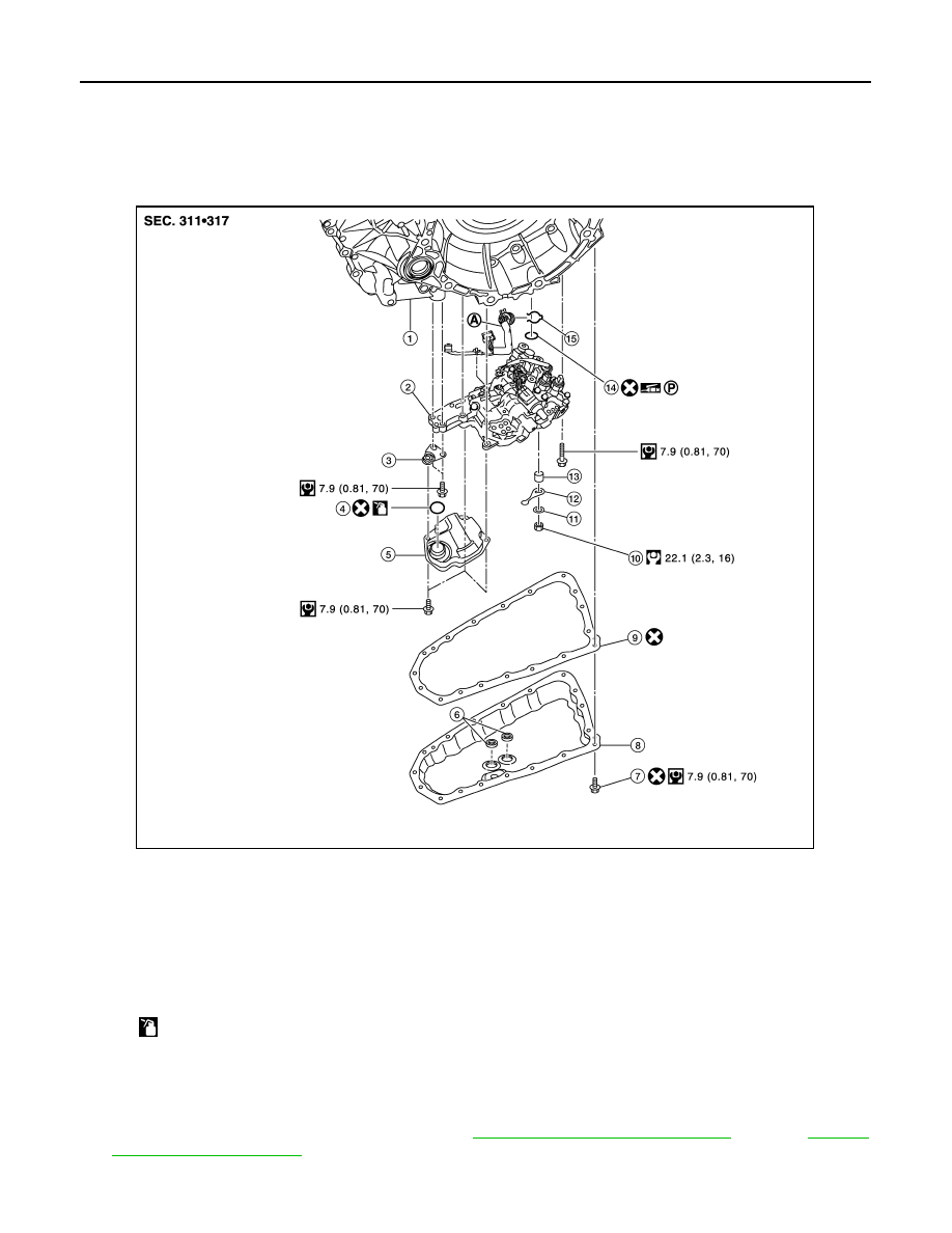
COMPONENT PARTS LOCATION

Removal and Installation

INFOID:0000000004507227

REMOVAL

1. Disconnect negative battery terminal. Refer to 

PG-68, "Removal and Installation"

 (coupe), 

PG-139,

"Removal and Installation"

 (sedan).

2. Pump out CVT fluid from CVT charging pipe.

1.

Transaxle assembly

2.

Control valve

3.

Bracket

4.

O-ring

5.

Oil strainer assembly

6.

Magnet

7.

Oil pan bolt

8.

Oil pan

9.

Oil pan gasket

10.

Lock nut

11. Washer

12. Manual plate

13.

Collar

14. Lip seal

15. Snap ring

A.

CVT unit connector

For the following symbols, use the specified fluid. 

NISSAN CVT Fluid NS-2

AWDIA0636GB

CONTROL VALVE

TM-441

< ON-VEHICLE REPAIR >

[CVT: RE0F10A]

C

E

F

G

H

I

J

K

L

M

A

B

TM

N

O

P

3. Disconnect the CVT unit connector. Refer to 

TM-411, "Removal and Installation Procedure for CVT Unit

Connector"

.

4. Remove the snap ring (1) from the CVT unit connector (A).

5. Press the CVT unit connector (A) into the transaxle case.

CAUTION:

Never damage the CVT unit connector.

NOTE:

Clean around the connector to prevent foreign materials from

entering into the transaxle case.

6. Remove the oil pan bolts, and then remove the oil pan and oil pan gasket.
7. Remove the magnets from the oil pan.
8. Remove the lock nut (1) and washer (2), and then remove the

manual plate (3). 

9. Remove the collar (4) from the manual shaft (A).

CAUTION:

Never drop the collar.

10. Disconnect the connectors (A) and (B).

JPDIA0654ZZ

JPDIA0720ZZ

Front of vehicle

JPDIA0655ZZ

Clips

Front of vehicle

JPDIA0656ZZ

TM-442

< ON-VEHICLE REPAIR >

[CVT: RE0F10A]

CONTROL VALVE

11. Remove the oil strainer assembly bolts (A) and (B), and then

remove the oil strainer assembly (1).

12. Remove the bracket (1).

13. Remove the control valve bolts (A) and (B), and then remove the

control valve from the transaxle case.

CAUTION:

Never drop the control valve, ratio control valve and manual

shaft.

14. Remove CVT unit connector (A) from the transaxle case inside.

15. Remove the lip seal (1) from the transaxle case.

Front of vehicle

JPDIA0657ZZ

Bolt

Front of vehicle

JPDIA0658ZZ

Front of vehicle

JPDIA0659ZZ

JPDIA0660ZZ

Front of vehicle

JPDIA0661ZZ

CONTROL VALVE

TM-443

< ON-VEHICLE REPAIR >

[CVT: RE0F10A]

C

E

F

G

H

I

J

K

L

M

A

B

TM

N

O

P

INSTALLATION

1. Install the lip seal (1) to the transaxle case.

2. Install the CVT unit connector (A) to the transaxle case.

CAUTION:

Connect the CVT unit connector with the stopper facing up,

and then press in until it clicks.

3. Press in the ratio control valve (B) in the (

) direction, and then

fix the linkage in the position shown with the linkage fixing pin

(A) from the back of control valve through the hole for fixing.

4. Check that one end of linkage engages with the step motor end

(C) and that the linkage is in the direction shown.

5. Install the control valve to the transaxle case.

CAUTION:

• Never drop the linkage fixing pin. If it is dropped, repeat

the installation procedure from step 3.

• Never pinch the harness into between the control valve

and the transaxle case.

Front of vehicle

JPDIA0661ZZ

JPDIA0660ZZ

JPDIA0663ZZ


Content   ..  1522  1523  1524  1525   ..