Mazda 6. Manual - part 181


  Index      Mazda     Mazda 6 - service repair manual 2002 year


Search            


Content   ..  179  180  181  182   ..


Mazda 6. Manual - part 181


CHARGING SYSTEM 

G–7

G

GENERATOR INSPECTION

A6E471018300W02

Generator Warning Light

1. Verify that the battery is fully charged.

• Charge if necessary.

2. Verify that the drive belt deflection/tension is correct. (See 

B–3 DRIVE BELT INSPECTION

.)

• If not as specified, replace the drive belt.

3. Turn the ignition switch to ON and verify that the generator warning light illuminates.

• If not as specified, inspect the generator warning light.

4. Verify that the generator warning light turns off after the engine is started.

• If not specifed, inspect if any of the DTCs are displayed: P0112, P0113, P2502, P2503, P2504.
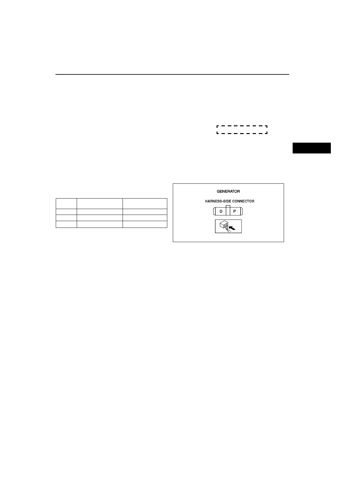
Generator
Voltage

1. Verify that the battery is fully charged.
2. Verify that the drive belt deflection/tension is correct. (See 

B–3 DRIVE BELT INSPECTION

.)

• If not as specified, replace the drive belt.

3. Turn off all electrical loads.
4. Turn the engine switch to start the engine and verify that the generator rotates smoothly without any noise while 

the engine is running.

5. Measure the voltage at the terminals shown in the table.

• If not as specified, repair or replace the 

generator as necessary.

Standard voltage

*

: Turn the following electrical loads on and verify that 

the voltage reading increases.
— Headlights
— Blower motor
— Rear window defroster

Current

1. Verify that the battery is fully charged.

• If the battery is not fully charged, charge the battery.

2. Verify that the drive belt deflection/tension is correct. (See 

B–3 DRIVE BELT INSPECTION

.)

• If not as specified, replace the drive belt.

3. Disconnect the negative battery cable.
4. Connect an ammeter, capable of reading 120 A or above, between generator terminal B and the wiring 

harness.

5. Connect the negative battery cable.
6. Turn off all electrical loards.
7. Start the engine and increase the engine speed to 2,000—2,500 rpm.
8. Turn the following electrical loads on and verify that the current reading increases.

• Headlights

• Blower motor

• Rear window defroster

— If generator terminal B current will not increase, repair or replace the generator as necessary.

Note

• Current required for generating power varies with electrical loads applied.

Terminal Ignition switch ON (V)

Idle (V) 

[20 

°C {68 °F}]

B

B+

13—15

P

Approx. 1

Approx. 3—8

D

Approx.  0

*

A6E4710W003

CHARGING SYSTEM , IGNITION SYSTEM 

G–8

Standard current (Reference)

Measuring conditions

Room temperature: 20 

°C {68 °F}

Voltage: 13.5 V
Engine hot

*

: Must not be 0 A

End Of Sie

IGNITION COIL REMOVAL/INSTALLATION

A6E471218110W01

1. Disconnect the negative battery cable.
2. Remove the plug hole plate.

End Of Sie

Engine 

speed 

(rpm)

Terminal B current (A)

L8

LF

L3

1,000

0*—80

2,000

0*—90

IGNITION SYSTEM

A6E4712W012

1

Connect

2

High-tension lead (See 

G–10–1 HIGH-TENSION 

LEAD REMOVAL/INSTALLATION

 )

3

Ignition coil

IGNITION SYSTEM 

G–9

G

IGNITION COIL INSPECTION

Primary Coil Winding

1. Remove the ignition coil.
2. Measure the resistance between the following lead holes using an ohmmeter.

• A and B, B and C

— If not specified, replace the ignition coil.

Specification

0.49—0.57 ohms [20

°C {68°F}]

Secondary Coil Winding

1. Remove the ignition coil.

• 1 and 4

• 2 and 3

— If not specified, replace the ignition coil.

Specification

 9.5—11.1kilohms 

A6E4712W003

A6E4712W001

G–10

IGNITION SYSTEM 

Insulation Resistance of Case

1. Disconnect the high-tension lead.
2. Disconnect the ignition coil connector.
3. Measure the insulation resistance between the following terminals and ignition coil case using an ohmmeter.

• Terminal B and ignition coil case.

— If not specified, replace the ignition coil.

Specification

Above 10 Megohm

End Of Sie

SPARK PLUG REMOVAL/INSTALLATION

A6E471218110W03

1. Disconnect the negative battery cable.
2. Remove the plug hoie plate.

• Lift off and remove the plug hole plate from 

the installation areas (rubber and clips) as 
shown in the figure.

3. Disconnect the high-tension lead.
4. Remove the spark plugs using the plug-wrench.
5. Install the spark plugs using a plug-wrench.

Tightening torque:

10—24 N·m {1.1—2.4kgf·m, 8—17ft·lbf}

End Of Sie

A6E4712W002

A6E4712W201

A6E4712W202


Content   ..  179  180  181  182   ..