Mazda 6. Manual - part 180


  Index      Mazda     Mazda 6 - service repair manual 2002 year


Search            


Content   ..  178  179  180  181   ..


Mazda 6. Manual - part 180


CHARGING SYSTEM 

G–3

G

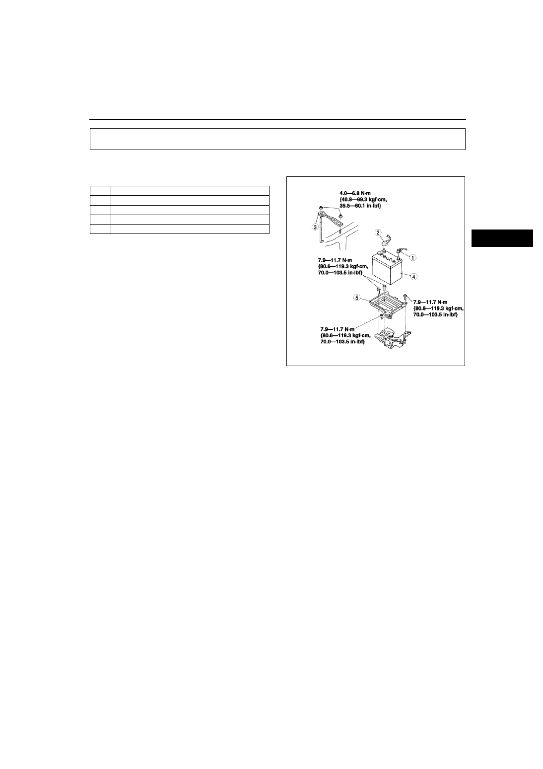
BATTERY REMOVAL/INSTALLATION

A6E471018520W01

1. Remove in the order indicated in the table.
2. Install in the reverse order of removal.

End Of Sie

CHARGING SYSTEM

1

Negative battery cable

2

Battery cable

3

Battery clamp

4

Battery

5

Battery tray

A6E4710W002

G–4

CHARGING SYSTEM 

BATTERY INSPECTION

A6E471018520W02

Battery

1. Inspect the battery in the following procedure.

Test load chart

Battery positive voltage with load

Back-up Current

1. Verify that the engine switch is at OFF and that the key has been removed.
2. Disconnect the negative battery cable.
3. Measure the back-up current between the negative battery terminal and the negative battery cable.

• If the current exceeds the maximum, remove the fuses in the main fuse block and the fuse block one by 

one while measuring the back-up current.
— Inspect and repair harnesses and connectors of the fuse at which the current decreases.

Back-up current

20 mA max.

Caution

• Operating electrical loads while measuring the back-up current can damage the circuit tester.

End Of Sie

Step

Inspection

Result

Action

1

Measure open circuit 
voltage of battery.

More than 
12.4 V

Go to 
Step 3.

Less than 
12.4 V

Go to 
next step.

2

Quick charge for 30 min. 
and recheck voltage.

More than 
12.4 V

Go to 
next step.

Less than 
12.4 V

Replace 
battery.

3

Apply load current (see load 
test chart) to battery using a 
battery load tester and 
record battery voltage after 
15 s. Is voltage more than 
specification?

Yes

Battery is 
okay.

No

Replace 
battery.

Battery

Load (A)

46B24DLS

135

50D20L

150

75D26L

195

80D26L

195

Approximate battery 

temperature

Min. voltage (V)

21 

°C {70 °F}

9.6

16 

°C {61 °F}

9.5

10 

°C {50 °F}

9.4

°C {39 °F}

9.3

–1 

°C {30 °F}

9.1

–7 

°C {19 °F}

8.9

–12 

°C {10 °F}

8.7

–18 

°C {0 °F}

8.5

CHARGING SYSTEM 

G–5

G

BATTERY RECHARGING

A6E471018520W03

Warning

• Keep any flammable away from the battery, otherwise evaporated gas of the battery fluid may 

catch fire, and cause serious injury or death.

Caution

• When removing the battery, disconnect the negative battery cable first and install it last to prevent 

damage to electrical components or the battery.

1. Place a battery in a pan of water to prevent it from overheating.
2. The water level should come up about halfway on the battery.
3. Remove the battery plugs while charging the battery.
4. Keep water off the top of the battery.

Caution

• To prevent damage to electrical components or the battery, turn all accessories off and stop the 

engine before performing maintenance or recharging the battery.

5. Connect a battery charger to the battery.
6. Adjust the charging current as follows.

End Of Sie

Battery type 

(5-hour rate)

Slow charge (A)

Quick charge

 (A / 30 min.)

46B24LS (36)

3.5—4.5

25

50D20L (40)

4.0—5.0

25

75D26L (52)

5.0—6.0

35

80D26L (55)

5.5—6.5

35

AME4710W001

G–6

CHARGING SYSTEM 

GENERATOR REMOVAL/INSTALLATION

A6E471018300W01

Warning

• When the battery cables are connected, touching the vehicle body with generator terminal B will 

generate sparks. This can cause personal injury, fire, and damage to the electrical components. 
Always disconnect the battery negative cables before performing the following operation.

Caution

• The generator can be damaged by the heat from the exhaust manifold. Make sure the generator 

duct and the generator heat insulator are installed securely.

1. Disconnect the negative battery cable.
2. Remove the under cover.
3. Disconnect the joint shaft from the drive shaft (RH). (R.H.D.) (See 

M–17 DRIVE SHAFT REMOVAL/

INSTALLATION

.)

4. Remove the drive belt. (See 

B–3 DRIVE BELT REPLACEMENT

.)

5. Remove in the order indicated in the table.
6. Install in the reverse order of removal.

Generator Removal Note

1. Remove the generator from above. (L.H.D.)
2. Remove the generator from below. (R.H.D.)

End Of Sie

AME4710W002

1

Generator duct

2

B terminal cable

3

Generator connector

4

Generator heat insulator

5

Generator
(See 

G–6 Generator Removal Note

)


Content   ..  178  179  180  181   ..