Mazda Protege 5. Manual - part 350
POWER SYSTEMS
09–21–1
09–21
09–21
POWER SYSTEMS
LOCATION INDEX . . . . . . . . . . . . . . . . . 09–21–1
FUSE SERVICE CAUTION . . . . . . . . . . . 09–21–2
MAIN FUSE REMOVAL/INSTALLATION 09–21–2
ROOM FUSE INSTALLATION . . . . . . . . 09–21–3
FUSE BLOCK
REMOVAL/INSTALLATION . . . . . . . . . 09–21–3
IGNITION SWITCH
REMOVAL/INSTALLATION . . . . . . . . . 09–21–3
IGNITION SWITCH INSPECTION . . . . . . 09–21–4
KEY REMINDER SWITCH
REMOVAL/INSTALLATION . . . . . . . . . . 09–21–4
KEY REMINDER SWITCH
INSPECTION . . . . . . . . . . . . . . . . . . . . . 09–21–4
RELAY INSPECTION . . . . . . . . . . . . . . . . 09–21–5
Relay type . . . . . . . . . . . . . . . . . . . . . . . 09–21–5
Four-terminal . . . . . . . . . . . . . . . . . . . . 09–21–5
Five-terminal . . . . . . . . . . . . . . . . . . . . . 09–21–6
Eight-terminal . . . . . . . . . . . . . . . . . . . . 09–21–7
End of Toc
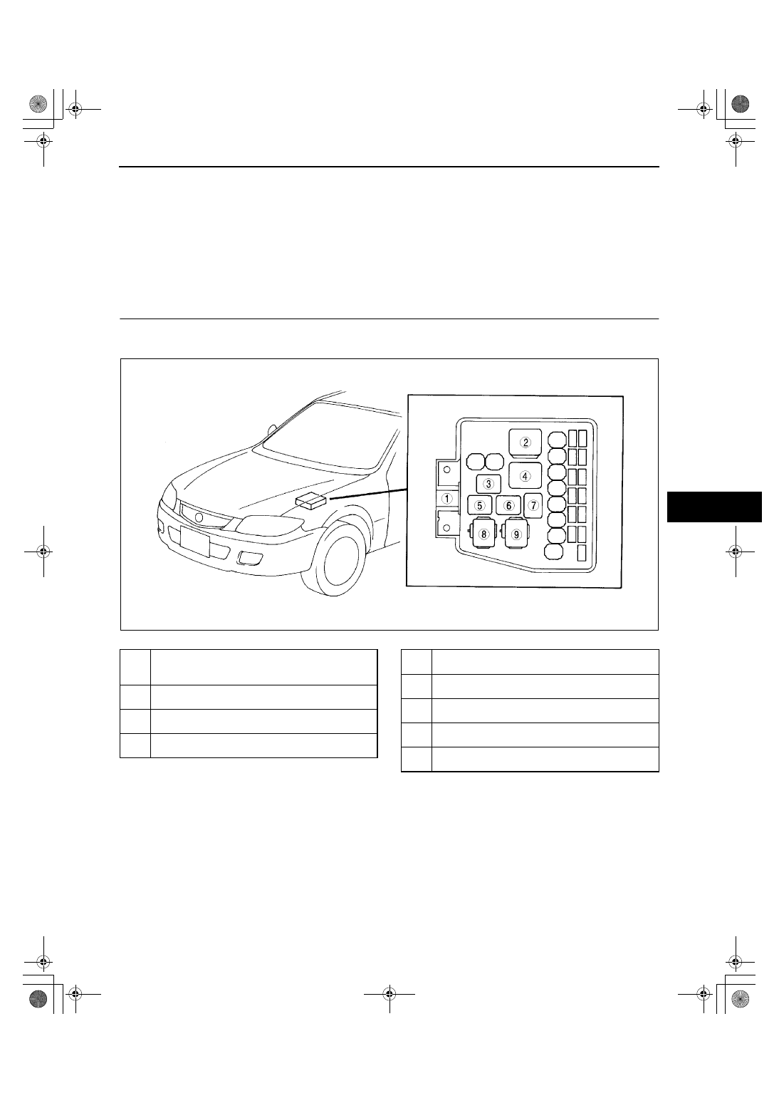
LOCATION INDEX
A3U092101072W01
.
Z3U0921W007
1
Main fuse
(See 09–21–2 MAIN FUSE REMOVAL/
INSTALLATION)
2
Fuel pump relay
(See 09–21–5 RELAY INSPECTION)
3
A/C relay
(See 09–21–5 RELAY INSPECTION)
4
Main relay
(See 09–21–5 RELAY INSPECTION)
5
TNS relay
(See 09–21–5 RELAY INSPECTION)
6
Horn relay
(See 09–21–5 RELAY INSPECTION)
7
Headlight relay
(See 09–21–5 RELAY INSPECTION)
8
Cooling fan relay
(See 09–21–5 RELAY INSPECTION)
9
Condenser fan relay
(See 09–21–5 RELAY INSPECTION)
1712-1U-01G(09-21).fm 1 ページ 2001年6月29日 金曜日 午前10時38分