Mazda Protege 5. Manual - part 349


  Index      Mazda     Mazda Protege 5 - service repair manual 2002 year


Search            


Content   ..  347  348  349  350   ..


Mazda Protege 5. Manual - part 349


ENTERTAINMENT 

09–20–6

REAR ANTENNA FEEDER INSPECTION

A3U092066942W02

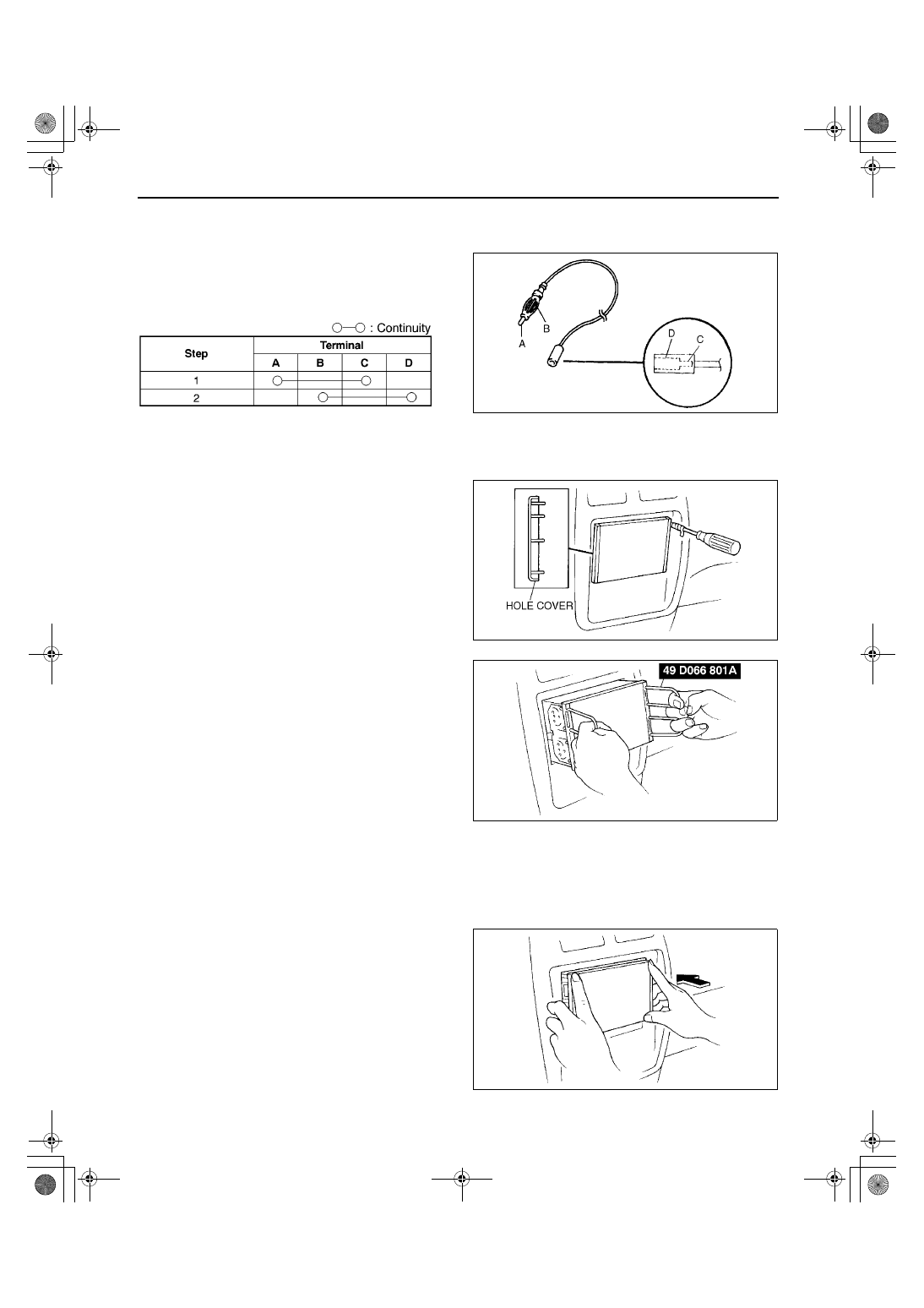
1. Remove the rear antenna feeder.
2. Verify that there is no continuity between rear antenna feeder terminals A and B using an ohmmeter.
3. Inspect for continuity between the rear antenna 

feeder terminals using an ohmmeter.

If not as specified, replace the rear antenna 
feeder.

End Of Sie

AUDIO UNIT REMOVAL

A3U092066900W01

1. Disconnect the negative battery cable.
2. Remove the hole covers by inserting a small 

tape-wrapped screwdriver into the slot and 
carefully pry them off without scratching the 
center panel. Pry up and pull off the hole covers 
carefully to prevent the posts from breaking off.

3. With the beveled parts of the SST facing inward, 

insert them into the unit.

Note

Two sets of the SSTs are necessary to 
remove the audio unit.

4. Pull the SST outward and forward to slide out the 

unit.

5. Disconnect the connectors and antenna jack.

End Of Sie

AUDIO UNIT INSTALLATION

A3U092066900W02

Caution

••••

Make certain that the wiring harness and antenna feeder are not caught between the unit and 
dashboard. If the harness or the antenna feeder is caught between the unit and dashboard, it may 
become the cause of trouble or malfunctions.

1. Connect the connectors and antenna jack.
2. Insert the unit until each clip clicks into place.

Caution

••••

To install audio unit, be sure to push 
service hole cover areas on both sides of 
the audio unit. If switches are pressed 
instead, it may become the cause of 
trouble or malfunctions.

3. Install the service hole covers.
4. Connect the negative battery cable.

End Of Sie

A3U0920W101

Y3A8124W002

YDE81241201

YDJ8124W107

YDJ8124W108

1712-1U-01G(09-20).fm  6 ページ  2001年6月29日 金曜日 午前10時37分

ENTERTAINMENT 

09–20–7

09–20

UPPER MODULE REMOVAL/INSTALLATION

A3U092066900W03

1. Disconnect the negative battery cable.
2. Remove the audio unit. (See 09–20–6 AUDIO UNIT REMOVAL.)
3. Remove in the order indicated in the table.

4. Install in the reverse order of removal.

Upper Module Removal Note

1. Insert a screwdriver into the hole stamped mark.
2. To remove upper module, lift it by pushing down 

the screwdriver’s handle.

Cover Removal Note

1. Insert a tape-wrapped screwdriver between the 

cover and the base unit, then unlatch hook A.

2. To unlatch hook B, pull the cover upward.

Screw Installation Note

Caution

••••

If an undesignated screw is used, the inside of the upper module could be damaged. When 
installing the module, be sure to use a designated screw (red).

1

Screw
(See 09–20–7 Screw Installation Note)

2

Upper module
(See 09–20–7 Upper Module Removal Note)

3

Cover
(See 09–20–7 Cover Removal Note)

Y5J8124W004

YLE8124W005

YLE8124W006

1712-1U-01G(09-20).fm  7 ページ  2001年6月29日 金曜日 午前10時37分

ENTERTAINMENT 

09–20–8

End Of Sie

LOWER MODULE REMOVAL/INSTALLATION

A3U092066900W04

1. Disconnect the negative battery cable.
2. Remove the audio unit. (See 09–20–6 AUDIO UNIT REMOVAL.)
3. Remove in the order indicated in the table.

4. Install in the reverse order of removal.

Cover Removal Note

1. Insert the SST into the service holes on the bottom surface of the lower module.
2. To remove the cover, push the SST in the 

direction shown by the arrow.

Screw Installation Note

Caution

••••

If an undesignated screw is used, the inside of the upper module could be damaged. When 
installing the module, be sure to use a designated screw (red).

End Of Sie

CIGARETTE LIGHTER REMOVAL/INSTALLATION

A3U092067000W01

1. Disconnect the negative battery cable.
2. Remove the console. (See 09–17–5 CONSOLE 

REMOVAL/INSTALLATION.)

3. Remove in the order indicated in the table.

4. Install in the reverse order of removal.

1

Cover
(See 09–20–8 Cover Removal Note)

2

Screw
(See 09–20–8 Screw Installation Note)

3

Lower module

YLE8124W007

ZLU0920W003

1

Cigarette lighter plug

2

Connector

3

Socket
(See 09–20–9 Socket Removal Note)

4

Ring
(See 09–20–9 Ring Removal Note)

X3U920WAG

1712-1U-01G(09-20).fm  8 ページ  2001年6月29日 金曜日 午前10時37分

ENTERTAINMENT 

09–20–9

09–20

Socket Removal Note

1. Turn the socket while pushing the protrusion of 

the ring through the hole of the socket with a 
tape-wrapped screwdriver.

2. Push the socket forward.

3. Return the socket clockwise to original angle 

position as shown to pull it out forward.

Ring Removal Note

1. Pull the ring forward while pushing the tabs.

End Of Sie

CIGARETTE LIGHTER INSPECTION

A3U092067000W02

1. Turn the ignition switch to ACC position.
2. Verify that the cigarette lighter plug will move normally within 10—20 seconds, after pressing the plug into the 

socket.

If the cigarette lighter does not operate normally, replace the cigarette lighter and socket. (See 09–20–8 
CIGARETTE LIGHTER REMOVAL/INSTALLATION.)

End Of Sie

X3U920WAH

X3U920WAJ

Y3U920WA3

1712-1U-01G(09-20).fm  9 ページ  2001年6月29日 金曜日 午前10時37分


Content   ..  347  348  349  350   ..