Range Rover. Manual - part 177


  Index      Land Rover     Range Rover P38 - service manual 1995 year


Search            


Content   ..  175  176  177  178   ..


Range Rover. Manual - part 177


STEERING

3

REPAIR

STEERING COLUMN INTERMEDIATE SHAFT

Service repair no - 57.40.22

WARNING: The intermediate shaft has a
red indicator clip fitted which must be
inspected at service, and after the vehicle

has been subjected to an impact. If the clip is not
present, or is not fully seated against the clamp
plate, a new assembly must be fitted
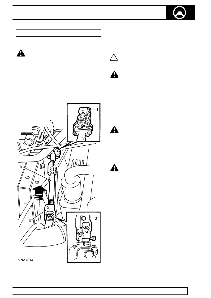
Remove

1. Remove bolt securing intermediate shaft

universal joint to steering column.

2. Remove 2 bolts securing universal joint to

intermediate shaft and steering box.

3. Set front road wheels to the straight ahead

position. Remove key from ignition switch.

NOTE: To centralise steering, align the rib
incorporated in the input shaft with two
marks on steering box casing.

WARNING: Do not turn the steering wheel
with intermediate shaft removed. The
rotary coupler may be damaged, leading to

possible malfunction of SRS and steering wheel
mounted switches.

4. Disengage universal joint from steering box by

pushing the universal joint up the splines.

5. Remove intermediate shaft from steering

column.

Refit

WARNING: Clean and inspect splines, if
damaged fit new components.

6. Ensure that steering box is still centralised. Fit

intermediate shaft to steering column and
steering box. Do not use a hammer or other
implement on the intermediate shaft to aid spline
engagement.

WARNING: Ensure that universal joints are
fully engaged. The bolt holes must align
with grooves on steering box and column,

and flat on intermediate column.

7. Fit bolts to universal joints. Tighten to

25 Nm

(18 lbf.ft)

8. Ensure indicator clip is correctly installed. It must

be fully seated against the clamp plate.

57

STEERING

NEW RANGE ROVER

4

REPAIR

DRAG LINK

Service repair no - 57.15.17

Remove

1. Raise the vehicle.

WARNING: Support on safety stands.

2. Remove nut and bolt securing steering damper

to drag link. Release damper.

3. RHD Remove right hand front road wheel.
4. LHD Remove left hand front road wheel.
5. Remove nut securing drag link to drop arm.
6. Remove nut securing drag link to swivel hub.
7. Break taper joints using LRT-57-018. Remove

drag link.

Disassemble

8. Slacken nut and bolt securing ball joint clamp.

Unscrew ball joint. Remove clamp.

9. Slacken nut and bolt securing adjuster clamp.

Unscrew adjuster. Remove clamp.

Assemble

10. Loosely fit adjuster clamp and adjuster.
11. Loosely fit ball joint clamp and ball joint.
12. Adjust drag link to nominal length of 1170 mm

±

10mm.

13. Orientate clamps as shown by illustration.
14. Secure clamps with nuts and bolts. Tighten to

8mm, 22 Nm (16 lbf.ft), 10mm, 47 Nm
(35 lbf.ft)

Refit

15. Use steering box centralising feature to

centralise box. Fit drag link.

16. Secure drag link to drop arm and swivel hubs

with nuts. Tighten to

50 Nm (37 lbf.ft)

17. Align damper to drag link. Secure with nut and

bolt, tighten to:-
Up to 97 MY -

125 Nm (92 lbf.ft)

97 MY on -

50 Nm (37 lbf.ft)

18. Remove safety stands. Lower vehicle.
19. Check front wheel alignment.

See Adjustment.

STEERING

5

REPAIR

STEERING DAMPER

Service repair no - 57.55.21

Remove

1. Raise the vehicle.

WARNING: Support on safety stands.

2. Remove damper fixings at both ends.

3. Remove damper.

Refit

4. Fit damper to chassis. Fit, but do not tighten nut

and bolt.

5. Fit damper to drag link, fit nut and bolt, tighten

to:-
Up to 97 MY -

125 Nm (92 lbf.ft)

97 MY on -

50 Nm (37 lbf.ft)

6. Tighten damper to chassis fixing. Tighten to

125Nm. (92 lbf.ft)

7. Remove safety stands. Lower vehicle.

PUMP FEED HOSE

Service repair no - 57.15.20

Remove

CAUTION: Seal all disconnected pipes and
ports to prevent ingress of dirt.

1. Disconnect battery earth lead.
2. Remove strap securing coolant top hose to

engine lifting bracket.

3. Release feed hose clips. Remove hose.

Refit

4. Reverse removal procedure.
5. Bleed power steering.

See this section.

57

STEERING

NEW RANGE ROVER

6

REPAIR

STEERING BOX FEED HOSE

Service repair no - 57.15.21

Remove

1. Disconnect battery earth lead.
2. Raise front of vehicle.

WARNING: Support on safety stands.

3. Remove nut securing PAS hose brackets to

steering box.

4. Release 2 hose brackets from steering box.
5. Position cloth to catch spillage.
6. Remove banjo bolt securing feed hose to

steering box. Remove and discard sealing
washers.

CAUTION: Plug the connections.

7. Position container to catch spillage.

8. V8 up to 99MY: Loosen union and disconnect

feed hose from PAS pump.

V8 from 99MY and diesel: Remove banjo bolt
securing feed hose to pump. Remove and
discard sealing washers.

CAUTION: Plug the connections.

9. Release PAS pipe from 2 radiator lower bracket

clips.

10. Remove pump feed hose.


Content   ..  175  176  177  178   ..