Range Rover. Manual - part 176


  Index      Land Rover     Range Rover P38 - service manual 1995 year


Search            


Content   ..  174  175  176  177   ..


Range Rover. Manual - part 176


STEERING

1

ADJUSTMENT

FRONT WHEEL ALIGNMENT

Service repair no - 57.65.01

1. Ensure tyre pressures are correct, vehicle is at

kerbside weight and on a level surface.

2. Release handbrake.
3. Roll vehicle backwards and forwards to relieve

stresses in steering/front suspension.

NOTE: Ensure that alignment equipment is
properly calibrated. Take an average of
three readings. Use recommended

equipment only.

4. Check that front wheel alignment is within

tolerance.

See GENERAL SPECIFICATION

DATA, Information.

Adjust

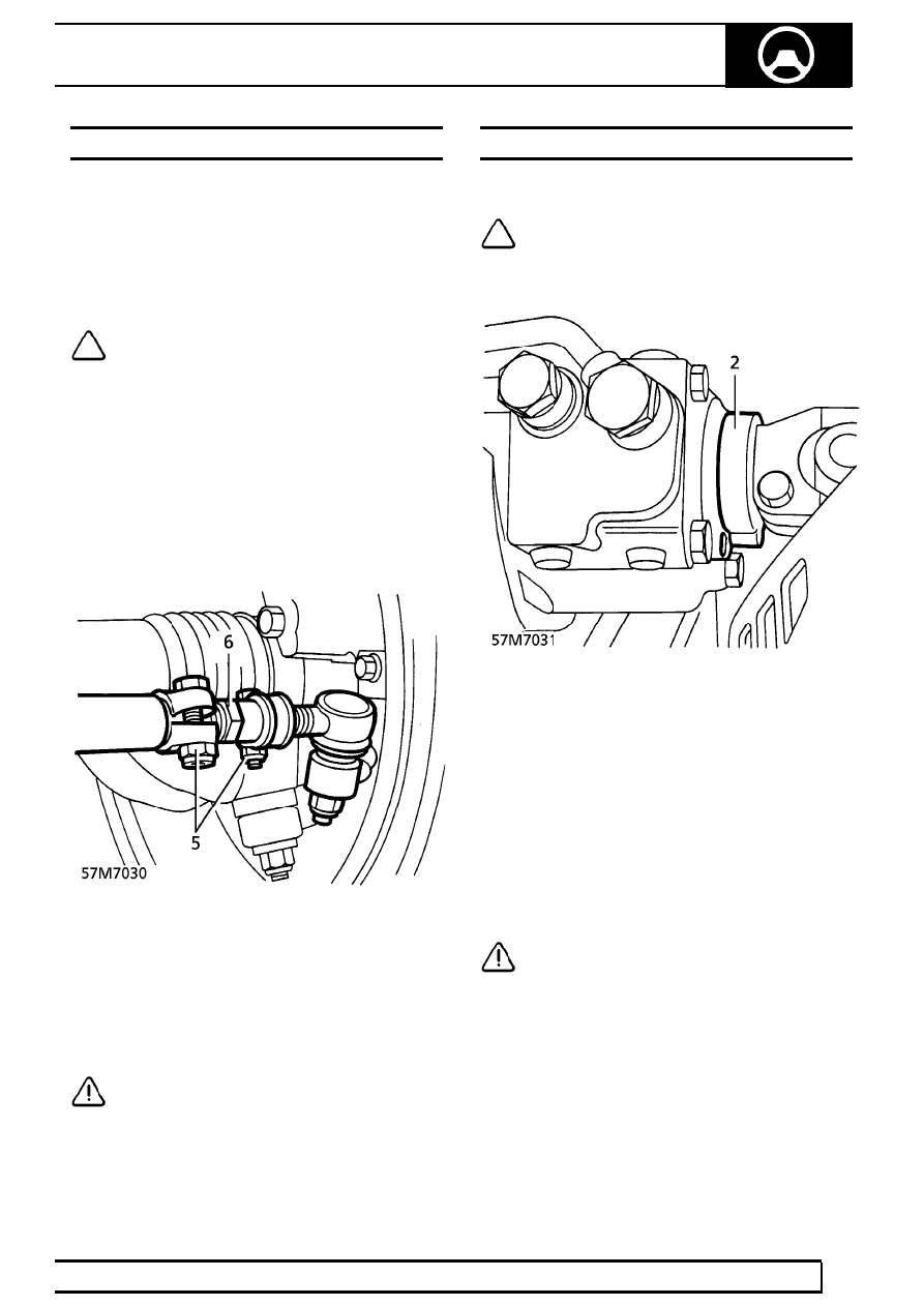
5. Slacken track rod adjuster clamping nuts and

bolts.

6. Rotate adjuster to give correct alignment.
7. Roll vehicle backwards and forwards to relieve

stresses in steering/front suspension.

8. Recheck front wheel alignment, taking average

of three readings.

9. Repeat procedure as necessary to obtain correct

alignment.

CAUTION: Ensure that adjuster clamping
nuts and bolts are positioned as shown or
wheel rim foul will result.

10. Tighten track rod adjuster fixings to

8mm, 22Nm

(16 lbf.ft), 10mm, 47Nm, (35 lbf.ft).

STEERING BOX CENTRALISATION

Check

NOTE: Markings on steering box and
pinion indicate when steering box is
centralised.

1. Move backward then forward by at least 2

vehicle lengths to ensure that road wheels are
pointing straight ahead.

2. Check for correct alignment of steering box

markings.

Adjust

3. Slacken drag link adjuster clamp nuts and bolts.
4. Rotate adjuster to align steering box.

CAUTION: Ensure adjuster clamp nuts and
bolts are positioned clear of drop arm.

57

STEERING

NEW RANGE ROVER

2

ADJUSTMENT

5. Recheck steering box alignment.
6. Tighten adjuster clamps to

8mm,

22 Nm (16 lbf.ft), 10mm, 47 Nm, (35 lbf.ft).

7. Check steering wheel for correct alignment. If

necessary, remove wheel and centralise.

See

Repair.

CAUTION: Repositioning of the steering
wheel on its splines cannot correct small
(less than 5

°

) errors in steering wheel

alignment. Always rectify small errors in
alignment by adjusting the drag link as detailed
above, ensuring that steering box centralisation is
maintained.

Road Test

8. Carry out a short road test over an even surface.

Check for correct alignment of steering wheel.
Ensure that vehicle follows a straight track.

LOCK STOP ADJUST

Service repair no - 57.65.03

Adjust

1. Raise the vehicle.

WARNING: Support on safety stands.

2. Slacken LH lock stop locknut. Screw stop bolt

clockwise, fully into hub.

3. With assistance, start the engine, turn steering

onto right hand lock until resistance is felt.

NOTE: Resistance is created by hydraulic
limiter inside steering box.

4. With the steering held, unscrew anti-clockwise,

stop bolt until it contacts the axle. Screw bolt
back in clockwise, by 3 flats.

5. Tighten locknut.
6. Return steering to centre. Turn back to full right

hand lock to check adjustment.

NOTE: Resistance should be felt prior to
lock stop operation.

7. Repeat for RH lock stop.
8. Stop engine.
9. Remove safety stands. Lower vehicle.

STEERING

1

REPAIR

STEERING COLUMN

Service repair no - 57.40.01

WARNING: Under no circumstances must
any form of lubricant be applied to the
steering column. If noise or harshness is

present in the column a new unit must be fitted

Remove

1. Disconnect battery negative lead.

WARNING: If vehicle is fitted with SRS,
disconnect both battery terminals. Always
disconnect negative terminal first.

2. Remove intermediate steering shaft.

See this

section.

3. Remove 4 scrivet fasteners securing closing

panel beneath steering column.

4. Release closing panel from fascia. Disconnect

footwell lamp multiplug, remove panel.

5. Remove steering column nacelle.

See this

section.

6. Remove screws securing indicator switch stalk

to column. Release stalk, remove from multiplug.

7. Remove screws securing wiper switch stalk to

column. Release stalk, remove from multiplug.

8. Disconnect ignition switch, ’key in’ sensor, rotary

coupler and SRS system multiplugs.

57

STEERING

NEW RANGE ROVER

2

REPAIR

WARNING: The SRS connector beneath
the steering column must be disconnected
prior to removal of the air bag module.

9. Remove 2 clips securing SRS harness to

steering column harness.

10. Release clip securing harness to column.
11. Release illumination bulb from lock barrel.

Release bulb harness from clip.

12. Disconnect multiplug from key inhibit solenoid

(shift interlock).

13. Release duct from drivers blower motor housing,

remove duct from heater unit.

14. Remove 2 bolts securing column to bulkhead.

15. Remove 2 bolts and 2 nuts securing column to

pedal box.

16. Remove steering column assembly.

Refit

17. Position steering column assembly and engage

to pedal box studs.

NOTE: Tighten the steering column fixings
in the following sequence.

18. Fit bolts securing steering column to bulkhead.

Tighten to

25 Nm (18 lbf.ft)

19. Fit nuts securing steering column to pedal box.

Tighten to

25 Nm (18 lbf.ft)

20. Fit bolts securing steering column to pedal box.

Tighten to

25 Nm (18 lbf.ft)

21. Fit blower motor duct.
22. Connect column multiplugs. Secure ignition lock

illumination bulb in holder, position bulb harness
in clip.

23. Secure column harness clip to column bracket.
24. Connect SRS multiplug and secure SRS

harness to column harness with clips.

25. Connect wiper switch stalk to multiplug, and

secure stalk to column with Torx fixings.

26. Fit steering column nacelle.

See this section.

27. Position closing panel. Connect footwell lamp.

Align and secure closing panel with scrivet
fasteners.

28. Fit intermediate steering shaft.

See this

section.

29. Connect battery terminals, positive before

negative. Fit battery cover.


Content   ..  174  175  176  177   ..