Range Rover. Manual - part 137


  Index      Land Rover     Range Rover P38 - service manual 1995 year


Search            


Content   ..  135  136  137  138   ..


Range Rover. Manual - part 137


CLUTCH

3

REPAIR

Refit

16. Ensure mating faces are clean.

NOTE: New friction plates are supplied
with splines pre-greased.

17. If refitting existing friction plate, smear splines

with ’Molycote FB180’.

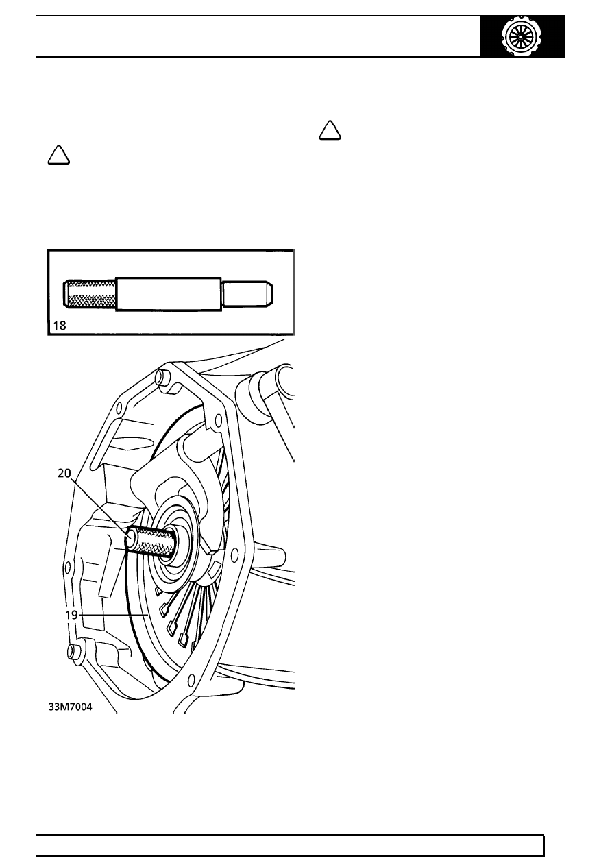
18. Position friction plate on flywheel. Fit

LRT-12-001 to align plate.

19. Position cover. Locate on dowels.

NOTE: If original cover is refitted, align
marks.

20. Secure cover with bolts. Tighten progressively,

in a diagonal sequence to

40 Nm (30 lbf.ft).

Remove LRT-12-001.

21. Position clutch housing onto dowels. Ensure

release fork engages with release bearing.

22. Secure clutch housing with bolts. Tighten to

40 Nm (30 lbf.ft)

23. Position flywheel access cover. Secure with

bolts.

24. Smear release lever push rod socket with

’Molycote FB180’.

25. Position slave cylinder on clutch housing.

Ensure pushrod is engaged with lever. Secure
cylinder with bolts. Tighten to

45 Nm (33 lbf.ft)

26. Secure push rod gaiter to clutch lever.
27. Fit gearbox assembly.

See MANUAL

GEARBOX, Repair.

33

CLUTCH

NEW RANGE ROVER

4

REPAIR

CLUTCH ASSEMBLY - DIESEL

Service repair no - 33.10.07

Remove

1. Remove gearbox assembly.

See MANUAL

GEARBOX, Repair.

2. Remove starter motor.

See ELECTRICAL,

Repair.

3. Release push rod gaiter from clutch lever.

4. Remove 2 bolts securing clutch slave cylinder.

Tie cylinder aside.

5. Release clutch fluid pipe from clips. Move pipe

bracket clear of clutch housing.

6. Remove 7 remaining bolts securing clutch

housing. Disengage release lever from release
bearing. Remove clutch housing.

NOTE: Spacer plate may become detached
from dowels but remain captive behind
flywheel.

7. If clutch cover is to be refitted, mark cover and

flywheel to aid re-assembly.

8. Fit LRT-12-106 to flywheel. Secure tool to

cylinder block with bolts.

CLUTCH

5

REPAIR

9. Working diagonally, sequentially slacken 6 bolts

securing clutch cover to flywheel. Remove bolts.

10. Remove cover assembly. Collect friction plate.

Check

11. Check linings of friction plate for excessive or

uneven wear, burning or contamination.

12. Check splines of friction plate for excessive

wear.

13. Check friction surface of cover for burning,

distortion or scoring.

14. Check fingers of cover for cracks and distortion.
15. Check release bearing for smooth operation.
16. Renew components as necessary.

CAUTION: Release bearing is packed with
grease, do not wash in solvent.

Refit

17. Ensure mating faces are clean.

NOTE: New friction plates are supplied
with splines pre-greased.

18. Smear friction plate splines with ’Molycote BR2’.
19. Position friction plate on flywheel. Fit

LRT-12-123 to align plate.

20. Position cover, locate on dowels.

NOTE: If original cover is refitted, align
marks.

21. Secure cover with bolts. Tighten progressively,

in a diagonal sequence, to:
M8 8.8 -

24 Nm (18 lbf.ft)

M8 10.9 -

34 Nm (25 lbf.ft)

22. Remove LRT-12-123 and LRT-12-106.
23. Position spacer plate onto dowels.
24. Position clutch housing onto dowels. Ensure

release fork engages with release bearing.

25. Align clutch fluid pipe bracket and coolant pipe

with clutch housing.

26. Secure clutch housing with bolts.

M8 - Tighten to

27 Nm (20 lbf .ft)

M10 - Tighten to

51 Nm (38 lbf.ft)

M12 - Tighten to

86 Nm (63 lbf.ft)

27. Smear push rod socket of release lever with

’Molycote FB180’.

28. Position slave cylinder on clutch housing.

Ensure push rod has engaged with lever. Secure
cylinder with bolts. Tighten to

45 Nm (33 lbf.ft)

29. Secure push rod gaiter to clutch lever.
30. Secure fluid pipe to clips.
31. Fit starter motor.

See ELECTRICAL, Repair.

32. Fit gearbox assembly.

See MANUAL

GEARBOX, Repair.

33

CLUTCH

NEW RANGE ROVER

6

REPAIR

MASTER CYLINDER

Service repair no - 33.20.01

Remove

1. Remove fascia closing panel.

See CHASSIS

AND BODY, Repair.

2. Remove 4 scrivets securing lower closing panel.

Disconnect multiplug from footwell lamp.
Remove panel.

3. Remove spring clip and clevis pin from master

cylinder push rod.

4. Position cloth beneath master cylinder to absorb

fluid spillage.

CAUTION: Do not allow brake fluid to
contact painted surfaces. Paint damage
will occur. If spilled, remove fluid. Wash

area with clean warm water.

5. Disconnect reservoir hose from master cylinder.

Plug hose and connection.

6. Disconnect pressure pipe from master cylinder.

Plug pipe and connection.

7. Remove 2 nuts securing master cylinder to

bulkhead. Remove master cylinder.

Refit

8. Ensure mating faces are clean.
9. Reverse removal procedure.

10. Bleed clutch system.

See this section.


Content   ..  135  136  137  138   ..