Discovery 2. Manual - part 326
ALARM SYSTEM AND HORN
DESCRIPTION AND OPERATION
86-4-9
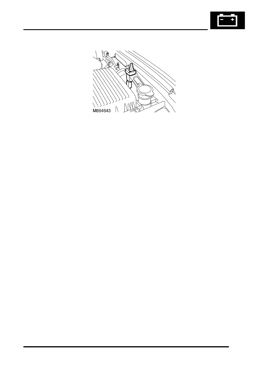
Bonnet switch
The BCU uses a plunger type switch to determine if the bonnet has been forcibly opened when the alarm has been
set. The switch is located under the bonnet on the left hand side of the vehicle when viewed from the rear.
Input/Output
When the bonnet is closed the bonnet activated alarm switch is in an open condition and the input to the BCU is more
than 6 volts, in which case the BCU pulls the input high internally. When the bonnet is open the bonnet activated alarm
switch is closed and the input to the BCU is less than 2 volts.
The bonnet activated alarm switch has a dedicated signal input to the BCU. This allows the BCU to identify the
position of the bonnet.
TestBook provides the ability to monitor the real time state of the switch.