Land Rover Discovery. Manual - part 131


  Index      Land Rover     Land Rover Discovery - service 1995-1996 year


Search            


Content   ..  129  130  131  132   ..


Land Rover Discovery. Manual - part 131


57

STEERING

4

DESCRIPTION AND OPERATION

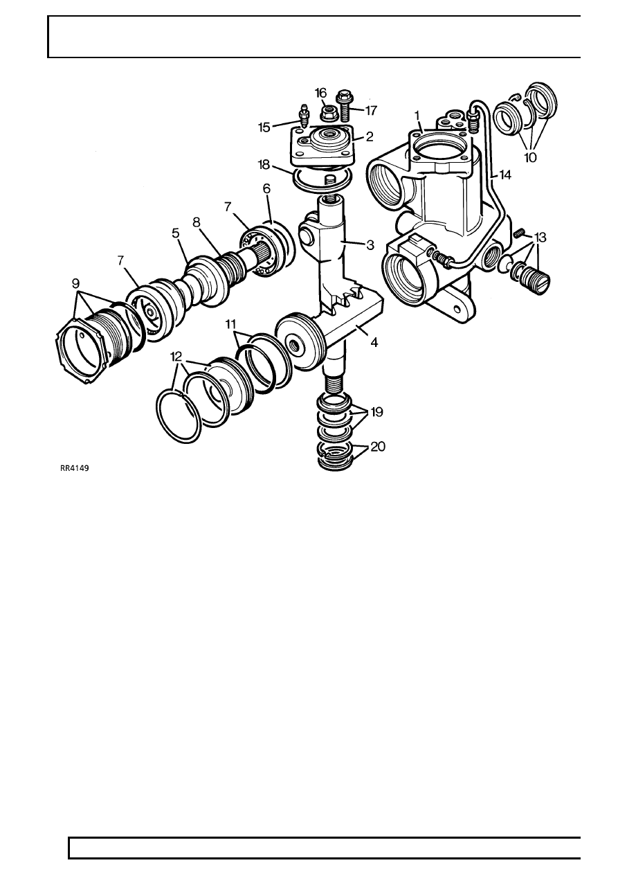
Power steering box components

1. Housing complete with sector shaft bearings
2. Cover plate complete with bearing
3. Sector shaft
4. Hydraulic piston/rack
5. Worm/valve and torsion bar assembly
6. Shims for centralizing worm/valve
7. Ball race (2)
8. ’Teflon’ seals for valve sleeve (3)
9. Bearing adjuster, locknut and seal

10. Worm shaft pressure seal, circlip and dirt

excluder

11. ’Teflon’ and rubber seal for piston
12. End cover seal and snap ring
13. Adjustment components for piston/rack
14. Hydraulic pipe
15. Bleed screw
16. Sector shaft adjustment lock nut with seal
17. Cover plate bolts (4)
18. Cover plate seal
19. Seal, washer and backup seal
20. Circlip and dust cover

STEERING

5

DESCRIPTION AND OPERATION

Rotary valve operation

The rotary valve assembly seen in RR3620M
comprises the worm (1), the valve sleeve (2), the input
shaft (4) and the torsion bar (5).

The valve sleeve is retained inside the worm by the
trim screw (3), and incorporates valve ports in its inner
bore. The input shaft is attached to the steering wheel
via the steering shaft and steering column and
incorporates valve ports in its outer diameter to align
with those in the sleeve. The torsion bar which is
secured to the worm and input shaft with pins (6) at
each end (later models use one pin at input shaft
end), holds the valve ports in neutral alignment when
there is no demand for assistance.

No demand for assistance (Valve at neutral)

When there is no demand for assistance as seen in
RR3620M, the torsion bar holds the input shaft and
sleeve valve ports in neutral relationship to one
another, allowing equal pump pressure A to both
sides of the piston/rack (9). Any excess fluid flow from
the pump returns to the reservoir via B.

Rotary valve at neutral

57

STEERING

6

DESCRIPTION AND OPERATION

Demand for assistance (Valve misaligned)

When the steering wheel and input shaft is turned,
steering resistance transmitted to the worm causes
the torsion bar to be twisted and the valve ports to be
misaligned for a right or left turn. The misalignment of
the valve ports directs all fluid pressure A to one side
of the piston only and allows displaced fluid B on the
other side.

When demanding maximum assistance, any
excessive fluid output from the pump due to high
pump speed, will circulate through the regulator valve
located in the pump unit, causing the temperature of
the fluid and the pump to rise rapidly.
To avoid excessive fluid temperatures which could
damage the oil seals, the steering must not be held on
full lock for more that 30 seconds in one minute.

Only when the steering wheel and the demand for
assistance is released, will the torsion bar return the
valve to neutral, allowing the fluid to circulate through
the reservoir where it is cooled.

In the unlikely event of mechanical failure of the
torsion bar, a coarse splined connection (7) between
the input shaft and worm, ensures steering control is
maintained sufficient to allow the vehicle to be
recovered.

Rotary valve misaligned

STEERING

7

DESCRIPTION AND OPERATION

Pump and regulator valve operation

The pump which is belt driven from the engine is an
eccentric roller type and also houses the pressure
regulator and flow control valve. The pressure is
controlled by a spring loaded ball valve 3 which is
housed inside the flow control valve piston 4.

No demand for assistance High flow through box -
Low pressure

With no demand for assistance as illustrated in
RR3568M the rotary valve in the steering box acts as
a pressure relief valve, allowing fluid A to flow freely
through the steering box and back to the reservoir and
pump inlet B.

No demand for assistance

1. Reservoir
2. Pump
3. Pressure control ball valve and spring
4. Flow control valve and spring
5. Press fit plug (ball bearing)
6. Restrictor

The ball plug item 5 is pressed into the valve 4
during manufacture and determines the opening
pressure of pressure relief valve 3.

No flow, through box - High pressure

When the steering is turned, the rotary valve
effectively stops all fluid flow through the steering box,
thus causing an increase in pressure A. This increase
in pressure is felt in the flow control valve spring
chamber where, at a pre-determined pressure the
relief valve 3 will open and allow the pressure to
escape. The fall in pressure in the flow control spring
chamber, allows the flow control valve to move to the
right, which in turn allows pump output A to escape
directly into the pump inlet B, as seen in RR3569M.

Assistance demanded

As soon as the steering wheel is released after
making a turn, the system reverts to the condition
seen in RR3568M and the road wheels are returned
to the straight ahead position by the mechanical
steering geometry.

In the event of any hydraulic failure steering control
though heavy, will be maintained through the
mechanical components in the steering box.


Content   ..  129  130  131  132   ..