Land Rover Discovery. Manual - part 130
FRONT AXLE AND FINAL DRIVE
3
SERVICE TOOLS
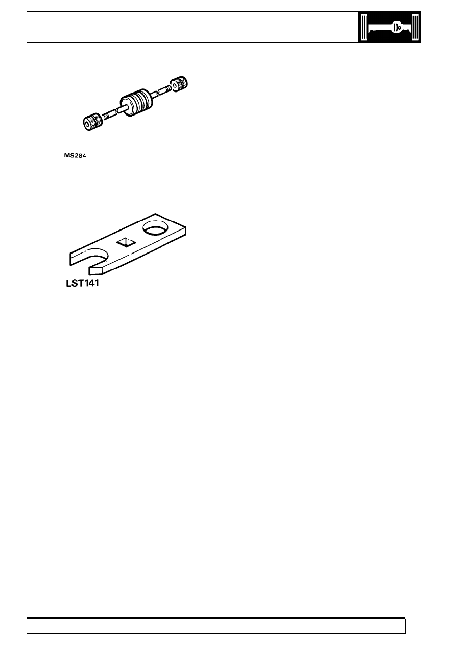
LRT-99-004
Impulse extractor
MS284
LRT-570-024
Torque test adaptor ABS
LST141
|
|
|
FRONT AXLE AND FINAL DRIVE 3 SERVICE TOOLS LRT-99-004 Impulse extractor MS284 LRT-570-024 Torque test adaptor ABS LST141 |