Defender 90 / 110 / 130. Manual - part 76


  Index      Land Rover     Defender 90 / 110 / 130 - service repair manual


Search            


Content   ..  74  75  76  77   ..


Defender 90 / 110 / 130. Manual - part 76


TRANSFER GEARBOX 

218.  Repeat  above  procedure  and  fit  the  rear  taper 

roller bearing. 

219.  Lubricate both bearings with oil. 
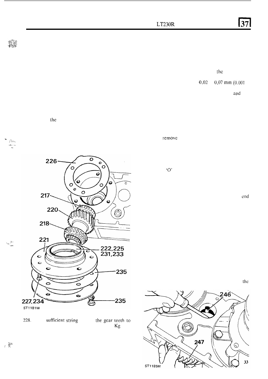
220.  Fit  input gear assembly into the transfer  box from 

t h e  

rear (gear end 

first). 

Obtaining  bearing  pre-load 

with  intermediate  gear 

cluster removed 

221.  Secure the mainshaft bearing housing in the vice. 
222.  Press  out  the  rear  input  gear  bearing  cup  and 

223.  Clean  the  main  bearing  housing  and  measure 

224.  Fit  the original shim to the main bearing housing. 
225.  Locate 

rear 

bearing  cup on  the  main  bearing 

226.  Apply  grease  to  the  gasket  and  fit  onto  the 

2-27.  Fit  the main  bearing  housing  and  tighten  the  two 

remove the shim behind it. 

original shim, noting its thickness. 

housing and press 

it 

fully 

home. 

ransfcr box casing 

securing screws 

to the specified torque. 

... 

... 

. I .  

... 

Wind 

around 

rotate the input gear. pull  of  1,4 to 3,6 

( 3  to 

8 Ib)  is  required  on  the  spring  balance.  This 
applies to new 

or used bearings. 

229.  If  the  reading  obtained  is  outside  the  above 

limits  the  original  shim  must  be  changed 
accordingly. 

230.  Remove  t h e   two  screws  retaining  the  mainshaft 

bearing housing. 

231.  Press  out  the  rear  bearing  cup  from  the  bearing 

housing and remove and discard 

original shim. 

232.  Select  a shim  to  the  required  thickness  to  obtain 

t h e  

correct  pre-load 

of 

to 

to 

0.003 in) on reassembly. 

233. 

Fit  the shim  to the main bearing housing 

then 

press the rear bearing cup into position. 

234. 

Fit  the  main  bearing  housing  and  tighten  the  two 

securing screws 

to the specified torque. 

235.  Grease and  fit  P.T.O. cover gasket  and  finally 

fit 

the  P.T.O.  cover  securing 

it 

with  six  bolts  (with 

plain washers) to the specified torque. 

Intermediate gear assembly 

Keassembly 

236.  First 

the needle  roller bearings and spacer 

from the gcar assembly. 

237.  Clean  the parts,  including  the thrust  washers  and 

lock  plate  and  examine  for  wear  or  damage, 
renew  as  necessary.  Refer  to  D A T A   at  end 

of 

section 

for thrust washer thickness. 

238.  Fit the 

ring to 

t h e  

intermediate shaft. 

239.  Fit the 

'0' 

ring into the front of 

t h e  

transfer case. 

240.  Lubricate  thrust  washers,  bearings,  shaft  and 

241.  Fit needle bearings with spacer interposed. 

spacer. 

If  the bearings have plastic cages, the flangcd 
of  each  cage  must  face  the thrust  washers,  when 
fitted. 

242.  Fit  front  thrust  washer  to  slot  in  transfer  (plain 

side to case). 

243.  Locate  gear  assembly  partially  into  the  transfer 

case 

so that 

it 

rests on the front thrust washer. 

244.  Locate  rear  thrust  washer (plain  side uppermost) 

into slot in transfer case. 

245.  Gently push gear assembly into mesh. 
246.  Using  a  screwdriver  through  the  intermediate 

shaft hole guide the locating tab on the rear thrust 
washer into the slot provided 

in 

the transfer case. 

247.  Align  gear  and  thrust  assembly  and  slide  the 

intermediate shaft  into  the  transfer  box  from  the 
rear. 

248.  Align  the  shaft  so  that  the  lock  plate  slot 

in 

end is on 

top. 

NOTE:  The  pre-load  can  only  be  measured  while 

the  Transfer  gearbox  is  separated  from 

the 

main 

gear 

box. 

TRANSFER GEARBOX 

249.  Apply  Loctite  290  to  the  lock  plate  bolt  threads. 

Locate  lock  plate 

into  position  and  fit  securing 

bolt (with spring washer). 

250.- Using a screwdriver via the bottom  of  the transfer 

case  lift  up  the  gear  assembly  and  measure  the 
end-float  with  feeler  gauges.  This  should  be 
between 

and 

(0.003 and 0.014  in). 

251.  Grease and 

fit 

the bottom 

gasket. 

252.  Apply  Loctite  290  to  the  ten  bottom  cover fixing 

253. 

Clean and fit the bottom cover, using 

the 

bolts 

bolts only. 

(with spring washers). 

Transmission brake assembly 

254.  Clean  brake  backplate  and  oil  drip  plate  and 

apply  silicone  rubber  sealant.  Locate  the 

on 

rear  output 

housing 

so 

that 

brake operating lever 

is on the 

right-side rear. 

255.  Fit  the  four  Brako  Durlok  bolts,  the  lower  two 

with  plain  washers,  also  retain  t h e  oil  drip plate. 

Tighten 

to 

specified torque. 

256.  Clean  and 

fit 

brake  drum  and 

fit 

the  two 

countersunk retaining screws. 

34 

257,261 

259 

gear change housing 

Overhaul 

(Instructions 262 to 298) 

Dismantling 

262.  Remove the split pin  from the clevis pin at the top 

of  the  differential  lock  cross  shaft  lever  which 
secures it 

to the gear change cross shaft. 

263.  Remove  the  washer  and  clevis  pin  and  the 

rattle nylon strip. 

264.  Mark  the  position  of  the 

gcar  change 

operating  arm  on  the  splined  shaft  o f   the  gcar 
change crank arm. 

265.  Slacken the clamp bolt  and remove the operating 

arm. 

266.  Remove  the  four  bolts  from  the  top  of  the  gear 

change  housing  and 

iift 

off 

the  grommet 

grommet, gate plate and gasket. 

267.  Remove the split  pin  from 

t h e  

gear change crank 

arm clevis pin and remove the clevis pin. 

268.  Remove the circlip from 

t h e  

gear change 

lever bush. 

269.  Withdraw the gear change lever from the housing, 

with ball and 

bush. 

Differential lock switch adjustment 

257.  Select  differential  locked  position  by  moving  the 

differential lock lever towards the right side of the 
transfer box. 

258.  Obtain a battery and connect a test lamp circuit to 

the differential lock switch. 

Slacken  the  lock  nut  off  and  screw 

in  the  lock 

switch until the bulb is illuminated. 

260.  Turn the lock switch another half  turn  and tighten 

the lock nut against t h e  housing. 

261.  Disconnect  t h e  battery  and  move  the  differential 

lock  lever towards the left  side of  the transfer  box 
to disengage 

differential lock. 

TRANSFER GEARBOX 

... 

.. 

... 

270.  Rcmove  the  two  countersunk  screws  from  t h e  

271.  Remove the housing end cover. 

Remove the two 

rings from the end cover. 

273.  Remove 

cross shaft from the housing. 

274.  Compress  t h e  detent spring and  remove 

t h e  

gcar 

change 

from 

inside the housing. 

housing end cover. 

Reassem biy 

279. 

Fit the two 

rings to the housing end cover. 

280.  Fit the two 

rings to the gear change crank arm. 

281.  Lubricate 

rings with oil. 

282.  Clip the detent spring onto the detent plate. 
283.  Fit  detent  plate assembly  into housing  and  retain 

from  outside  with  two  Nyloc  nuts 

(with 

plain 

washers). 

284.  Compress 

detent  spring  and  f i t   the  gear 

change crank arm 

in 

t h e  

housing. 

285. 

Fit  cross  shaft  into  position  locating  end  in  the 

crank arm. 

286.  Fit the housing end cover to support the other end 

of the cross shaft. 

287.  Finally secure the housing end cover with the two 

countersunk screws. 

288.  Before refitting the gear change lever remove the 

clevis  pin  bushes  and  the  Nylon  socket  bush  and 

ball. 

289.  Clean  all  parts,  examine  for 

o r   damage, 

renew as necessary. 
Fit  and  grease  gear  lever  ball  and  Nylon  socket 
bush to gear lever. 

291.  Fit and grease clcvis pin bushes. 
292.  Locatc  gear change  lever assembly  in  cross  shaft 

(do  not 

fit 

socket  bush  retaining  circlip  at  this 

stage). 

293.  Align  gear change  lever  end with  crank  arm  fork 

ensuring 

the gear  lever is 

and 

fit 

clcvis and split pin. 

294.  Finally secure Nylon  socket bush with circlip. 
295.  Grease and 

fit 

gasket to 

change housing face. 

296. 

Fit the 

plate. 

297.  Fit the grommet. 
298.  Fit  the  grommet  plate  and  retain  with  the  four 

securing bolts (with spring washers). 

275.  Remove t h e  two 

‘0’ 

rings from the crank arm. 

276.  Remove and discard the two  Nyloc nuts retaining 

277.  Remove  the  detent  plate  and  spring  from  the 

278.  Clean  all  parts, 

for  wear  or  damage, 

the detent plate. 

housing. 

renew as necessary. 

35 

TRANSFER GEARBOX 

299.  Before  refitting  the 

connecting  rod  and 

gear change operating arms remove the respective 
clevis  pins  and  Nylon  bushes.  Clean  and examine 
for wear 

or damage, renew as necessary. 

300.  Grease  and  fit  the  Nylon  bushes  to 

selector and gear change opcrating arms. 

301.  Assemble  both  operating arms to  the  connecting 

rod with clcvis pin, plain washer and split pin. 

302.  Slacken the gear change operating arm clamp bolt 

and  fit  the  operating  arm 

on  to  the  splined  shaft 

projecting  from  the 

gear  change 

housing, carefully aligning 

it 

to the marks 

on both 

303.  Tighten the clamp bolt to the specified torque. 

304.  Before  refitting  the  differential  lock  cross  shaft 

lever  and  pivot  bracket  remove  the  respective 

clevis  pins  and  Nylon  bushes.  Also  remove  the 
split  pin  retaining  the  cranked  lever  and 
disconnect  it.  Clean  and  examine  for  wear 

or 

damage, renew as necessary. 

305.- 

Fit 

the  cranked  lever  to  the  bottom  of 

cross 

shaft  lever  and  secure  with  a  new  split  pin  (with 
plain washer). 

NOTE:  Early  gearboxes  were  fitted  with 

short 

connecting link secured by a ‘Nyloc’ nut. 

306.  Grease  and 

fit 

t h e  

Nylon 

bushes  to  the  middle 

pivot of  the cross shaft lever. 

307.  Fit  the  cross  shaft  lever  to 

(loose)  pivot 

bracket with the clevis pin, washer and split pin. 

308.  Fit  the  cross  shaft  lever  fork  (top)  to 

gear 

change cross shaft. 

309.  Locate the anti-rattle Nylon strip and 

fit 

t h e  

clevis 

pin, plain  washer and split pin. 

310.  Fit  the  cranked  lever, 

at 

bottom  of  the 

differential  lock cross shaft lever, to the lock lever 
and  retain  the  clevis  pin  and  plain  washer  with  a 
new split pin. 

311.  Grease and 

fit 

the Nylon  bushes  to  the  operating 

arm on the selector housing cross shaft. 

Adjustment of 

connecting rod 

312. 

313. 

314. 

316. 

317. 
318. 

319. 
36 

This  operation  is  carried  out  in  situ  or  on  the 
bench, after assembly to the main gearbox. 
Remove  the 

four  bolts  from  the  top  of  the  gear 

changc housing  and  lift  off 

gear  changc lever 

grommet  plate  and  the  gcar  change  lever 
grommet.  Replace  the  four  bolts 

to 

retain the gate plate in position. 
Check  that 

t h e  

gear  lever  does  not  foul 

t h e  

gate 

plate  when  high  or  low  range  is  selected. 

If 

adjustment  is  required  carry  out  the  following 
procedure. 

*Slacken off the connecting rod locknuts. 

Move  gear  change  lever  into  high  range 
(rearwards)  and  move  the  operating  arm  on  the 

selector  housing  cross  shaft  into  high  range 
(forwards). 
Tighten 
Check that the gear change lever does not  foul the 
gate plate 

in this position. 

Engage and check  low range in the same way. 

320.  After  adjustment  return  the gear change  lever to 

the high range position. 

321.  Remove the four bolts retaining the gate plate and 

refit the grommet and grommet plate. 

322.  Refit the four bolts (with spring washers). 

On  early versions  of  the  transfer gearbox a different 
connecting  rod  fork  end  was  used  with  a  single 
locknut. 

In 

this  case  the  following  method  of 

adjustment is recommended. 

(a)  Disconnect  t h e   top  of  the  differential  lock 

cross  shaft  lever  from  the  gear  change  cross 
shaft. 

(b)  Remove  the  four  bolts  retaining  the  gear 

change  housing  to  the 

gear  change 

housing on 

the 

main gearbox. 

(c)  Lift  up  the  housing  assembly  (with  the 

connecting  rod  attached)  and  rotate 

it 

as 

required 

to  vary  the  length  of 

the 

connecting 

rod. 

Transfer box mounting 

Refitting 

323.  Fit 

rubber  mounting plate  to the  right  sidc of 

the  front  output  housing  by  fitting  the  four 
securing bolts (with new lock tabs). 

Handbrake linkage 

Refitting 

324.  Locate  the handbrake  linkage  bracket 

in 

position 

on  the  right  hand  side  of  the  transfer  box  casing 
and secure 

as follows. 

325.  Fit  the  two  bolts  (with  spring  washers)  and 

distance  pieces  to  retain  the  front  sidc  of  the 
linkage bracket. 

ST 

326.  Fit  the  two  bolts  (with  spring washers)  to  secure 

the  rear  end 

of  the  linkage  bracket.  The  lower 

bolt is shorter. 

327. 

Insert  the  clevis pin  through 

brake  operating 

lever,  fit  the  handbrake  link,  plain  washer  and 
split pin. 


Content   ..  74  75  76  77   ..