Defender 90 / 110 / 130. Manual - part 55


  Index      Land Rover     Defender 90 / 110 / 130 - service repair manual


Search            


Content   ..  53  54  55  56   ..


Defender 90 / 110 / 130. Manual - part 55


P

E

T

ROL FUEL SYST

EM 

Mixture setting and balance carburetters 

17.  Remove  balancer.  With  the  mixture  setting  and 

carburetter 

balance 

correctly 

adjusted 

the 

difference in  engine 

with  the  tool 

605330 

on  o r  off  will  be  negligible,  approximately plus  or 
minus 25 

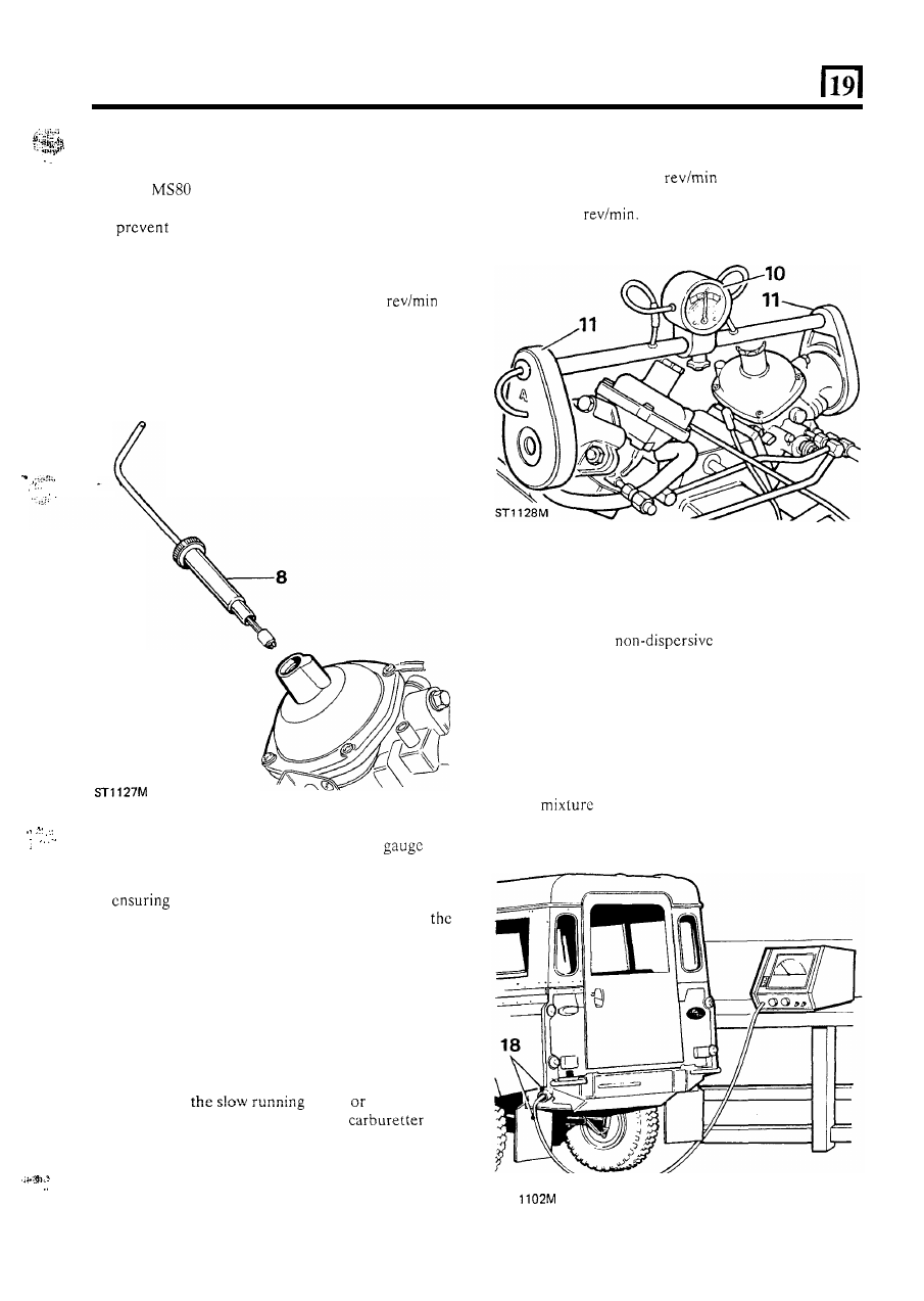
8.  Remove the piston  damper plug,  and  using special 

tool 

adjust  the  mixture.  Locate  the  outer 

sleeve  of  the  tool  to  engage  a  machined  slot  to 

the  air valve  twisting.  Turn  the  inner  tool 

clockwise 

to 

enrich the  mixture  and  anti-clockwise 

to  weaken  it.  After  every  adjustment  the  tool 

should  be  removed  from  the  carburetter  to  allow 
engine to stabilise.  Run  engine at 2000 

to 

aid stabilisation. 

9. 

When  t h e  mixture  is correctly  adjusted, the engine 

speed  will  remain  constant 

or 

may  fall  slowly  a 

small amount as the air valve is lifted. 

... 

..: 

... 

. .  

... 

10.  Check,  and  if  necessary,  zero  the 

on 

balancing 

tool 605330. 

11.  Place  balancer  on  the  carburetter  adaptors, 

that  there  are 

no 

air leaks.  If  the  engine 

stalls 

or  decreases  considerably  in  speed, 

mixture  is  too  rich. 

If 

t h e  

engine  speed  increases, 

the mixture is too weak. 

12.  If  necessary,  remove  balancer  and  re-adjust 

the 

mixture, then refit the tool. 

13.  Check balancer gauge reading. 

14. 

I f   the  gauge  pointer  is  in  the  ‘zero’  sector,  no 

adjustment is required. 

15. 

If  the  gauge  pointer  moves 

to 

t h e  

right,  decrease 

the 

air-flow  through  the  left-hand  carburetter  by 

air-flow  through  the  right-hand 

by 

turning clockwise  the slow running screw.  Reverse 
the 

procedure if the pointer moves to the left. 

16. 

If  the  engine  idle  speed  (slow  running)  rises  too 
high  or  drops  too  low  during  balancing  adjust  to 

the correct idle speed, whilst maintaining the gauge 
pointer in the zero sector. 

unscrewing 

screw 

increase 

the 

I... 

Check 

CO level 

Use  a proprietary 

infra-red  exhaust  gas 

analyser. 

18.  Insert  the  probe  of  the  analyser  as far  as  possible 

into  the  exhaust  tail  pipe,  start 

t h e  

engine  and 

allow  a  one to one and  a  half 

minute  stabilisation 

period. 

19.  Check that the correct idle speed  (slow running) is 

maintained  and  observe  the  C O   reading  against 
that given in the data section. 

If necessary re-adjust 

the 

setting to achieve the correct C O  level. 

ST 

13 

PETROL 

FUEL SYSTEM 

Adjust throttle linkage 

Fast idle adjustment 

20.  On  the  left-hand  carburetter,  place  a 

in) 

feeler  between  the  underside 

of  the 

roller  on  the  countershaft  lever  and  the  throttle 
lever. 

21.  Apply 

to  t h e   throttle  lever  to  hold 

the 

feeler. 

22.  Tighten  the  screw 

to 

secure  the  throttle  adjusting 

lever, then withdraw the feelcr. 

20 

26. 

The fast idle adjustment is  pre-set  on  the left-hand 
carburetter  and  should  not  normally  require 
adjustment.  If adjustment  is  required,  the  correct 
procedure  is 

to  remove  the  left-hand  carburetter 

and carry out instructions 

66 

69 under carburetter 

overhaul.  Alternatively  the  fast  idle  can  be 
approximately set  by  pulling  the choke  cable  until 
the mark 

on  the cam  is in-line with  t h e  head of  the 

adjusting screw. Slacken the locknut and adjust the 

screw against the cam until  the correct  idle speed 

is 

achieved  see  ‘Engine  tuning  data’.  Tighten  the 
locknut. 

23. 

On  the  right  hand 

place  a 

in) feeler between  the 

leg of  the fork on 

the  adjusting  lever  and  the  pin  o n   the  throttle 
lever. 

24.  Apply  light  pressure 

t o  

the  linkage  to  hold 

feeler. 

25.  Tighten  the  screw  to  secure  the  throttle  adjusting 

lever, then withdraw 

fcclcr. 

27. 

Fit t h e  air cleaner elbows. 

28.  Remove  the  piston  damper 

plug  on  both 

carburetters  and  replenish 

t h e  

damper  reservoir 

with  S.A.E.20 oil  to  within  12 

in)  from 

top of 

tube and refit  damper plug. 

14 

PETROL 

FUEL 

SYSTEM 

CARBURETTER OVERHAUL 

S.U. HIF 44 

Right hand 

DISMANTLE 

1.  Remove the carburetters from the engine and clean 

the exteriors with a suitable solvent. 

2.  Remove  the  two  nuts  and  spring  washers  and 

withdraw 

the air intake adaptor and joint washer. 

3.  Unscrew  and  remove 

piston  damper assembly 

and drain the oil. 

4.  Remove  the  three  screws  and  lift-off  the  suction 

chamber complete with piston and spring. 

5. 

Remove  the  spring clip from  the  top  of  t h e  piston 

rod and withdraw the piston  and spring. 

6.  Unscrew  the  fuel  metering  needle  guide  locking 

screw.  If 

needle  cannot  be  removed  from  the 

piston  with  the fingers, hold 

needle  as close to 

the piston  as possible, 

in a soft jawed  vice and with 

a sharp pull  withdraw  the needle, guide  and spring 

assembly. 

Remove 

four  screws  and  withdraw  the  float 

chamber cover plate and scaling ring. 

8.  Remove the jet adjusting lever retaining screw and 

spring. 

9.  Withdraw  the jet  complete  with  the bi-metal  lever 

and seperate the lever from the jet. 
Unscrew  and  remove 

float  pivot  spindle  and 

plain  washer, and remove the float. 
Lift-out the needle valve. 

12.  Unscrew and remove the needle valve and filter. 
13.  Unscrew and remove 

jet bearing nut. 

14.  Invert the carburetter body to allow the jet bearing 

to fall out. 

If  the bearing sticks, carefully  tap it out 

from t h e  bridge side. 

15.  Remove the piston  guide peg. 
16.  Remove 

t h e  

suction chamber-to-body sealing ring. 

17.  Unscrew  and  remove  the  mixture  adjusting  screw 

and seal. Use thin  nosed  pliers  to finally  withdraw 
the screw. 

18.  Bend-back 

t h e  

cam  lever 

n u t  

lock  tabs and remove 

the nut and lock washer. 

19.  Remove the cam lever and spring. 

20.  Remove the end seal cover and seal. 
21. 

Remove t h e  two screws and withdraw the cold start 

valve body and seal together with the valve spindle. 
Also collect the paper joint washer. 

22.  Note  t h e  position  of  the throttle  levers  and  return 

spring. 

Bend-back  the  lock  washer  tabs  and  remove  the 
throttle lever nut. 

24.  Remove 

the lock  washer, bush washer and throttle 

actuating lever. 

25. 

the 

spring 

and 

throttle  adjusting leaver from  the  throttle butterfly 
spindle and remove the return spring. 

26.  Hold the butterfly 

and mark the relationship 

of  the butterfly to the carburetter flange. 

27.  Remove  the  butterfly  two  retaining  screws  and 

withdraw the butterfly  from the spindle. 

28.  Withdraw  the  throttle  butterfly  spindle  from  the 

carburetter body together with  the two seals. 

29.  Clean  all  components  with  petrol  or  de-natured 

alcohol  ready  for  inspection. 

Do 

not  use  abrasives 

for the removal of stains or deposits. 

INSPECTION 

30.  Examine  the  throttle  spindle  and  bearings  for 

excessive axial clearance. 

31.  Check the float needle and seating for wear and the 

float for punctures and renew if necessary. 

32.  Check  the  condition  of  all  rubber  seals, 

‘0’ 

rings 

and joint washers and renew 

if necessary. The float 

cover plate seal must be renewed. 

33.  Examine  the  carburetter  body  for  cracks  and 

damage. 

34.  Ensure  that  the  inside 

of  the  suction  chamber 

is 

clean  and 

fit 

piston  into the  chamber  without 

the spring. Hold t h e  assembly horizontally  and spin 
the  piston. 

The  piston  should  spin  freely 

in  the 

suction chamber without any tendency to stick. 

35.  Inspect  the  metering  needle  for  wear, scores  and 

distortion.  Check  also  that 

it 

has  the  correct 

designation  number 

Engine  Tuning  Data, 

Section 

05. 

36.  Examine the bi-metal jet  lever for cracks. 
37.  Check all springs for cracks and distortion. 

ASSEMBLE 

Fit throttle butterfly 

38.  Fit  the throttle spindle 

to 

t h e  

carburetter body  and 

insert the throttle disc into 

spindle in its original 

position.  Secure  the  disc  with  new  screws  and 
ensure  that  before  tightening  the  throttle  disc  is 
correctly  positioned  and closes properly.  Splay the 
split ends of the screws to prevent turning. 

39. 

Fit  new  seals  to  both  ends of  t h e   throttle  spindle 

ensuring that they are fitted the correct way round. 

Fit 

cold start assembly 

40. 

Fit  a  new 

ring  to  the  valve  body  and  assemble 

t h e  

valve spindle 

to 

the valve body. 

43 

41. 

Fit 

a  new  paper  j o i n t   washer  to  the  valve  noting 

that  the  half-moon  cut-out 

in 

the  washer  is 

clearance for the top retaining screw. 

continued 

15 

PETROL FUEL 

SYSTEM 

42.  Fit the starter assembly to the carburetter body and 

secure with the two screws. 

43. 

Fit the end seal and cover. 

44.  Fit the return spring. 
45.  Fit  the cam  lever and  tension  the spring. 

Fit  a new 

lock  washer and secure with  the  nut  and  bend  the 
tabs over a convenient flat. 

46.  Adjust  the  coils  of  the  spring,  if  necessary,  to 

prevent coil binding. 

45 

KEY TO 

S.U. 

COMPONENTS 

1. 

2. 
3. 
4. 
5. 
6. 

7. 
8. 
9. 

11. 

12. 

14. 
15. 
16. 
17. 

18. 
19. 

20. 
21. 
22. 
23. 

24 

25. 
26. 
27. 
28. 
29. 
30. 
31. 

16 

Piston damper. 
Spring clip. 
Suction chamber. 

Piston. 

Piston spring. 
Suction chamber retaining screws -3 

off. 

Needle retaining screw. 
Needle bias spring. 
Needle guide. 
Needle. 
Suction chamber sealing ring. 

Throttle adjusting scrcw and scal. 

Piston  key and retaining screw. 
Mixture adjusting screw and seal. 
Carburetter body. 

Throttle butterfly and retaining screws. 
Throttle spindle. 
Throttle spindle 

2 off. 

Float chamber. 
Float chamber cover and retaining 
Float chamber cover seal. 

Jet 

Jet bearing. 

bearing 

n u t  

Bi-metal jet lever. 

Jet retaining and adjusting screw and spring. 
Float needle. 
Float needle seat. 
Float needle seat filter. 
Float 
Float pivot spindle. 

32.  Cold start and cam lever assembly. 
33.  Throttle adjusting lever and lost motion  assembly. 
34.  Throttle actuating lever. 
35.  Bush washer. 
36.  Throttle  lever  assembly  retaining  nut  and  lock 

washer. 

continued 

... 

... 


Content   ..  53  54  55  56   ..