Defender 90 / 110 / 130. Manual - part 29


  Index      Land Rover     Defender 90 / 110 / 130 - service repair manual


Search            


Content   ..  27  28  29  30   ..


Defender 90 / 110 / 130. Manual - part 29


2.25 

LITRE PETROL AND DIESEL CYLINDER  HEAD 

. . .  

EXAMINATION OF COMPONENTS 

Petrol engine 

32.  Examine 

t h e  

cylinder  head 

cracks  and 

distortion. Burnt, pitted  and  pocketed  seats  must 
be repaired. 

Diesel engine 

33.  Same as for petrol engine and  in addition, worn  or 

damaged  exhaust  seat  inserts should  be  renewed, 
as described later. 

Hot 

and 

injector shrouds 

examine and 

renew 

When  carrying 

out  normal  top  overhaul  work  on  the 

cylinder  head 

i t  

is  not  necessary  to 

either  the 

injector shrouds o r  

hot plugs. 

Small surface cracks 

in  the hot plug, extending from  the 

opening  to  approximately 

i n )  

in 

length 

can be ignored. However  any severe 

appear on 

the face 

of  the hot  plug, before attempting to remove 

i t ,  

closely  inspect  t h e   cylinder  head  for 

signs 

of  cracks, 

particularly  between  the  inlet  and  exhaust  valve  seats. 
Such cracking indicates that  the engine has overheated, 
usually  through  lack  o f   coolant,  and  the  cylinder  head 

scrapped. 

. .  

34. 

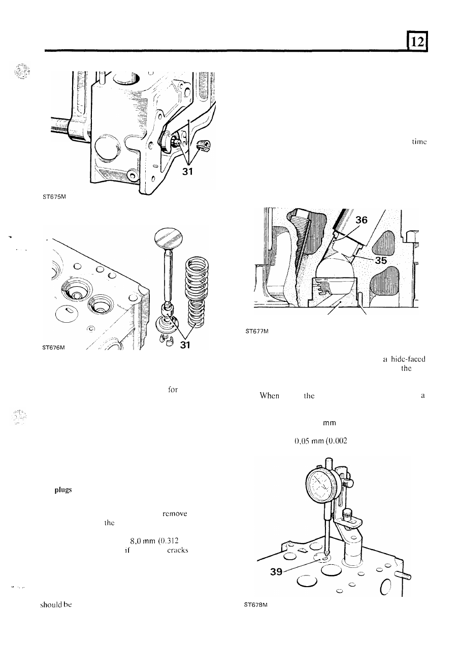
To remove a hot plug, insert 

a thin soft metal drift 

through  the injector shroud throat and tap the 

hot 

plug  from  the  inside.  Once  removed  a faulty  hot 
plug cannot be restored and must  be renewed. 

35.  I f  the injector shroud is damaged, drift the shroud 

out towards the injector bore. 

36.  Thoroughly  clean  out  the  combustion  chamber. 

The 

hole  in  the  side  of  the  injector  shroud  is  for 

manufacturing  purposes only but  at the same 
can be used as a guide when refitting the shroud. 

37.  Smear a little oil on  t h e  shroud and insert into the 

cylinder  head  with  the 

hole  pointing  towards  the 

centre 

of  t h e   cylinder  head,  and  drift  into 

position. 

34 

38 

38.  Fit  the  hot  plugs  by  tapping 

with 

mallet,  and  locate  with  a  new  roll  pin. 

If 

hot 

plugs  are  loose 

in  the  cylinder head  they  may  be 

retained 

with 

a little grease. 

39. 

fitted, 

hot  plugs must  be checked with 

dial  test  indicator  to  ensure  that  they 

do 

not 

protrude above the level 

of  the cylinder  head  Cace 

more  than 

0,025 

(0.001 

in)  and  are  not 

recessed  below  the  level  of  the cylinder  head  face 
more than 

i n ) .  

35 

2.25 LITRE PETROL AND DIESEL CYLINDER HEAD 

Petrol and diesel engines 

40.  Chcck  the  valve  guides  for  wear  by  inserting  a 

new  valve 

in  the  appropriate guide 

above 

the  seat.  If  movement  across  the  head  exceeds 

(0.006 in) renew the guide. 

41.  Inspect the valves and discard any that are burnt, 

bent 

or  distorted.  Check  the  stems  for  wear  by 

inserting  in  a  new  guide.  If  wear  is 
discard  the  valve.  Valve  faces  that  are  pitted  o r  
ridged but otherwise serviceable may be refaced. 

42.  Renew  push  rods  that  are  bent 

or  have  worn 

or 

scored ball 

or socket ends. 

Renew 

push rod 

tube seals (Diesel only) 

43.  Whilst  this  is  rarely  necessary  the  procedure  is 

44.  Drive  out the old  push  rod  tubes  using  a suitable 

nevertheless as follows. 

drift. 

NOTE: Later engines are fitted with tubes without seals. 
See 2.5 litre Diesel engine 

for renewal. 

45.  Fit  new  sealing rings  to  new  push  rod  tubes  and 

smear with silicone MS4 grease. 

46.  Insert the new tubes, chamfered end first from 

t h e  

combustion  chamber  side.  Align  t h e   flat  on  the 
push  rod  tube at right  angles to an  imaginary  line 
between  the  centre 

of  the  push  rod  tube  and 

centre of the hot plug. 

47.  Press  the  push 

rod  tubes  into  position  whilst 

maintaining  the  alignment. 

Also  ensure  that  the 

chamfers 

on the tubes and in the cylinder head are 

fully engaged. 

Renew valve guide 

48.  Support  the  cylinder  head,  combustion  chamber 

uppermost  on  pieces  of  timber  of  sufficient 
thickness 

to  allow  clearance 

for  the  valve  guides 

to be driven out. 

Using  special  drift  274400 

for  inlet  guides  and 

274401  for exhaust 

or suitable alternatives 

drive 

out the old guides from the combustion  face 

side. 

NOTE:  The  illustration  shows 

a  petrol  engine 

cylinder head. 

36 

,. 

.  . 

2.25 

LITRE PETROL AND DIESEL CYLINDER HEAD 

.,. 

I .  

50. 

Turn 

the  cylinder  head  over 

so  the  combustion 

chambers  face  downwards.  Since  the 

inlet  and 

exhaust valve guides are dimensionally different it 
is  important  that  the  correct  guides  are  fitted  to 

the appropriate ports. 

51. 

Lubricate  new  guides  with  engine 

oil  and  using 

special drift 600959 for the exhaust and 601508 for 
the 

valve  guides 

or  suitable  alternatives, 

drive 

in 

new  guides until  the  shoulder 

is 

flush 

with the casting. 

53.  The  special  set  of hand  tools  recommended 

for 

refacing  include  expandable  pilots  that  fit  tightly 
into new 

or worn  guides to ensure  that  the  valve 

seat  is  concentric  with  valve  guide. 

The  refacing 

tool  has  tungsten  carbide cutters and can  be  used 
to cut 

a seat in a new exhaust seat insert. 

54.  Select the correct  expandable  collet  for  the  valve 

guide  concerned 

i.e. 

for  inlet  guides  and 

for exhaust. 

55. 

Loosely  assemble  the  collet,  expander  and  nuts. 

Ensure  that  the chamfered end of  the expander is 
towards the collet. 

Reface cylinder head valve seats 

52.  Damaged  or  worn  valve  seats  can  be  refaced 

provided  they  are  not  abnormally  wide  due  to 
repeated refacing operations. 

instruction 64. 

56.  Insert  the  assembled  pilot  into  the  valve  guide 

from  the  combustion  face  side  of  the  cylinder 

head  until  the  shoulder  contacts 

valve 

and  the  whole  of  the  collet  is  inside  the  valve 

guide. 

57.  Expand  the  collet  in  the  guide  by  turning  the 

bar  clockwise  whilst  holding 

knurled 

nut. 

58. 

Select  t h e  appropriate angled  cutter for the  seats 
to be cut. 

continued 

Correctly seated valve 

Undesirable condition 

C. Method 

of rectification 

37 

2.25 LITRE PETROL AND DIESEL CYLINDER HEAD 

NOTE:  MS  621  is  a  45"  and  15"  cutter  and  MS  627 
is 30" only. 

- Petrol engine 

inlet valve seat 30" 

Diesel engine 

inlet 

valve seat 

45" 

exhaust valve seat 45" 

exhaust valve seat 45" 

See illustrations following instruction 

68. 

59.  Ensure  that  the  cutter blades  are  correctly  fitted 

to the 

head with the angled end 

of  the blade 

downwards facing  the work, as illustrated.  Check 
that  the  cutter  blades  are  adjusted  so  that  the 
middle 

the  blade  contacts the 

of  material 

to  be  cut.  Use  the  key  provided 

i n   the  hand  set 

MS 76. 

60. 

Fit  the  wrench  to  the  cutter  head  and  turn 

clockwise using  only very light pressure. Continue 
cutting to approximately the centre of  the existing 
seat. 

61.  T o   check.  the  effectiveness  of 

cutting 

operation  use  engineers'  blue  or  a  feeler  gauge 
made from cellophane. 

38 

62.  Smear a 

quantity 

of  engineers'  blue  round 

the valve seat and revolve 

a properly ground valve 

-- 

..... 

against  the  seat. 

continuous 

fine  line  should 

appear  round  the  valve. 

If 

there  is  a  gap 

of  not 

more than  12 

i t  

can  be corrected by lapping. 

63.  Alternatively,  insert a strip ofcellophanc between 

the  valve  and  seat,  hold  the  valve  down  by  the 
stem and slowly pull  out 

t h e  

cellophane. 

If there is 

a drag the seal  is satisfactory 

in  that  spot. Repeat 

this 

in 

at least eight places.  Lapping-in 

will 

correct 

a small open spot. 

64.  After  several  trueing-up o r  

operations 

valve seats may  have an excessive width  which can 
be reduced  by  obtaining special  correction cutters 
which narrow t h e  seat by  removing metal from the 
top  and  bottom  of  the  scat. 

60"  cutter  is 

recommended  for  bottom  narrowing  and 

for 

top 

narrowing use a 

cutter 

(MS 621) for a 30" valve 

seat  and  a  30"  cutter  for  a  45"  seat.  The 

correction  cutters as 

for refacing cutters. 

very 

light  pressure  removing  only  the 
material  necessary.  Once  the  seats  have  been 
reduced  carry  out  the  normal  refacing  operation 

as previously described. 

of  assembly  and  operation  is  used  for- 

Renew 

exhaust seat 

inserts 

(Diesel only) 

65.  Hold  the  cylinder  head 

in  a  vice,  wear 

protective  goggles  and  grind  the  old  insert 

until 

thin 

enough 

to 

be  cracked  and  prised  out. 

Take care not to damage 

insert pocket. 

66.  Remove  any  burrs  and  swarf  from  the  pocket. 

Failure  to  do  this  could  cause  the  new  insert  to 
crack when being fitted. 

67.  Assemble  the  new  insert  to  the  replacer  tool 

number 530625 

so that  the chamfered edge 

of 

the 

insert  is 

Using 

suitable  bolt  and 

n u t  

draw 

insert into the cylinder head pocket. 

Cut  new 

seat using cutter 

MS 621. 


Content   ..  27  28  29  30   ..