Defender 90 / 110 / 130. Manual - part 28
2.25
LITRE PETROL AND
DIESEL ENGINE
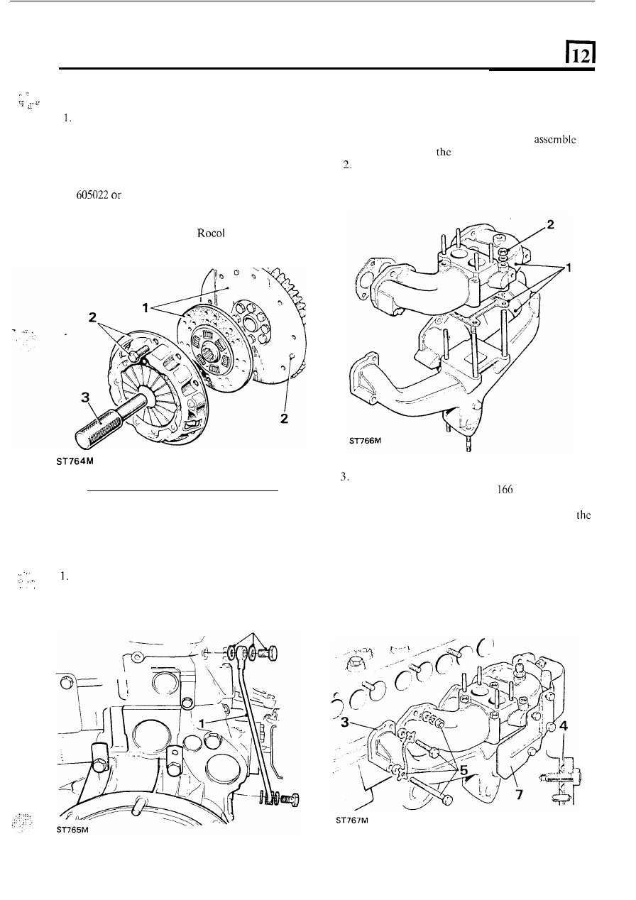
FIT THE CLUTCH
Clean the flywheel face and place the centre plate
with the side marked ‘Flywheel side’ towards the
flywheel.
2 . Fit the clutch assembly locating
i t
over the three
dowels and loosely secure with the six bolts.
3. Centralise the centre plate using special
tool
RO
a spare primary shaft and tighten the six
bolts evenly to t h e correct torque figure. Smear the
splines of the centre plate with Molybdenum
disulphide grease, such as
MTS 1000.
FIT INLET AND EXHAUST MANIFOLDS
Petrol engine
1. Using a new ‘hot spot’ joint washer
the
inlet manifold
to
exhaust manifold.
Secure with the four nuts and evenly tighten to the
correct torque,
t h e n slacken
off but retain the ‘nip’
of the four nuts.
Coat the face of the exhaust manifold with Rocol
anti-seize compound Foliac J
(paste)
and the
corresponding face
of the cylinder head.
4.
Fit
t h e
joint washcrs of inlet manifold
with
raised rings towards the cylinder head.
5 .
Fit and tighten the securing nuts and bolts to the
correct torque including the two common bolts and
clamps. Note the two outer bolts at both ends of
the exhaust manifold have lock plates.
6. Finally tighten the f o u r
‘hot
spot’ joint nuts cvcnly
to correct torque.
7.
Fit the heat shield.
FIT CYLINDER HEAD OIL FEED
. .
...
.
.
Connect the oil feed pipe,
for lubrication of the
2. Secure with the two banjo bolts and f o u r joint
rocker shaft assembly, to the cylinder head.
washers.
2
31