Defender 90 / 110 / 130. Manual - part 30


  Index      Land Rover     Defender 90 / 110 / 130 - service repair manual


Search            


Content   ..  28  29  30  31   ..


Defender 90 / 110 / 130. Manual - part 30


2.25 

LITRE PETROL AND DIESEL CYLINDER 

HEAD 

Reface valve faces 

68.  Valves that  are satisfactory for further service can 

be 

This operation  should  be  carried 

out 

using  a  valve  grinding  machine.  Only 
minimum  of  material should bc 

from the 

valve  face 

to 

avoid thinning of the valve  edge. 

The 

valve  is  refaced  correctly  when  all  pits  are 
removed and the face concentric with the stem. 
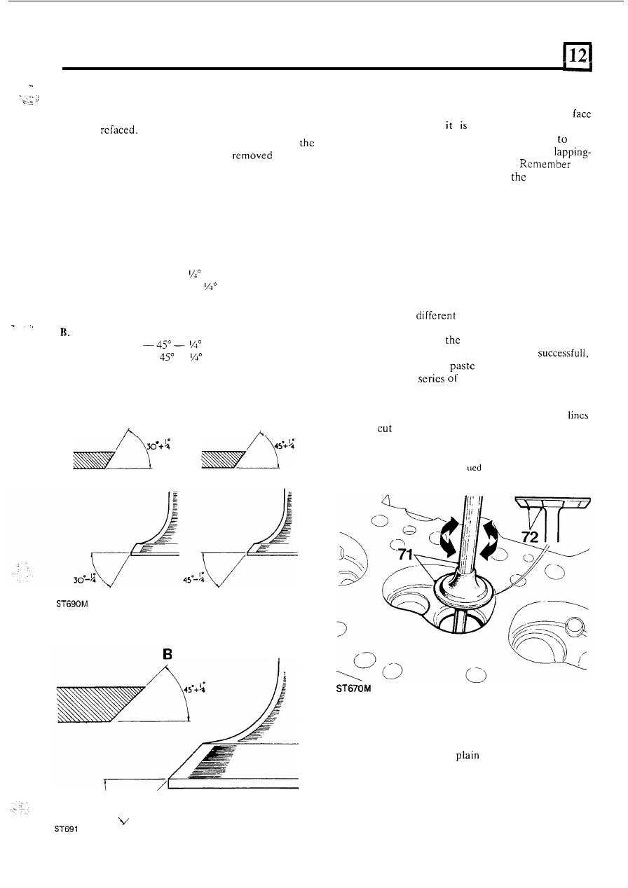
Valve face angles: 

A .  

Petrol engine 
Inlet valve face 

30" 

Exhaust valve  face 

45" 

Diesel engine 
Inlet valve face 
Exhaust valve face 

Lap-in valves 

69. 

To ensure  a gas tight  seal between  the valve 
and  valve  scat 

necessary  to  lap-in  the 

appropriate valve 

to 

its seat. 

It 

is essential 

keep 

the valve  identified with  its seat once the 

in operation  has been completed. 

that 

the  inlet  and  exhaust  valves 

in 

petrol  engine 

have different face angles. 

70.  Unless  the  faces  to  be  lapped  are 

in 

poor 

condition 

it 

should  only  be  necessary  to 

use  fine 

valve  lapping  paste.  Smear  a  small  quantity  of 
paste 

on  the  valve  face  and  lubricate  the  valve 

stem with engine oil. 

71.  Insert the valve in the appropriate guide and using 

a  suction  type  valve  lapping  tool  employ 

a  light 

reciprocating  action  while  occasionally  lifting  the 

valve  off  its  seat  and  turning 

it 

so  that  the  valve 

returns 

to 

position on 

t h e  

seat. 

72.  Continue  the  operation  until  a  continuous  matt 

grey  band  round 

valve  face  is  obtained. 

To 

check  that  the  lapping  operation  is 
wipe 

off the  valve 

from  the  valve  and  scat 

and  make 

pencil  lines  across  the valve 

face.  Inset  the  valve  into  the  guide  and  while 
pressing  the valve  onto the seat revolve  the  valve 
a  quarter turn  a  few  times.  If  all  the  pencil 
are 

through  no further lapping is required. 

73.  Wash  all  traces of  grinding  paste  from  the  valves 

and cylinder head seats. 

con 

tin 

Assemble valves 

to 

cylinder head 

74.  Insert  the  inlet  valves  into the guides and  fit  new 

oii  seais 

with 

the 

exterior  and  circuiar 

spring.  Ensure that  t h e  seal  locates 

in  the groove 

in t h e  valve guide. 

75.  Insert  the exhaust valves  and fit  the oil  seals 

with 

the ridged exterior and n o  spring. 

continued 

39 

2.25 LITRE PETROL AND DIESEL CYLINDER HEAD 

76. 

Fit  the double valve  spring and retainer assembly 
to  each  valve  in  turn  and  using  valve  spring 

compressor, 

with  adaptor 

secure the assembly with the split 

74 

ST6 

7 5  

Examine  the  rocker  shaft 

for wear  and  discard 

i f  

ST 

80 

OVERHAUL ROCKER 

SHAFT ASSEMBLY 

Most 

of 

rocker shaft assembly components are not 

interchangeable  between  the petrol  and  diesel  engines 
although the assembly method is the same. 

Dismantle and inspection 

77.  Remove  the  locating screw  and  washer  from  the 

number  two  rocker  bracket  and  withdraw  all  the 
components  from  the  rocker  shaft.  Note  that 

on 

the petrol  engine the locating screw  also retains  a 
splash plate. 

78.  Remove the locknuts and adjustment screws from 

the rockers. 

40 

the  bearing 

is  worn  more  than  0,025 

(0.001 

i n ) .  

Inspect 

rockers  and  discard  if  the  pads 

are 

worn.  It  is  not  permissible 

to 

grind  pads 

in  an 

attempt to reclaim the rockers. 

Renew  bushes  if  the clearance between  shaft  and 

bush  is 

in 

excess  of 

to  0,127 

(0.004 to 

0.005 in). 
Press 

in 

replacements ensuring that 

pre-drilled 

oil holes coincide 

with 

the 

in the rockcrs. 

Illustration  A .  

Cross  section  of  petrol  engine 

rocker. 
Illustration 

Cross  section 

of  diesel  engine 

rocker. 

81.  Using  a  reamer  finish  the  bushes  to 

(0.530 

in 

0.001 in)  and  clear  swarf 

from the oil holes. 

82.  Examine  the 

of 

t h e  

adjusting screws and 

discard  any  that  are  worn.  Regrinding  is  not 
permissible.  Check  the  threads  for  damage  and 
that 

t h e  

oil relief  drilling is clear. 

2.25 LITRE PETROL AND DIESEL CYLINDER HEAD 

Assemble rocker shaft assembly 

.... 

83. 

Check  that  the  oil-ways 

in  the  rocker  shaft  are 

clear  and 

fit 

number  two  rocker  shaft  bracket 

to 

the  shaft  and  retain  with  the  locating  screw  and 
washer.  Note  that 

the  locating  screw  on  petrol 

engines also secures the splash plate. 

84.  Using  new  spaccrs  and  springs,  assemble  the 

rockers  and  brackets  to  the  shaft  as  illustrated, 
ensuring that the rockers move freely 

on the shaft. 

Note  that  the Diesel  engine assembly  has  double 
spacers each side of  the centre pedestal. 

Illustration 

C. Petrol engine assembly. 

Illustration 

Diesel engine assembly 

85.  Fit 

tappet  adjustment screws and 

lock  nuts to 

Invert  the  rocker  assembly  and  locate 

it 

on  the 

the 

rocker cover to prevent 

i t  

falling apart. 

continued 

41 

2.25 LITRE PETROL AND DIESEL CYLINDER HEAD 

92.  Adjust the tappet clearances for petrol  and diesel 

engines,  inlet  and  exhaust 

to 

(0.010  in) 

Fit the cylinder head 

as  follows:  Using  a  feeler  gauge  adjust  the 

87. 

the cylinder head and cylinder block mating 

clearance  by  slackening  the  locknut  and  turning 

faces and fit a new  gasket, dry, without  grease or 

the  tappet  adjusting  scrcw  clockwise 

to  reduce 

compound.  The  gasket 

will 

either 

clearance 

and 

anti-clockwise 

to 

increase 

'DIESEL' 

or 

'PETROL'  stamped in  the  position 

clearance. 

illustrated and the gasket must be fitted with these 
uppermost. 

88.  Place the cylinder head  in position  and  engage all 

Set 

N o .   tappet 

with 

No. 8 valve  fully open. 

the  cylinder  head  bolts  and  washers  except  those 

Set 

No. 3 tappet 

with 

No. 

6 valve fully open. 

used  to secure the rocker assembly. Use new bolts 

Set 

No. tappet 

with 

N o .  4 

valve fully open. 

and ensure that the correct bolts 

for the petrol and 

Set 

No. 2 tappet 

with 

No. 

7 valve fully open. 

diesel 

engine 

are 

fitted. 

They 

are 

not 

Set 

No. 

tappet with N o .  1 valve fully open. 

interchangeable. 

Set 

N o .  

tappet with 

No. 3 valve fully open. 

Set 

No. 4 tappet 

with 

N o .  valve 

fully 

open. 

Set 

N o .  7 tappet 

with 

No. 2 valve fully open. 

93.  Recheck  the  clearances  with  the  locknuts 

tightened  and adjust 

as necessary. 

89.  Insert  the  push  rods  into  position  ensuring  that 

the  ball-ends  fit  correctly  into  the  spherical seats 

i n  

the tappet slides. 

Fit  the  rocker  shaft  assembly  ensuring  that  the 
hole 

in  the  front  and  rear  rocker  bracket  locates 

properly 

in 

the  corresponding  dowel 

in  the 

cylinder  head.  Also, make 

that 

ball-end 

of  all  the rockers f i t   into the spherical  seats of  the 
push  rods.  Evenly  tighten  the  rocker  shaft 
retaining bolts 

to the correct torque. 

91.  Tighten  the  cylindcr  head  and  rocker  shaft 

securing  nuts  and  bolts  strictly 

in  the  sequence 

illustrated 

to 

avoid distortion of  the cylinder head. 

Tighten 

to  the  torque  figures  given  in  the  data 

section. 

The  arrow  points 

to  the  front  of  the 

engine 


Content   ..  28  29  30  31   ..