Jeep Wrangler TJ. Manual - part 509


  Index      Jeep     Jeep Wrangler TJ - service repair manual 2005 year


Search            


Content   ..  507  508  509  510   ..


Jeep Wrangler TJ. Manual - part 509


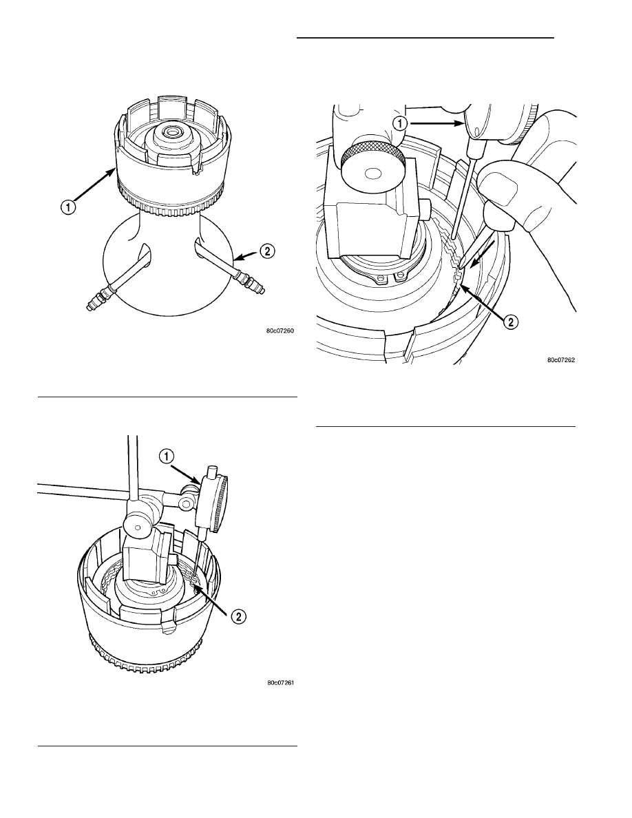
(18) Install input clutch assembly (1) to the Input

Clutch Pressure Fixture 8391 (2) (Fig. 202).

(19) Set up dial indicator (1) on the UD clutch

pack (2) (Fig. 203).

(20) Using moderate pressure, press down and

hold (near indicator) the UD clutch pack (2) with
screwdriver or suitable tool and zero dial indicator
(1) (Fig. 204). When releasing pressure on clutch
pack, indicator reading should advance 0.005-0.010
inches.

CAUTION: Do not apply more than 30 psi (206 kPa)
to the underdrive clutch pack.

(21) Apply 30 psi (206 kPa) to the underdrive hose

on Tool 8391 and measure UD clutch clearance. Mea-
sure and record UD clutch pack measurement in four
(4) places, 90° apart.

(22) Take average of four measurements and com-

pare with UD clutch pack clearance specification.
Underdrive clutch pack clearance must be 0.94-
1.50 mm (0.037-0.059 in.).

(23) If necessary, select the proper reaction plate

to achieve specifications.

(24) Install the OD clutch pack (four fibers/three

steels) (1) (Fig. 205).

(25) Install OD reaction plate waved snap ring (1)

(Fig. 206).

(26) Install the OD/Reverse reaction plate (1) with

large step down (towards OD clutch pack) (Fig. 207).

(27) Install OD reaction plate flat snap ring (3)

(Fig. 208).

Fig. 202 Input Clutch Assembly on Pressure Fixture

Tool - 8391

1 - INPUT CLUTCH ASSEMBLY
2 - INPUT CLUTCH PRESSURE FIXTURE - 8391

Fig. 203 Set Up Dial Indicator to Measure UD Clutch

Clearance

1 - DIAL INDICATOR
2 - UNDERDRIVE CLUTCH

Fig. 204 Press Down on UD Clutch Pack and Zero

Dial Indicator

1 - DIAL INDICATOR
2 - UNDERDRIVE CLUTCH

21 - 126

AUTOMATIC TRANSMISSION - 42RLE

TJ

INPUT CLUTCH ASSEMBLY (Continued)

(28) Measure OD clutch pack clearance. Set up

dial indicator (1) on top of the OD/Reverse reaction
plate (2) (Fig. 209).

(29) Zero dial indicator and apply 30 psi (206 kPa)

air pressure to the overdrive clutch hose on Tool
8391. Measure and record OD clutch pack measure-
ment in four (4) places, 90° apart.

(30) Take average of four measurements and com-

pare with OD clutch pack clearance specification.
The overdrive (OD) clutch pack clearance is
1.07-3.25 mm (0.042-0.128 in.).

Fig. 205 Install OD Clutch Pack

1 - OVERDRIVE CLUTCH PACK

Fig. 206 Install Waved Snap Ring

1 - OVERDRIVE REACTION PLATE WAVED SNAP RING
2 - SCREWDRIVER

Fig. 207 OD/Reverse Reaction Plate

1 - OVERDRIVE/REVERSE PRESSURE PLATE
2 - (STEP SIDE DOWN)

Fig. 208 Install Flat Snap Ring

1 - ARBOR PRESS RAM
2 - TOOL 5059A
3 - FLAT SNAP RING

Fig. 209 Measure OD Clutch Pack Clearance

1 - DIAL INDICATOR
2 - OD/REVERSE PRESSURE PLATE

TJ

AUTOMATIC TRANSMISSION - 42RLE

21 - 127

INPUT CLUTCH ASSEMBLY (Continued)

If not within specifications, the clutch is not

assembled properly. There is no adjustment for the
OD clutch clearance.

(31) Install reverse clutch pack (two fibers/one

steel) (1, 2) (Fig. 210).

(32) Install reverse clutch reaction plate (1) with

the flat side down towards reverse clutch (Fig. 211).

(33) Tap reaction plate (3) down to allow installa-

tion of the reverse clutch snap ring (1). Install
reverse clutch snap ring (1) (Fig. 212).

(34) Pry up reverse reaction plate (4) to seat

against snap ring (2) (Fig. 213).

Fig. 210 Install Reverse Clutch Pack

1 - REVERSE CLUTCH PLATE
2 - REVERSE CLUTCH DISCS

Fig. 211 Install Reaction Plate

1 - REVERSE CLUTCH REACTION PLATE (FLAT SIDE DOWN)

Fig. 212 Install Reverse Clutch Snap Ring

1 - REVERSE CLUTCH SNAP RING (SELECT)
2 - SCREWDRIVER
3 - REVERSE CLUTCH REACTION PLATE

Fig. 213 Pry Up Reaction Plate

1 - SCREWDRIVER
2 - SNAP RING
3 - SCREWDRIVER
4 - MUST RAISE REVERSE REACTION PLATE TO RAISE SNAP
RING

21 - 128

AUTOMATIC TRANSMISSION - 42RLE

TJ

INPUT CLUTCH ASSEMBLY (Continued)

(35) Set up a dial indicator (1) on the reverse

clutch pack (2) (Fig. 214).

(36) Using moderate pressure, press down and

hold (near indicator) reverse clutch disc (2) with
screwdriver or suitable tool and zero dial indicator
(1) (Fig. 215). When releasing pressure, indicator
should advance 0.005-0.010 inches as clutch pack
relaxes.

(37) Apply 30 psi (206 kPa) air pressure to the

reverse clutch hose on Tool 8391. Measure and record
reverse clutch pack measurement in four (4) places,
90° apart.

(38) Take average of four measurements and com-

pare with reverse clutch pack clearance specification.
The reverse clutch pack clearance is 0.89-1.37
mm (0.035-0.054 in.). 
Select the proper reverse
clutch snap ring to achieve specifications.

(39) To complete the assembly, reverse clutch and

overdrive clutch must be removed.

(40) Install the number 2 needle bearing (1) (Fig.

216).

Fig. 214 Measure Reverse Clutch Pack Clearance

1 - DIAL INDICATOR
2 - REVERSE CLUTCH

Fig. 215 Press Down on Reverse Clutch and Zero

Indicator

1 - DIAL INDICATOR
2 - REVERSE CLUTCH

Fig. 216 Install No. 2 Needle Bearing

1 - #2 NEEDLE BEARING (NOTE 3 SMALL TABS)
2 - TABS UP

TJ

AUTOMATIC TRANSMISSION - 42RLE

21 - 129

INPUT CLUTCH ASSEMBLY (Continued)


Content   ..  507  508  509  510   ..