Jeep Wrangler TJ. Manual - part 477


  Index      Jeep     Jeep Wrangler TJ - service repair manual 2005 year


Search            


Content   ..  475  476  477  478   ..


Jeep Wrangler TJ. Manual - part 477


When steering pump pressure exceeds 5860 kPa ±

690 kPa (850 psi ± 100 psi), the normally closed
switch will open and the PCM will increase the
engine idle speed. This will prevent the engine from
stalling.

When pump pressure drops to approximately 1379

kPa (200 psi), the switch circuit will re-close and
engine idle speed will return to its previous setting.

REMOVAL

This switch is not used with 4.0L six-cylinder

engines.

The power steering pressure switch is installed in

the power steering high-pressure hose (Fig. 5).

(1) Disconnect electrical connector from power

steering pressure switch.

(2) Place a small container or shop towel beneath

switch to collect any excess fluid.

(3) Remove switch. Use back-up wrench on power

steering line to prevent line bending.

INSTALLATION

This switch is not used with 4.0L six-cylinder

engines.

(1) Install power steering switch into power steer-

ing line.

(2) Tighten to 14–22 N·m (124–195 in. lbs.) torque.
(3) Connect electrical connector to switch.
(4) Check power steering fluid and add as neces-

sary.

(5) Start engine and again check power steering

fluid. Add fluid if necessary.

PULLEY

REMOVAL

CAUTION: On vehicles equipped with the 4.0L, Do
not reuse the old power steering pump pulley it is
not intended for reuse. A new pulley must be
installed if removed.

(1) Remove pump assembly.
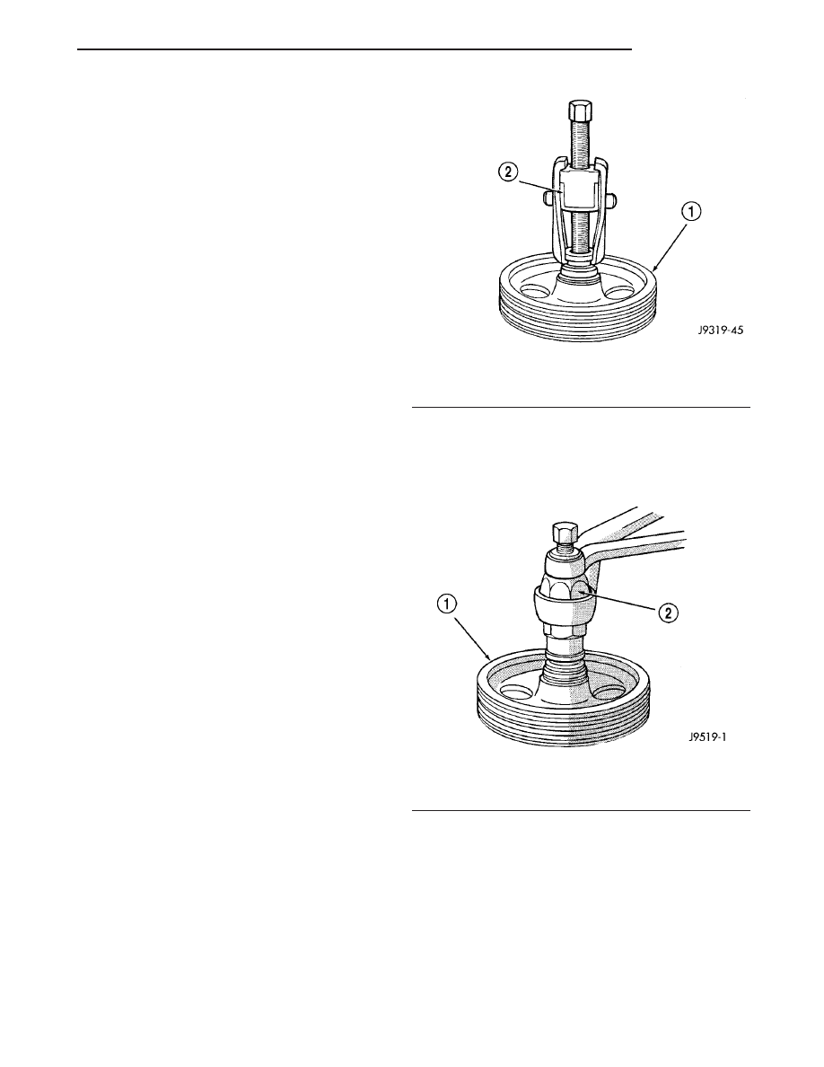
(2) Remove pulley from pump with Puller C-4333

or equivalent puller (Fig. 6).

INSTALLATION

NOTE: The pulley is marked front for installation.

CAUTION: On vehicles equipped with the 4.0L, Do
not reuse the old power steering pump pulley it is
not intended for reuse. A new pulley must be
installed if removed.

(1) Replace pulley if bent, cracked, or loose.
(2) Install pulley on pump with Installer C-4063-B

or equivalent installer (Fig. 7). The pulley must be
flush with the end of the shaft. Ensure the tool and
pulley are aligned with the pump shaft.

(3) Install pump assembly.
(4) With Serpentine Belt, run engine until warm (5

min.) and note any belt chirp. If chirp exists, move
pulley outward approximately 0.5 mm (0.020 in.). If
noise increases, press on 1.0 mm (0.040 in.). Be
careful that pulley does not contact mounting
bolts.

Fig. 6 Pulley Removal

1 - POWER STEERING PUMP DRIVE PULLEY
2 - SPECIAL TOOL C-4333

Fig. 7 Pulley Installation

1- POWER STEERING PUMP DRIVE PULLEY
2 - SPECIAL TOOL C-4063-B

TJ

PUMP

19 - 25

POWER STEERING PRESSURE SWITCH (Continued)

RESERVOIR

REMOVAL

REMOVAL - 4.0L

(1) Remove power steering pump. (Refer to 19 -

STEERING/PUMP - REMOVAL).

(2) Clean exterior of pump.
(3) Clamp the pump body in a soft jaw vice.
(4) Pry up tab and slide the retaining clips off

(Fig. 8).

NOTE: Use new retaining clips for installation.

(5) Remove

fluid

reservoir

from

pump

body.

Remove and discard O-ring seal.

REMOVAL - 2.4L

(1) Remove the pump return hoses from the reser-

voir and drain the reservoir.

(2) Remove the push-in fastener from the reservoir

(Fig. 9).

(3) Slide the reservoir up out of the fan shroud

mount.

INSTALLATION

INSTALLATION - 4.0L

(1) Lubricate new O-ring Seal with Mopar Power

Steering Fluid or equivalent.

(2) Install O-ring seal in housing.
(3) Install reservoir onto housing.
(4) Slide and tap in new reservoir retainer clips

until tab locks to housing.

(5) Install power steering pump. (Refer to 19 -

STEERING/PUMP - INSTALLATION).

(6) Add power steering fluid, (Refer to 19 -

STEERING/PUMP - STANDARD PROCEDURE).

INSTALLATION - 2.4L

(1) Slide reservoir down onto the fan shroud

mount until it clicks in place.

(2) Install the push-in fastener.
(3) Install the hoses.
(4) Fill reservoir to proper level, (Refer to 19 -

STEERING/PUMP - STANDARD PROCEDURE).

Fig. 8 Pump Reservoir Clips

1 - RESERVOIR
2 - RETAINING CLIPS

Fig. 9 POWER STEERING GEAR & PUMP - 2.4L

1 - REMOTE RESERVOIR
2 - POWER STEERING PUMP
3 - PUMP MOUNT BRACKET
4 - MOUNTING BOLTS (3)
5 - PRESSURE SWITCH LOCATION
6 - PRESSURE OUTLET HOSE (GEAR TO PUMP)
7 - RETURN HOSE (RESERVOIR TO PUMP)
8 - CLAMPS
9 - STEERING GEAR
10 - INLET HOSE (RESERVOIR TO GEAR)

19 - 26

PUMP

TJ

TRANSMISSION AND TRANSFER CASE

TABLE OF CONTENTS

page

page

MANUAL TRANSMISSION - NSG370

. . . . . . . . . . 1

AUTOMATIC TRANSMISSION - 42RLE

. . . . . . . . 37

TRANSFER CASE - NV231

. . . . . . . . . . . . . . . . 165

TRANSFER CASE - NV241

. . . . . . . . . . . . . . . . 201

MANUAL TRANSMISSION - NSG370

TABLE OF CONTENTS

page

page

MANUAL TRANSMISSION - NSG370

DIAGNOSIS AND TESTING

MANUAL TRANSMISSION - NSG370

. . . . . . . . 1

STANDARD PROCEDURE - DRAIN AND FILL

. . . 2

REMOVAL

. . . . . . . . . . . . . . . . . . . . . . . . . . . . . 2

DISASSEMBLY

. . . . . . . . . . . . . . . . . . . . . . . . . . 3

CLEANING

. . . . . . . . . . . . . . . . . . . . . . . . . . . . 14

INSPECTION

. . . . . . . . . . . . . . . . . . . . . . . . . . 15

ASSEMBLY

. . . . . . . . . . . . . . . . . . . . . . . . . . . . 16

INSTALLATION

. . . . . . . . . . . . . . . . . . . . . . . . . 32

SPECIFICATIONS - NSG370

. . . . . . . . . . . . . . . 34

SPECIAL TOOLS

. . . . . . . . . . . . . . . . . . . . . . . 34

MANUAL TRANSMISSION -
NSG370

DIAGNOSIS AND TESTING

MANUAL TRANSMISSION - NSG370

LOW LUBRICANT LEVEL

A low transmission lubricant level is generally the

result of a leak, inadequate lubricant fill or incorrect
lubricant level check.

Rear transmission leaks will be from the oil

seals or component mating surfaces.

Front transmission leaks will be from the front

input shaft retainer seal. Lubricant may drip from
the clutch housing after extended operation. If leak is
severe, it may contaminate the clutch disc.

Lubricant level check can only be made when

the vehicle is level and allowing the lubricant to set-
tle for a minute before checking. This will ensure an
accurate check and avoid an underfill or overfill con-
dition.

HARD SHIFTING

Hard shifting is usually caused by low lubricant

level, improper or contaminated lubricants. This will
cause noise, excessive wear, internal bind, and hard

shifting. Substantial lubricant leaks can result in
gear, shift rail, synchro, and bearing damage. The
first indications of component damage is usually hard
shifting and noise.

Shift component damage, clutch adjustment, worn

pressure plate or disc are also causes of increased
shift effort. If clutch problem is advanced, gear clash
during shifts can result. Worn or damaged synchro-
nizer rings can cause gear clash when shifting into
any forward gear. In some new or rebuilt transmis-
sions, new synchro rings may tend to stick slightly
causing hard or noisy shifts. In most cases, this con-
dition will decline as the rings wear-in.

TRANSMISSION NOISE

Most manual transmissions make some noise dur-

ing normal operation. Rotating gears generate a mild
whine that is audible, but generally only at extreme
speeds.

Severe, highly audible transmission noise is gener-

ally the initial indicator of a lubricant problem.
Insufficient, improper or contaminated lubricant will
promote rapid wear of gears, synchros, shift rails,
forks and bearings. The overheating caused by a
lubricant problem, can also lead to gear and bearing
damage.

TJ

TRANSMISSION AND TRANSFER CASE

21 - 1

STANDARD PROCEDURE - DRAIN AND FILL

(1) With vehicle in neutral, position vehicle on hoist.
(2) Remove drain plug (1) (Fig. 1) and drain fluid.

(3) Install drain plug and remove fill plug (1) (Fig. 2).
(4) Fill transmission with 1.5L (3.17 pts.) of

Mopar

t Manual Transmission Lubricant MS-9224 or

to the bottom of the fill plug (1) hole.

REMOVAL

(1) Disconnect negative battery cable.
(2) With vehicle in neutral, position vehicle on

hoist.

(3) Remove drain plug (1) (Fig. 3) and drain fluid.

(4) Mark installation reference marks on propeller

shaft/shafts and remove shafts.

(5) Remove transfer case shift linkage, wiring con-

nector, and vent hose, if equipped.

(6) Remove transfer case, if equipped.
(7) Support transmission with jack.
(8) Remove transmission mount (1) and crossmem-

ber (2).

Fig. 1 DRAIN PLUG

1 - DRAIN PLUG

Fig. 2 FILL PLUG

1 - FILL PLUG

Fig. 3 DRAIN PLUG

1. DRAIN PLUG

Fig. 4 2.4L CATALYST ASSEMBLY - 4x4

1- FLANGED NUT
2- CATALYST ASSEMBLY
3- BOLT
4- HANGER
5- NUT

21 - 2

MANUAL TRANSMISSION - NSG370

TJ

MANUAL TRANSMISSION - NSG370 (Continued)


Content   ..  475  476  477  478   ..