Jeep Wrangler TJ. Manual - part 476


  Index      Jeep     Jeep Wrangler TJ - service repair manual 2005 year


Search            


Content   ..  474  475  476  477   ..


Jeep Wrangler TJ. Manual - part 476


(3) Add fluid if necessary. Repeat the above proce-

dure until the fluid level remains constant after run-
ning the engine.

(4) Raise the front wheels off the ground.
(5) Slowly turn the steering wheel right and left,

lightly contacting the wheel stops at least 20 times.

(6) Check the fluid level add if necessary.
(7) Lower the vehicle, start the engine and turn

the steering wheel slowly from lock to lock.

(8) Stop the engine and check the fluid level and

refill as required.

(9) If the fluid is extremely foamy or milky look-

ing, allow the vehicle to stand a few minutes and
repeat the procedure.

CAUTION: Do not run a vehicle with foamy fluid for
an extended period. This may cause pump damage.

REMOVAL

REMOVAL - 4.0L

(1) Remove serpentine drive belt, (Refer to 7 -

COOLING/ACCESSORY

DRIVE/DRIVE

BELTS

-

REMOVAL).

(2) Remove pressure and return hoses from pump

and drain the pump.

(3) Loosen the pump bracket bolt at the engine

block.

(4) Remove

3

pump

mounting

bolts

(Fig.

3)

through pulley access holes.

(5) Tilt pump downward and remove from engine.
(6) Remove pulley from pump. (Refer to 19 -

STEERING/PUMP/PULLEY - REMOVAL).

REMOVAL - 2.4L

(1) Remove serpentine drive belt, (Refer to 7 -

COOLING/ACCESSORY

DRIVE/DRIVE

BELTS

-

REMOVAL).

(2) Remove pressure and return hoses from pump

and drain the pump.

(3) Remove

3

pump

mounting

bolts

(Fig.

4)

through pulley access holes.

(4) Loosen the 3 pump bracket bolts.
(5) Tilt pump downward and remove from engine.
(6) Remove pulley from pump. (Refer to 19 -

STEERING/PUMP/PULLEY - REMOVAL).

INSTALLATION

INSTALLATION - 4.0L

(1) Install pulley on pump. (Refer to 19 - STEER-

ING/PUMP/PULLEY - INSTALLATION).

(2) Install pump on the engine mounting bracket.
(3) Install 3 pump mounting bolts and tighten to

27 N·m (20 ft. lbs.).

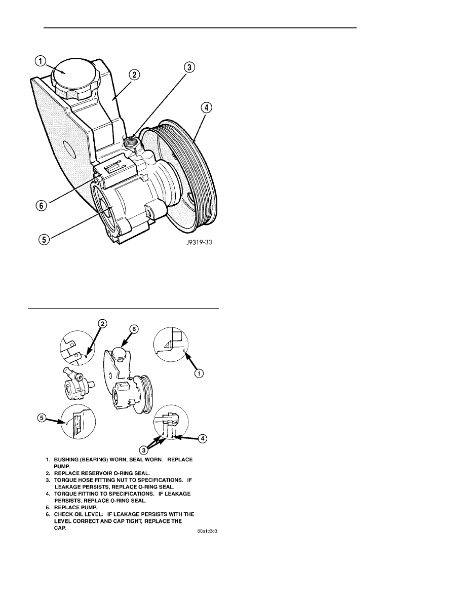
Fig. 1 Pump With Integral Reservoir

1 - CAP
2 - FLUID RESERVOIR (TYPICAL)
3 - HIGH-PRESSURE FITTING
4 - DRIVE PULLEY
5 - PUMP BODY
6 - RESERVOIR CLIP

Fig. 2 Power Steering Pump

TJ

PUMP

19 - 21

PUMP (Continued)

(4) Tighten pump bracket bolt to 57 N·m (42 ft.

lbs.).

(5) Install the pressure line on the pump and

tighten to 28 N·m (21 ft. lbs.).

(6) Install return hoses on pump.
(7) Install drive belt, (Refer to 7 - COOLING/AC-

CESSORY

DRIVE/DRIVE

BELTS

-

INSTALLA-

TION).

(8) Add power steering fluid, refer to Power Steer-

ing Pump Initial Operation. (Refer to 19 - STEER-
ING/PUMP - STANDARD PROCEDURE).

INSTALLATION - 2.4L

(1) Install pulley on pump. (Refer to 19 - STEER-

ING/PUMP/PULLEY - INSTALLATION).

(2) Install pump on the engine mounting bracket.
(3) Tighten pump bracket bolts to 47 N·m (35 ft.

lbs.).

(4) Install 3 pump mounting bolts and tighten to

27 N·m (20 ft. lbs.).

(5) Install the pressure line on the pump and

tighten to 28 N·m (21 ft. lbs.).

(6) Install return hoses on pump.
(7) Install drive belt, (Refer to 7 - COOLING/AC-

CESSORY

DRIVE/DRIVE

BELTS

-

INSTALLA-

TION).

(8) Add power steering fluid, refer to Power Steer-

ing Pump Initial Operation. (Refer to 19 - STEER-
ING/PUMP - STANDARD PROCEDURE).

Fig. 3 Pump Mounting – 4.0L

1 - PUMP ASSEMBLY
2 - PUMP BRACKET

Fig. 4 POWER STEERING GEAR & PUMP - 2.4L

1 - REMOTE RESERVOIR
2 - POWER STEERING PUMP
3 - PUMP MOUNT BRACKET
4 - MOUNTING BOLTS (3)
5 - PRESSURE SWITCH LOCATION
6 - PRESSURE OUTLET HOSE (GEAR TO PUMP)
7 - RETURN HOSE (RESERVOIR TO PUMP)
8 - CLAMPS
9 - STEERING GEAR
10 - INLET HOSE (RESERVOIR TO GEAR)

19 - 22

PUMP

TJ

PUMP (Continued)

SPECIFICATIONS

TORQUE CHART

TORQUE SPECIFICATIONS

DESCRIPTION

N·m

Ft. Lbs.

In. Lbs.

Power Steering Pump

Bracket to Pump

28

21

Power Steering Pump

Bracket to 4.0L Engine

57

42

Power Steering Pump

Bracket to 2.4L Engine

28

21

Power Steering Pump

Flow Control Valve

75

55

Power Steering Pump

Pressure Line

28

21

SPECIAL TOOLS

POWER STEERING PUMP

Analyzer Set, Power Steering Flow/Pressure 6815

Adapters, Power Steering Flow/Pressure Tester

6893

Puller C-4333

Installer, Power Steering Pulley C-4063B

TJ

PUMP

19 - 23

PUMP (Continued)

HOSES

DESCRIPTION

DESCRIPTION - PRESSURE LINE

The hose consists of two metal ends and rubber

center section that contains a tuning cable.

DESCRIPTION - RETURN LINE

Power steering return line is a hose which is

clamped at the pump and the gear.

OPERATION

OPERATION - PRESSURE LINE

Power steering pressure line, is used to transfer

high pressure power steering fluid, from the power
steering pump to the power steering gear.

OPERATION - RETURN LINE

Power steering return line, is used to transfer low

pressure power steering fluid, from the power steer-
ing gear to the power steering pump.

FLUID

DESCRIPTION

The recommended fluid for the power steering sys-

tem is Mopar

t ATF +4.

Mopar

t ATF+4, when new is red in color. The

ATF+4 is dyed red so it can be identified from other
fluids used in the vehicle such as engine oil or anti-
freeze. The red color is not permanent and is not an
indicator of fluid condition, As the vehicle is driven,
the ATF+4 will begin to look darker in color and may
eventually

become

brown.

THIS

IS

NORMAL.

ATF+4 also has a unique odor that may change with
age. Consequently, odor and color cannot be used to
indicate the fluid condition or the need for a fluid
change.

STANDARD PROCEDURE - POWER STEERING
FLUID LEVEL CHECKING

WARNING: FLUID LEVEL SHOULD BE CHECKED
WITH THE ENGINE OFF TO PREVENT PERSONAL
INJURY FROM MOVING PARTS.

CAUTION: MOPAR

T

ATF+4 is to be used in the

power steering system. No other power steering or
automatic transmission fluid is to be used in the
system. Damage may result to the power steering

pump and system if any other fluid is used, and do
not overfill.

The power steering fluid level can be viewed on the

dipstick attached to the filler cap. There are two
ranges listed on the dipstick, COLD and HOT. Before
opening power steering system, wipe the reservoir
filler cap free of dirt and debris. Remove the cap and
check the fluid level on its dipstick. When the fluid is
at normal ambient temperature, approximately 21°C
to 27°C (70°F to 80°F), the fluid level should read
between the minimum and maximum area of the cold
range. When the fluid is hot, fluid level is allowed to
read up to the highest end of the HOT range. Only
add fluid when the vehicle is cold.

Use only Mopar

ATF+4 Do not overfill the

power steering system.

POWER STEERING PRESSURE
SWITCH

DESCRIPTION

A pressure sensing switch (Fig. 5) is included in

the power steering system (mounted on the high-
pressure line). This switch will be used only on vehi-
cles equipped with a 2.4L engine and power steering.

OPERATION

The power steering pressure switch provides an

input to the Powertrain Control Module (PCM). This
input is provided during periods of high pump load
and low engine rpm; such as during parking maneu-
vers. The PCM will then increase the idle speed
through the Idle Air Control (IAC) motor. This is
done to prevent the engine from stalling under the
increased load.

Fig. 5 2.4L POWER STEERING PRESSURE SWITCH

1 - PRESSURE SWITCH
2 - PRESSURE HOSE
3 - POWER STEERING PUMP AND PULLEY ASSEMBLY

19 - 24

PUMP

TJ


Content   ..  474  475  476  477   ..