Jeep Wrangler TJ. Manual - part 254


  Index      Jeep     Jeep Wrangler TJ - service repair manual 2005 year


Search            


Content   ..  252  253  254  255   ..


Jeep Wrangler TJ. Manual - part 254


(6) Install the rotor (Refer to 5 - BRAKES/HY-

DRAULIC/MECHANICAL/ROTORS

-

INSTALLA-

TION).

(7) Install the caliper (Refer to 5 - BRAKES/HY-

DRAULIC/MECHANICAL/DISC BRAKE CALIPERS
- INSTALLATION).

(8) Install the wheel and tire assembly (Refer to 22

- TIRES/WHEELS/WHEELS - STANDARD PROCE-
DURE).

PARKING BRAKE

DESCRIPTION

The parking bake is a hand lever and cable oper-

ated system used to apply the rear brakes.

OPERATION

A hand operated lever in the passenger compart-

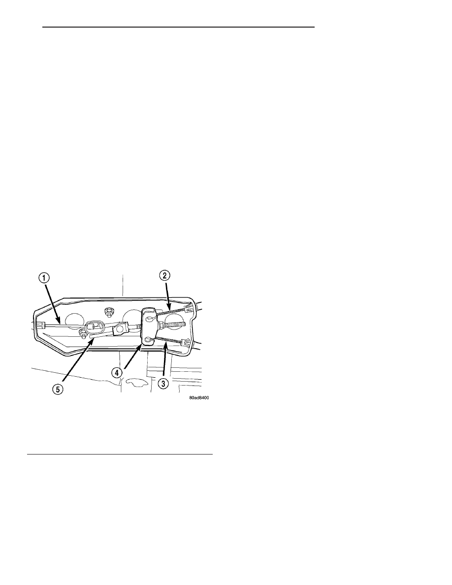
ment is the main application device. The front cable
is connected between the hand lever and the ten-
sioner. The tensioner rod is attached to the equalizer
which is the connecting point for the rear cables (Fig.
60).

The rear cables are connected to the actuating

lever on each secondary brake shoe. The levers are
attached to the brake shoes by a pin either pressed
into, or welded to the lever. A clip is used to secure
the pin in the brake shoe. The pin allows each lever
to pivot independently of the brake shoe.

To apply the parking brakes, the hand lever is

pulled upward. This pulls the rear brake shoe actu-
ating levers forward, by means tensioner and cables.
As the actuating lever is pulled forward, the parking

brake strut (which is connected to both shoes), exerts
a linear force against the primary brake shoe. This
action presses the primary shoe into contact with the
drum. Once the primary shoe contacts the drum,
force is exerted through the strut. This force is trans-
ferred through the strut to the secondary brake shoe
causing it to pivot into the drum as well.

A gear type ratcheting mechanism is used to hold

the lever in an applied position. Parking brake
release is accomplished by the hand lever release
button.

A parking brake switch is mounted on the parking

brake lever and is actuated by movement of the
lever. The switch, which is in circuit with the red
warning light in the dash, will illuminate the warn-
ing light whenever the parking brakes are applied.

Parking brake adjustment is controlled by a cable

tensioner mechanism. The cable tensioner, once
adjusted at the factory, should not need further
adjustment under normal circumstances. Adjustment
may be required if a new tensioner, or cables are
installed, or disconnected.

DIAGNOSIS AND TESTING - PARKING BRAKE

NOTE: Parking brake adjustment is controlled by a
cable tensioner. Once the tensioner is adjusted at
the factory, it should not require further attention.
However, there are two instances when adjustment
will be required. The first is when a new tensioner,
or cables have been installed. And the second, is
when the tensioner and cables are disconnected for
access to other brake components.

The parking brake switch is in circuit with the red

warning lamp in the dash. The switch will cause the
lamp to illuminate only when the parking brakes are
applied. If the lamp remains on after parking brake
release, the switch or wires are faulty, or cable ten-
sioner adjustment is incorrect.

In most cases, the actual cause of an improperly

functioning parking brake (too loose/too tight/won’t
hold), can be traced to a parking brake component.

The leading cause of improper parking brake oper-

ation, is excessive clearance between the parking
brake shoes and the shoe braking surface. Excessive
clearance is a result of lining and/or drum wear,
drum surface machined oversize, or inoperative
adjuster components.

Excessive parking brake lever travel (sometimes

described as a loose lever or too loose condition), is
the result of worn brake shoes, improper brake shoe
adjustment, or improperly assembled brake parts.

A condition where the parking brakes do not hold,

will most probably be due to a wheel brake compo-
nent.

Fig. 60 Parking Brake Components

1 - FRONT CABLE
2 - L.R. CABLE
3 - R.R. CABLE
4 - EQUALIZER
5 - TENSIONER ROD

TJ

BRAKES - BASE

5 - 33

SUPPORT PLATE (Continued)

Items to look for when diagnosing a parking brake

problem, are:

• Rear brake shoe wear.

• Drum surface machined oversize.

• Front cable not secured to lever.

• Rear cable not attached to lever.

• Rear cable seized.

• Brake shoes reversed.

• Parking brake strut not seated in shoes.

• Parking brake lever not seated.

• Parking brake lever bind.

• Adjuster screws seized.

• Adjuster screws reversed.
Parking brake adjustment and parts replacement

procedures are described in the Parking Brake sec-
tion.

SHOES

DESCRIPTION

Drum in hat park brakes are dual shoe, internal

expanding units with an automatic self adjusting
mechanism (Fig. 61).

OPERATION

When the parking brake pedal is depressed the

brake cable pulls the brake shoes outward against

the brake drum. When the brake pedal is released
the return springs attached to the brake shoes pull
the shoes back to there original position.

REMOVAL

(1) Raise and support the vehicle.
(2) Remove the tire and wheel assembly.
(3) Remove the disc brake caliper, (Fig. 62), (Refer

to 5 - BRAKES/HYDRAULIC/MECHANICAL/DISC
BRAKE CALIPERS - REMOVAL).

(4) Remove the disc brake rotor, (Fig. 62), (Refer to

5 - BRAKES/HYDRAULIC/MECHANICAL/ROTORS
- REMOVAL).

(5) Disassemble the rear park brake shoes (Fig.

63).

CLEANING - REAR DRUM IN HAT BRAKE

Clean the individual brake components, including

the support plate exterior, with a water dampened
cloth or with brake cleaner. Do not use any other
cleaning agents. Remove light rust and scale from
the brake shoe contact pads on the support plate
with fine sandpaper.

INSPECTION - REAR DRUM IN HAT BRAKE

As a general rule, riveted brake shoes should be

replaced when worn to within 0.78 mm (1/32 in.) of
the rivet heads. Bonded lining should be replaced
when worn to a thickness of 1.6 mm (1/16 in.).

Examine the lining contact pattern to determine if

the shoes are bent or the drum is tapered. The lining
should exhibit contact across its entire width. Shoes
exhibiting contact only on one side should be
replaced and the drum checked for runout or taper
(Fig. 64).

Fig. 61 BRAKE SHOES

1 - SUPPORT PLATE
2 - PARK BRAKE SHOES
3 - EQUALIZER
4 - SPRINGS
5 - HOLD DOWN CLIPS
6 - ADJUSTER

Fig. 62 PARK BRAKE SHOES INSTALLED

1 - SUPPORT PLATE
2 - PARK BRAKE SHOES
3 - AXLE

5 - 34

BRAKES - BASE

TJ

PARKING BRAKE (Continued)

Inspect the adjuster screw assembly. Replace the

assembly if the star wheel or threads are damaged,
or the components are severely rusted or corroded
(Fig. 64).

Discard the brake springs and retainer components

if worn, distorted or collapsed. Also replace the
springs if a brake drag condition had occurred. Over-
heating will distort and weaken the springs.

Inspect the brake shoe contact pads on the support

plate, replace the support plate if any of the pads are
worn or rusted through. Also replace the plate if it is
bent or distorted (Fig. 64).

INSTALLATION

NOTE: On a new vehicle or after parking brake lin-
ing replacement, it is recommended that the park-
ing brake system be conditioned prior to use. This
is done by making one stop from 25 mph on dry
pavement or concrete using light to moderate force
on the parking brake lever.

(1) Reassemble the rear park brake shoes (Fig. 63).
(2) Adjust the rear brake shoes (Refer to 5 -

BRAKES/PARKING

BRAKE/SHOES

-

ADJUST-

MENTS).

(3) Install the disc brake rotor (Refer to 5 -

BRAKES/HYDRAULIC/MECHANICAL/ROTORS

-

INSTALLATION).

(4) Install the disc brake caliper (Refer to 5 -

BRAKES/HYDRAULIC/MECHANICAL/DISC
BRAKE CALIPERS - INSTALLATION).

(5) Install the tire and wheel assembly (Refer to 22

- TIRES/WHEELS/WHEELS - STANDARD PROCE-
DURE).

(6) Lower the vehicle.

ADJUSTMENTS

ADJUSTMENT - REAR DRUM IN HAT PARK
BRAKE (ROTOR REMOVED)

Under normal circumstances, the only time adjust-

ment is required is when the shoes are replaced,
removed for access to other parts, or when one or
both rotors are replaced.

Adjustment can be made with a standard brake

gauge or with adjusting tool. Adjustment is per-
formed with the complete brake assembly installed
on the backing plate.

CAUTION: Before adjusting the park brake shoes be
sure that the park brake pedal is in the fully
released position. If park brake pedal is not in the
fully released position, the park brake shoes can
not be accurately adjusted.

Fig. 63 BRAKE SHOES

1 - SUPPORT PLATE
2 - PARK BRAKE SHOES
3 - EQUALIZER
4 - SPRINGS
5 - HOLD DOWN CLIPS
6 - ADJUSTER

Fig. 64 BRAKE SHOES

1 - SUPPORT PLATE
2 - PARK BRAKE SHOES
3 - EQUALIZER
4 - SPRINGS
5 - HOLD DOWN CLIPS
6 - ADJUSTER

TJ

BRAKES - BASE

5 - 35

SHOES (Continued)

(1) Raise vehicle.
(2) Remove tire and wheel.
(3) Remove disc brake caliper from caliper adapter

(Refer to 5 - BRAKES/HYDRAULIC/MECHANICAL/
DISC BRAKE CALIPERS - REMOVAL).

(4) Remove rotor from the axleshaft (Refer to 5 -

BRAKES/HYDRAULIC/MECHANICAL/ROTORS

-

REMOVAL).

NOTE: When measuring the brake drum diameter,
the diameter should be measured in the center of
the area in which the park brake shoes contact the
surface of the brake drum.

(5) Using Brake Shoe Gauge, Special Tool C-3919, or

equivalent, accurately measure the inside diameter
of the park brake drum portion of the rotor (Fig. 65).

(6) Using a ruler that reads in 64th of an inch,

accurately read the measurement of the inside diam-
eter of the park brake drum from the special tool
(Fig. 66).

(7) Reduce the inside diameter measurement of

the brake drum that was taken using Special Tool
C-3919 by 1/64 of an inch. Reset Gauge, Brake Shoe,
Special Tool C-3919 or the equivalent used, so that
the outside measurement jaws are set to the reduced
measurement (Fig. 67).

(8) Place Gauge, Brake Shoe, Special Tool C-3919,

or equivalent over the park brake shoes. The special
tool must be located diagonally across at the top of
one shoe and bottom of opposite shoe (widest point)
of the park brake shoes.

(9) Using the star wheel adjuster, adjust the park

brake shoes until the lining on the park brake shoes
just touches the jaws on the special tool.

(10) Repeat step 8 above and measure shoes in

both directions.

(11) Install brake rotor on the axleshaft (Refer to 5

- BRAKES/HYDRAULIC/MECHANICAL/ROTORS -
INSTALLATION).

(12) Rotate rotor to verify that the park brake

shoes are not dragging on the brake drum. If park
brake shoes are dragging, remove rotor and back off
star wheel adjuster one notch and recheck for brake
shoe drag against drum. Continue with the previous
step until brake shoes are not dragging on brake
drum.

(13) Install disc brake caliper on caliper adapter

(Refer to 5 - BRAKES/HYDRAULIC/MECHANICAL/
DISC BRAKE CALIPERS - INSTALLATION).

(14) Install wheel and tire.
(15) Tighten the wheel mounting nuts in the

proper sequence until all nuts are torqued to half the
specified torque. Then repeat the tightening sequence
to the full specified torque of 129 N·m (95 ft. lbs.).

(16) Lower vehicle.

Fig. 65 MEASURING PARK BRAKE DRUM

DIAMETER

Fig. 66 READING PARK BRAKE DRUM DIAMETER

1 - SPECIAL TOOL C-3919
2 - RULER

Fig. 67 SETTING GAUGE TO PARK BRAKE SHOE

MEASUREMENT

1 - RULER
2 - SPECIAL TOOL C-3919

5 - 36

BRAKES - BASE

TJ

SHOES (Continued)


Content   ..  252  253  254  255   ..