Jeep Liberty KJ. Manual - part 298


  Index      Jeep     Jeep Liberty KJ - service repair manual 2006 year


Search            


Content   ..  296  297  298  299   ..


Jeep Liberty KJ. Manual - part 298


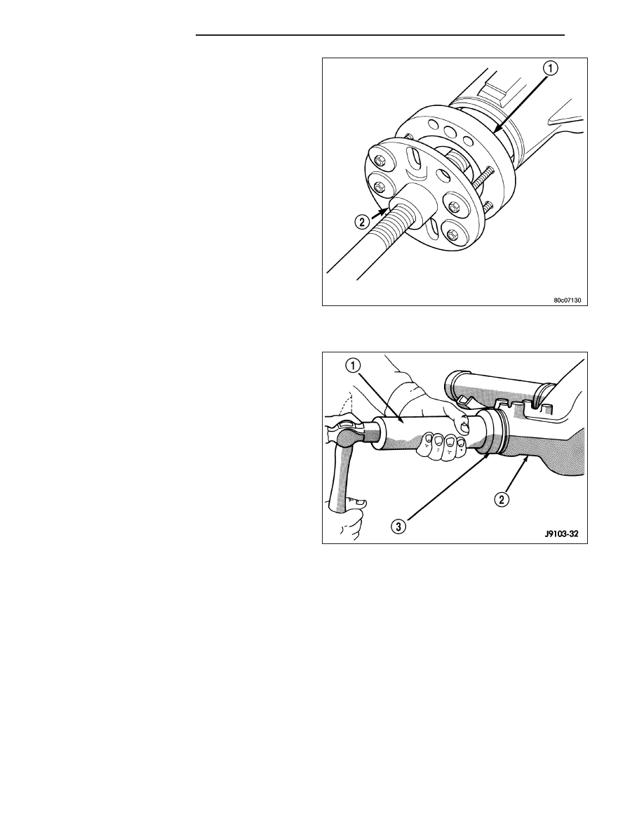
11. Remove companion flange (1) with Puller C-452

(2).

12. Remove pinion seal with a seal puller.

INSTALLATION

1. Apply a light coating of gear lubricant on the lip of

pinion seal.

2. Install new pinion seal with Installer C-4076-B (3)

and Handle C-4735 (1).

3 - 96

REAR AXLE - 8 1/4

KJ

3. Install companion flange on the end of the shaft

with the reference marks aligned.

4. Install bolts into two of the threaded holes in the

companion flange 180 degrees apart.

5. Position Holder 6719A (2) against the companion

flange and install a bolt and washer into one of the
remaining threaded holes. Tighten the bolts so
Holder 6719A is held to the flange.

6. Install companion flange on pinion shaft with

Installer C-3718 and Holder 6719A.

7. Install the pinion washer and a new pinion nut. The

convex side of the washer must face outward.

CAUTION: Do not exceed the minimum tightening
torque

when

installing

the

companion

flange

retaining nut at this point. Failure to heed caution
may result in damage.

8. Hold companion flange with Holder 6719A (2) and

with a torque wrench (3) tighten pinion nut to 285
N·m (210 ft. lbs.). Rotate pinion several revolutions
to ensure the bearing rollers are seated.

9. Rotate pinion (1) with an inch pound torque wrench

(2). Rotating torque should be equal to the reading
recorded during removal plus an additional 0.56
N·m (5 in. lbs.).

CAUTION: Never loosen pinion nut to decrease
pinion bearing rotating torque and never exceed
specified preload torque. Failure to follow these
instructions will result in damage.

10. If rotating torque is low use Holder 6719A to hold

the companion flange and tighten pinion nut in 6.8
N·m (5 ft. lbs.) increments until proper rotating
torque is achieved.

NOTE: The seal replacement is unacceptable if
final pinion nut torque is less than 285 N·m (210 ft.
lbs.).

NOTE: The bearing rotating torque should be con-
stant during a complete revolution of the pinion. If
the rotating torque varies, this indicates a binding
condition.

KJ

REAR AXLE - 8 1/4

3 - 97

11. Install propeller shaft (1) with installation reference

marks (3) aligned.

12. Install rear brake components.

3 - 98

REAR AXLE - 8 1/4

KJ

DIFFERENTIAL

REMOVAL

1. Remove differential fill plug.

2. Remove differential cover and drain lubricant.

3. Remove axle shaft C-locks and axle shafts.

4. Remove ABS sensor from housing.

5. Mark (1) (2) differential housing and bearing caps

(3) for installation reference.

6. Remove bearing adjuster lock bolt (3) from bearing

caps.

7. Loosen differential bearing cap bolts (2).

8. Loosen differential bearing adjusters through the

axle tubes (1) with Adjuster C-4164 (3).

9. Hold differential case while removing bearing caps

and adjusters.

10. Remove differential case and tag differential bear-

ing cups and adjusters to indicate location.

11. Clean housing cavity with flushing oil, light engine

oil or a lint free cloth.

KJ

REAR AXLE - 8 1/4

3 - 99


Content   ..  296  297  298  299   ..