Jeep Grand Cherokee WK. Manual - part 457


  Index      Jeep     Jeep Grand Cherokee WK - service repair manual 2005 year


Search            


Content   ..  455  456  457  458   ..


Jeep Grand Cherokee WK. Manual - part 457


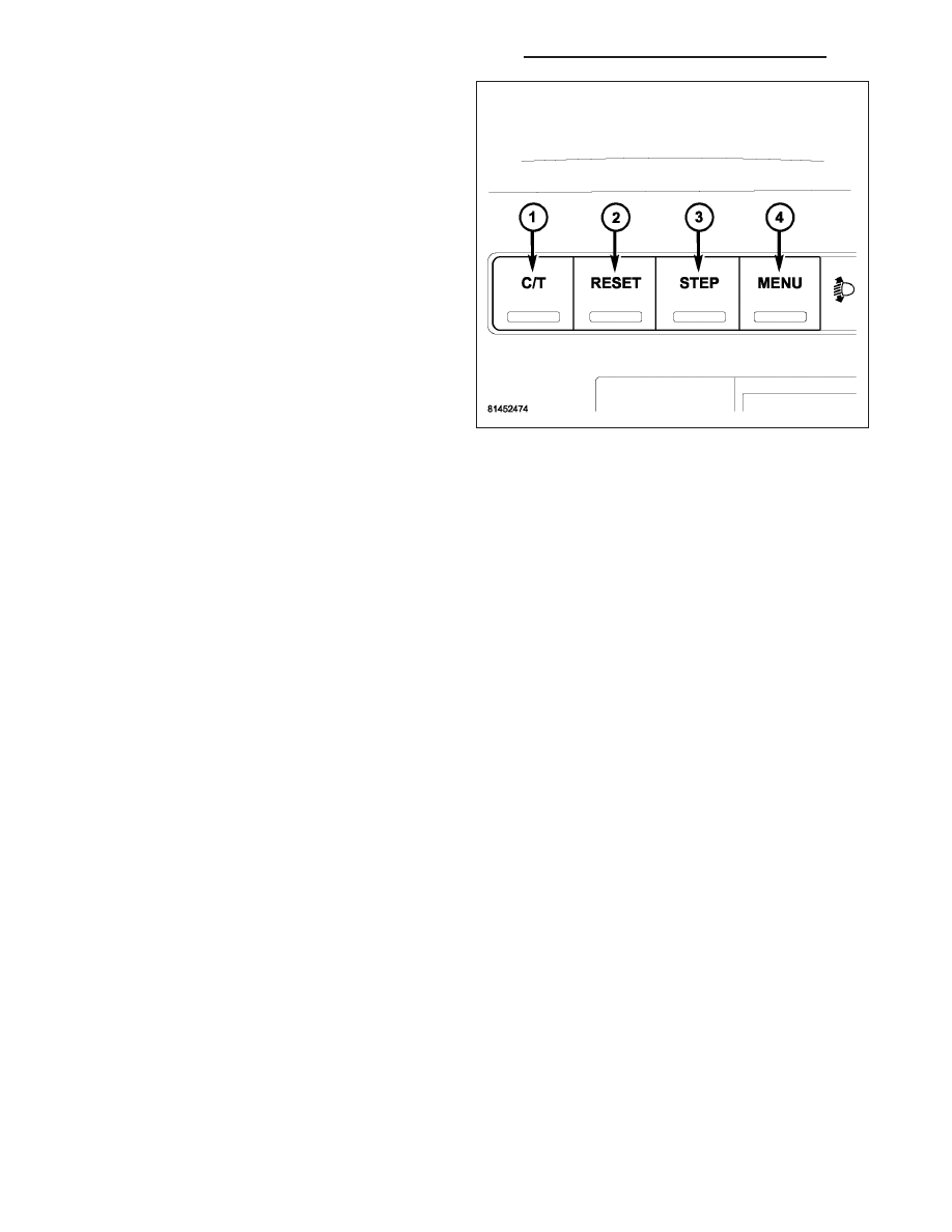
The EVIC control switches are used to operate the dif-
ferent functions of the EVIC system. Pressing and
releasing the MENU button (4) will change the mode
displayed to one of the Personal Settings. The STEP
button (3) is used to make a selection from the Per-
sonal Setting displayed at that time. Pressing and
releasing the C/T (compass/thermometer) button (1)
will cause the EVIC to return to the compass/ther-
mometer/trip computer display mode from any other
mode. From the compass/thermometer/trip computer
display mode the STEP button (3) is used to scroll
through and make selections in the Trip Functions.
Pressing and releasing the RESET button (2) resets
the trip computer screen displayed at that time.

EVIC DISPLAY MODES

SYSTEM STATUS MODE

Displays warnings and user interaction messages. Initial warnings will be displayed accompanied by a series of
audible beeps. Critical text warnings will be displayed until the failure is corrected. Non-critical text warnings will be
displayed for 60 seconds. The driver can scroll to view multiple messages by using the STEP button.

When the appropriate conditions exist, the EVIC displays the following messages:

TURN SIGNAL ON

PERFORM SERVICE

KEY NOT PROGRAMMED - DAMAGED KEY

KEY NOT PROGRAMMED - INVALID KEY

KEY NOT PROGRAMMED - EXCEEDED KEY PROGRAM LIMIT

PROGRAMMING ACTIVE - NEW KEY PROGRAMMED

SERVICE SECURITY KEY

INVALID KEY - TRY ALTERNATE KEY

DRIVER/PASSENGER DOOR OPEN (with graphic)

LEFT/RIGHT REAR DOOR OPEN (with graphic)

X DOORS OPEN (with graphic)

LIFTGATE OPEN (with graphic)

LIFTGATE/DOOR OPEN (with graphic)

LIFTGATE/DOORS OPEN (with graphic)

LIFTGLASS OPEN (with graphic)

HOOD OPEN (with graphic)

HOOD/DOOR OPEN (with graphic)

HOOD/DOORS OPEN (with graphic)

LIFTGATE/HOOD OPEN (with graphic)

HOOD/GLASS/DOOR OPEN (with graphic)

HOOD/GLASS/DOORS OPEN (with graphic)

HOOD/GATE/DOOR OPEN (with graphic)

HOOD/GATE/DOORS OPEN (with graphic)

LIFTGLASS/DOOR OPEN (with graphic)

LIFTGLASS/DOORS OPEN (with graphic)

LIFTGLASS/HOOD OPEN (with graphic)

8M - 18

OVERHEAD CONSOLE - SERVICE INFORMATION

WK

WASHER FLUID LOW (with graphic)

FUEL LOW (with graphic)

CHECK GAUGES

AUTO HIGHBEAM ON

AUTO HIGHBEAM OFF

PARK ASSIST DISABLED

SERVICE PARK ASSIST SYSTEM

TRANSMISSION OVER TEMP

CHECK SHIFT PROCEDURE

SERVICE 4WD SYSTEM

4WD SYSTEM IN NEUTRAL

LOW BRAKE FLUID LEVEL

WARNING! LIMIT SPEED

CHECK GAS CAP

SERVICE SUSPENSION

ESP SYSTEM DISABLED

SERVICE ELEC BRAKE SYSTEM

TRACTION SYS DISABLED

MEMORY #1 POSITIONS SET

MEMORY #2 POSITIONS SET

MEMORY SYSTEM DISABLED - SEATBELT FASTENED (with graphic)

MEMORY SYSTEM DISABLED - VEHICLE NOT IN PARK

DRIVER 1 MEMORY

DRIVER 2 MEMORY

PEDAL ADJUST DISABLED - CRUISE CONTROL SET

PEDAL ADJUST DISABLED - SHIFTER IN REVERSE

SERVICE TIRE PRESS SYSTEM

LEFT FRONT LOW PRESSURE (Premium Tire Pressure Monitoring (TPM) System Only)

RIGHT FRONT LOW PRESSURE (Premium TPM System Only)

LEFT REAR LOW PRESSURE (Premium TPM System Only)

RIGHT REAR LOW PRESSURE (Premium TPM System Only)

SPARE LOW PRESSURE (Premium TPM System Only)

PERSONAL SETTINGS MODE (CUSTOMER PROGRAMMABLE FEATURES)

Allows the driver to set and recall features when the transmission is in Park by pressing and releasing the MENU
button until Personal Settings is displayed in the EVIC. The following personal settings can be set and recalled by
pressing the STEP button:

Language: English, Spanish, German, Italian or French

Display units in English or Metric

Lock doors automatically at 15 mph (24 Kph), On or Off

Unlock door automatically on exit, On or Off

Remote Keyless Entry unlock driver door on first press or unlock all doors on first press

Recall Memory with Remote Keyless Entry Unlock, On or Off

Sound horn with Remote Keyless Entry Lock, On or Off

Flash lights with Remote Keyless Entry Lock, On or Off

Delay turning headlamps off for 0, 30, 60 or 90 seconds

Illuminated approach on for 0, 30, 60 or 90 seconds

Auto headlamp low/high beam, low beam or low/high beam

Headlamps on with wipers, On or Off

Rain Sensing Intermittent Wipers, On or Off

WK

OVERHEAD CONSOLE - SERVICE INFORMATION

8M - 19

Service interval (Gasoline engines), 3200,

{

9600 KM, in increments of 800 KM/2000,...6000 miles in increments

of 500 miles

Service interval (Diesel engines), 4000,...20000 KM, in increments of 1000 KM/2500,

{

12500 miles in incre-

ments of 625 miles

Automatically move seat back on exit, On or Off

Compass/Temperature/Trip Computer Mode

This display provides the outside temperature, one of the eight compass headings to indicate the direction the vehi-
cle is facing, and vehicle trip information. The compass and temperature display is the normal display. When the C/T
button is pressed the compass/temperature display returns.

The trip computer function will be displayed if the STEP button is pressed from the Compass/Temperature display
mode. The trip computer displays the following information:

Average fuel economy

Distance to empty

Trip A

Trip B

Elapsed time

Miles to service

Tire pressure display (if equipped)

Universal Garage Door Transceiver

The Electronic Vehicle Information Center (EVIC) features a driver-interactive display which includes HomeLink sys-
tem messages. For additional information on the universal transceiver (Refer to 8 - ELECTRICAL/OVERHEAD
CONSOLE/UNIVERSAL TRANSMITTER - DESCRIPTION).

DIAGNOSIS AND TESTING

ELECTRONIC VEHICLE INFORMATION CENTER

The Electronic Vehicle Information Center (EVIC) data is obtained from several components on the Controller Area
Network (CAN) Data Bus circuit. The EVIC will not function properly if the bus messages from any of these com-
ponents is not receive. If no EVIC data is displayed, check the CAN Data Bus circuit communications, the Instru-
ment Cluster functions and the Front Control Module (FCM). Any diagnosis of the EVIC system should begin
with, the use of a scan tool and the appropriate diagnostic service information.

The use of a scan tool and the proper diagnostic procedures information are recommended for further testing of the
EVIC and the CAN Data Bus circuit.

For complete circuit diagrams, refer to the appropriate wiring information. The wiring information includes wir-
ing diagrams, proper wire and connector repair procedures, details of wire harness routing and retention, connector
pin-out information and location views for the various wire harness connectors, splices and grounds.

STANDARD PROCEDURE

COMPASS CALIBRATION

CAUTION: Do not place any external magnets, such as magnetic roof mount antennas, in the vicinity of the
compass. Do not use magnetic tools when servicing the overhead console.

The electronic compass unit features a self-calibrating design, which simplifies the calibration procedure. This fea-
ture automatically updates the compass calibration while the vehicle is being driven. This allows the compass unit
to compensate for small changes in the residual magnetism that the vehicle may acquire during normal use. If the
compass readings appear to be erratic or the Electronic Vehicle Information Center (EVIC) displays “CAL”, perform
the following calibration procedure. Also, any time EVIC service replacement components are installed, they must be
calibrated using this procedure. Do not attempt to calibrate the compass near large metal objects such as other
vehicles, large buildings, or bridges; or, near overhead or underground power lines.

8M - 20

OVERHEAD CONSOLE - SERVICE INFORMATION

WK

Calibrate the compass manually as follows:

1. Turn the ignition switch to the On position.

2. Press and release the C/T button (1) so that the

EVIC

display

is

in

the

Compass/Temperature

mode.

3. Depress and hold the C/T push button (1) for

approximately ten seconds. The message “CAL”
will appear in the EVIC display.

4. Drive the vehicle on a level surface, away from

large metal objects and power lines, through one or
twocomplete circles in not less than 16 seconds.
The “CAL” message will disappear from the display
to indicate that the compass is now calibrated.

NOTE: A blank compass display indicates that
vehicle degaussing (demagnetizing) is necessary.

NOTE: If the “CAL” message remains in the dis-
play, either there is excessive magnetism near the compass, or the unit is inoperative. Repeat the calibra-
tion procedure at least one more time.

NOTE: If the wrong direction is still indicated in the compass display, the area selected for calibration may
be too close to a strong magnetic field. Repeat the calibration procedure in another location.

COMPASS DEMAGNETIZING

A degaussing tool (Special Tool 6029) is used to
demagnetize, or degauss, the roof panel above the
overhead console. Equivalent units must be rated as
continuous duty for 110/115 volts and 60 Hz. They
must also have a field strength of over 350 gauss at 7
millimeters (0.25 inch) beyond the tip of the probe.

WK

OVERHEAD CONSOLE - SERVICE INFORMATION

8M - 21


Content   ..  455  456  457  458   ..