Jeep Grand Cherokee WK. Manual - part 1006


  Index      Jeep     Jeep Grand Cherokee WK - service repair manual 2005 year


Search            


Content   ..  1004  1005  1006  1007   ..


Jeep Grand Cherokee WK. Manual - part 1006


P0572-BRAKE SWITCH 1 STUCK ON (CONTINUED)

3.

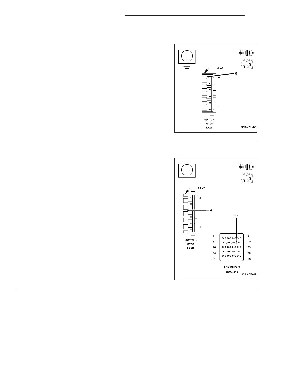
(B15) BRAKE SWITCH NO.1 SIGNAL CIRCUIT SHORTED TO GROUND

Turn the ignition off.

Disconnect the C3 PCM harness connector.

Measure the resistance between ground and the (B15) Brake Switch
No.1 Signal circuit in the Stop Lamp Switch harness connector.

Is the resistance below 100 ohms?

Yes

>> Repair the short to ground in the (B15) Brake Switch No.1

Signal circuit.

Perform the POWERTRAIN VERIFICATION TEST. (Refer
to 9 - ENGINE - STANDARD PROCEDURE)

No

>> Go To 4

4.

(B16) BRAKE SWITCH NO.2 SIGNAL CIRCUIT OPEN

Measure the resistance of the (B16) Brake Switch No.2 Signal circuit
from the Stop Lamp Switch harness connector to the C1 FCM harness
connector.

Is the resistance below 5.0 ohms?

Yes

>> Go To 5

No

>> Repair the open in the (B16) Brake Switch No.2 Signal cir-

cuit.

Perform the POWERTRAIN VERIFICATION TEST. (Refer
to 9 - ENGINE - STANDARD PROCEDURE)

9 - 620

ENGINE ELECTRICAL DIAGNOSTICS

WK

P0572-BRAKE SWITCH 1 STUCK ON (CONTINUED)

5.

PCM

NOTE: Before continuing, check the PCM harness connector terminals for corrosion, damage, or terminal
push out. Repair as necessary.
Using the schematics as a guide, inspect the wire harness and connectors. Pay particular attention to all Power and
Ground circuits.

Were there any problems found?

Yes

>> Repair as necessary.

Perform the POWERTRAIN VERIFICATION TEST. (Refer to 9 - ENGINE - STANDARD PROCEDURE)

No

>> Replace and program the Powertrain Control Module per Service Information.

Perform the POWERTRAIN VERIFICATION TEST. (Refer to 9 - ENGINE - STANDARD PROCEDURE)

WK

ENGINE ELECTRICAL DIAGNOSTICS

9 - 621

P0573-BRAKE SWITCH 1 STUCK OFF

9 - 622

ENGINE ELECTRICAL DIAGNOSTICS

WK

P0573-BRAKE SWITCH 1 STUCK OFF (CONTINUED)

For the Engine circuit diagram (Refer to 9 - ENGINE - SCHEMATICS AND DIAGRAMS).

For a complete wiring diagram Refer to Section 8W.

When Monitored:
Ignition on.

Set Condition:
When the PCM recognizes Brake Switch No.1 is stuck in the high/off position. One Trip Fault. Three good trips
to turn off the MIL.

Possible Causes

(B15) BRAKE SWITCH NO.1 SIGNAL CIRCUIT OPEN

(B16) BRAKE SWITCH NO.2 SIGNAL CIRCUIT SHORTED TO GROUND

(Z904) GROUND CIRCUIT OPEN

STOP LAMP SWITCH

PCM

Always perform the Pre-Diagnostic Troubleshooting procedure before proceeding. (Refer to 9 - ENGINE -
DIAGNOSIS AND TESTING).

Diagnostic Test

1.

ACTIVE DTC

Ignition on, engine not running.

With a scan tool, read DTCs.

Is the DTC active at this time?

Yes

>> Go To 2

No

>> Refer to the INTERMITTENT CONDITION Diagnostic Procedure.

Perform the POWERTRAIN VERIFICATION TEST. (Refer to 9 - ENGINE - STANDARD PROCEDURE)

2.

STOP LAMP SWITCH

Turn the ignition off.

Disconnect the Stop Lamp Switch harness connector.

Measure the resistance between the (Z904) Ground circuit terminal and the (B15) Brake Switch No.1 Signal circuit
terminal in the Stop Lamp Switch.

Apply and release the Stop Lamp Switch while monitoring the ohmmeter.

Does the resistance change from below 5.0 ohms to an open circuit?

Yes

>> Go To 3

No

>> Replace the Stop Lamp Switch.

Perform the POWERTRAIN VERIFICATION TEST. (Refer to 9 - ENGINE - STANDARD PROCEDURE)

WK

ENGINE ELECTRICAL DIAGNOSTICS

9 - 623


Content   ..  1004  1005  1006  1007   ..