Content .. 1002 1003 1004 1005 ..
Jeep Grand Cherokee WK. Manual - part 1004
P0563-BATTERY VOLTAGE HIGH (CONTINUED)
2.
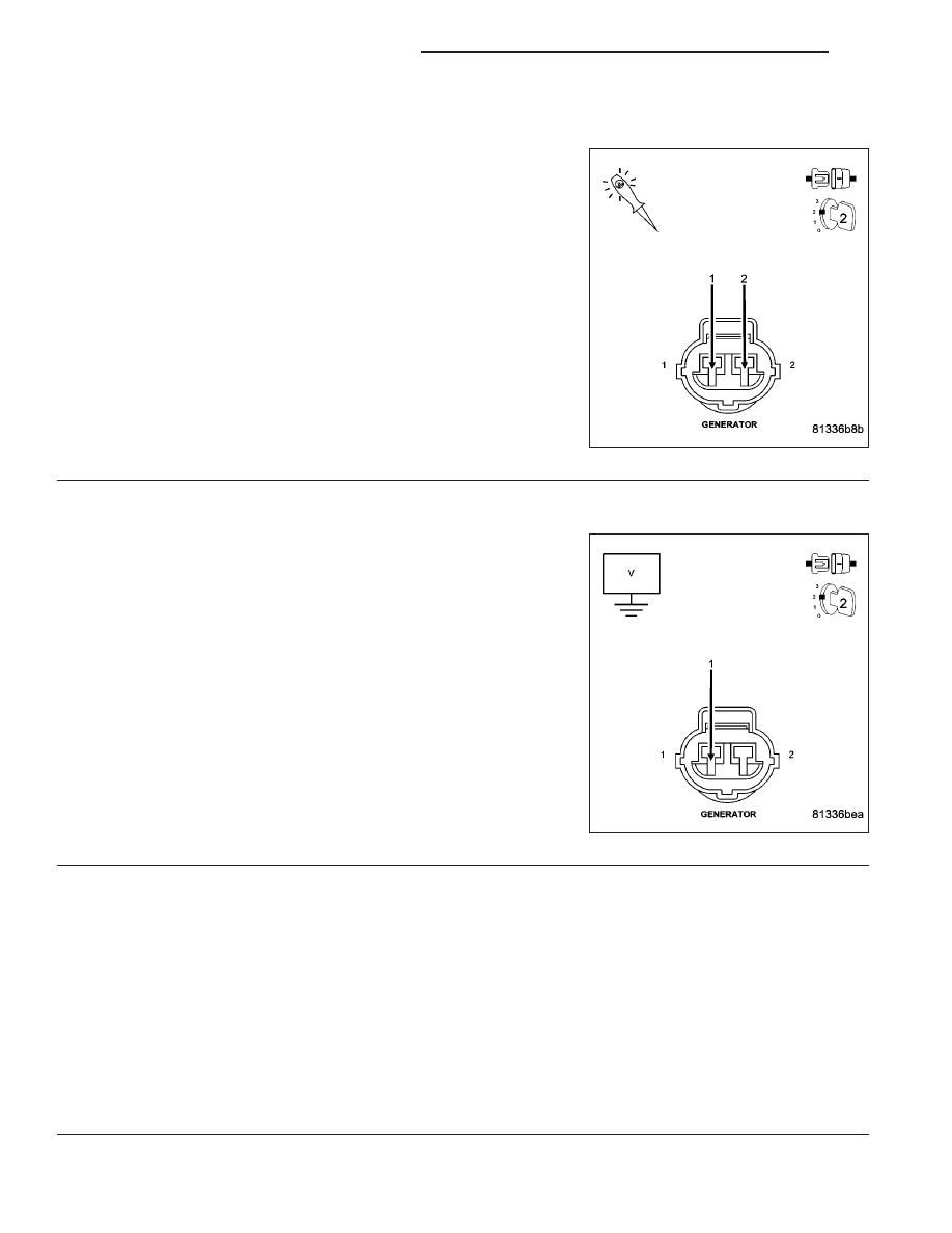
GENERATOR OPERATION
Turn the ignition off.
Disconnect the Generator Field harness connector.
Using a 12-volt test light, jump across the Generator Field harness
connector.
Ignition on, engine not running.
With the scan tool, actuate the Generator Field Driver.
Does the test light illuminate brightly and flash on and off?
Yes
>> Replace the Generator.
Perform the POWERTRAIN VERIFICATION TEST. (Refer
to 9 - ENGINE - STANDARD PROCEDURE)
No
>> Go To 3
3.
(K125) FIELD CIRCUIT SHORTED BATTERY VOLTAGE
Turn the ignition off.
Disconnect the C2 PCM harness connector.
Ignition on, engine not running.
Measure the voltage on the (K125) Gen Field Control circuit at the
Generator Field harness connector.
Is the voltage above 1.0 volt?
Yes
>> Repair the short to battery voltage in the (K125) Gen Field
Control circuit.
Perform the POWERTRAIN VERIFICATION TEST. (Refer
to 9 - ENGINE - STANDARD PROCEDURE)
No
>> Go To 4
4.
PCM
NOTE: Before continuing, check the PCM harness connector terminals for corrosion, damage, or terminal
push out. Repair as necessary.
Using the schematics as a guide, inspect the wire harness and connectors. Pay particular attention to all Power and
Ground circuits.
Were there any problems found?
Yes
>> Repair as necessary.
Perform the POWERTRAIN VERIFICATION TEST. (Refer to 9 - ENGINE - STANDARD PROCEDURE)
No
>> Replace and program the Powertrain Control Module per Service Information.
Perform the POWERTRAIN VERIFICATION TEST. (Refer to 9 - ENGINE - STANDARD PROCEDURE)
9 - 612
ENGINE ELECTRICAL DIAGNOSTICS
WK