Engine Iveco C10/C13/C78/Cursor 13/Cursor 78. Manual - part 127
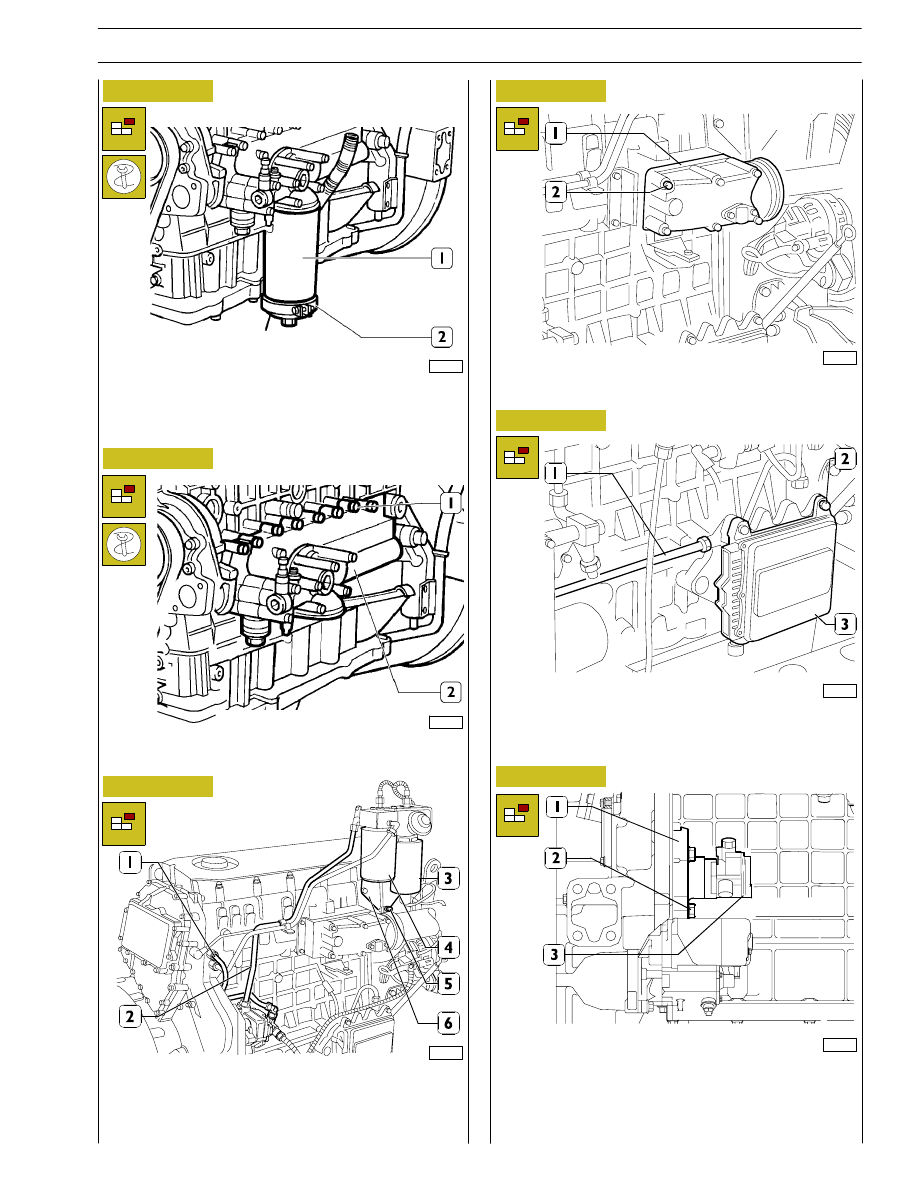
Figure 10
Figure 11
Figure 12
Figure 13
Figure 14
Unscrew the oil filter (1) by tool 99360314 (2).
Unscrew the screws (1) and remove the entire heat
exchanger (2).
Take out the screws (2) and remove the intake manifold (1).
107940
107941
107942
Disconnect fuel lines (1) from cylinder head; (2) and supply
pump.
Remove screws (5) and support (6) complete with fuel filter
(3) and sedimentation filter (4).
107943
107944
Disconnect fuel line (1) from central unit (3).
Remove screws (2) and disconnect central unit (3).
Remove screws (2) and disconnect power takeoff (1)
complete with supply pump (3).
To go on with the engine disassembly as described for the
industrial/agricultural applications engines.
Figure 15
107945
SECTION 2 - APPLICATION G-DRIVE
25