Engine Iveco C10/C13/C78/Cursor 13/Cursor 78. Manual - part 108


  Index      Iveco     Engine Iveco C10/C13/C78/Cursor 13/Cursor 78 - service repair manual 2006 year


Search            


Content   ..  106  107  108  109   ..


Engine Iveco C10/C13/C78/Cursor 13/Cursor 78. Manual - part 108


Checking head bearing surface on cylinder
block

Mount the connecting rod caps (1) together with the bearing
shells. Tighten the screws (2) fixing the connecting rod caps
to a torque of 60 Nm (6 kgm). Using tool 99395216 (3),
further tighten the screws with an angle of 60

°.

47594

47583

36159

Figure 73

Figure 74

Figure 75

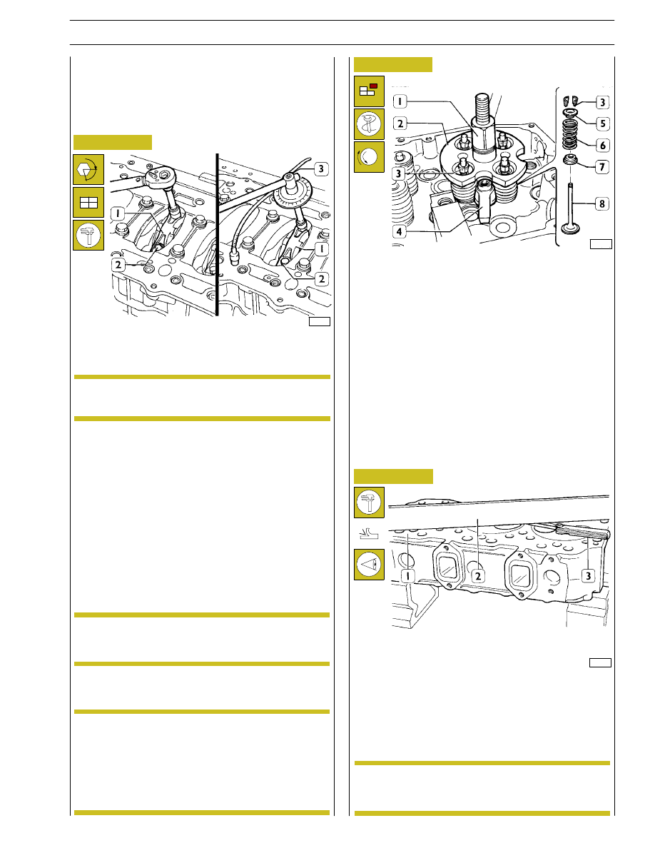
Mount and secure the tool 99360263 (2) with the bracket
(4). Screw down with the device 99360261 (1) to be able to
remove the cotters (3). Take out the tool (2) and extract the
top plate (5), spring (6) and bottom plate (7).
Repeat this process on all the valves.
Turn over the cylinder head and take out the valves (8).

Check the supporting surface (1) of the head on the cylinder
block with a rule (2) and a feeler gauge (3). If you find any
deformation, level the head on a surface grinder; maximum
amount of material that can be removed 0.2 mm.

Checking crankpin assembly
clearance

To measure the clearance, carry out the following
operations.
Connect the connecting rods to the relevant journals of the
crankshaft, placing a length of calibrated wire on the journals.

α

(Demonstration)

After this process, you need to check the valve
recessing and injector protrusion.

Remove the caps and determine the clearance by comparing
the width of the calibrated wire with the graduated scale on
the case containing the calibrated wire.
Upon final assembly: check the diameter of the thread of the
screws (2), it must be no less than 13.4 mm; if it is, change the
screw. Lubricate the crankpins and connecting rod bearings.
Tighten the screws (2) as described above.

The thread of the screws (2), before assembly, has
to be lubricated with engine oil.

NOTE

CYLINDER HEAD

Before dismounting cylinder head, check cylinder head for
hydraulic seal by proper tooling; in case of leaks not caused
by cup plugs or threaded plugs, replace cylinder head.

In case of plugs dismounting/replacement, on
mounting, apply sealant Loctite 270 on plugs.

NOTE

Dismounting the valves

Before dismounting cylinder head valves, number
them in view of their remounting in the position
observed on dismounting should they not have to
be overhauled or replaced.

NOTE

NOTE

SECTION 4 - OVERHAUL AND TECHNICAL SPECIFICATIONS

37

MAIN DATA OF VALVES AND VALVE GUIDES

* Measurement to be made after driving in the valve guides

71718

73555

Figure 76

Figure 77

Check with a micrometer that the diameter of the valve
stems is as indicated. If necessary, grind the valve seats with
a grinding machine, removing as little material as possible.

1

2

MAIN DATA OF VALVE SEATS

1. Intake valve seat — 2. Exhaust valve seat

The valve seats are reground whenever the valves
or valve guides are ground and replaced.

Valve seats

Regrinding — replacing valve seats

NOTE

48625

Valves

Decarbonizing and checking valves

Remove the carbon deposits on the valves with a wire brush.
Check that the valves show no signs of seizure or cracking
and check with a micrometer that the valve stem diameter
comes within the required values (see Figure 77); replace the
valves if it does not.

Figure 78

38

SECTION 4 - OVERHAUL AND TECHNICAL SPECIFICATIONS

Figure 79

41032

Check the valve seats (2). If you find any slight scoring or
burns, regrind them with tool 99305019 (1) according to the
angles shown in Figure 78. If it is necessary to replace them,
using the same tool and taking care not to affect the cylinder
head, remove as much material as possible from the valve
seats so that, with a punch, it is possible to extract them from
the cylinder head.

Heat the cylinder head to 80

÷ 100°C and, using a drift, fit

in the new valve seats (2), chilled beforehand in liquid
nitrogen. Using tool 99305019 (1), regrind the valve seats
according to the angles shown in Figure 78.

After regrinding the valve seats, using tool 99370415 and dial
gauge 99395603, check that the position of the valves in
relation to the plane of the cylinder head is:

- -0.45

÷ -0.75 mm (recessing) intake valves

- -1.65

÷ -1.95 mm (recessing) exhaust valves.

71719

Figure 80

Checking clearance between valve-stem and
associated valve guide

Using a dial gauge with a magnetic base, check the clearance
between the valve stem and the associated guide. If the
clearance is too great, change the valve and, if necessary, the
valve guide.

Valve guides

Replacing valve guides

The valve guides are removed with the drift 99360143.
They are fitted with the drift 99360143 equipped with part
99360296.

Part 99360296 determines the exact position of assembly of
the valve guides in the cylinder head. If they are not available,
you need to drive the valve guides into the cylinder head so
they protrude by 30.8

÷31.2 mm.

After driving in the valve guides, rebore their holes with the
smoother 99390330.

Figure 81

Replacing injector cases

Removal

60619

To replace the injector case (2), proceed as follows:

- Thread the case (2) with tool 99390804 (1).

The steps described in Figs. 81 - 84 - 85 - 86 need to be
carried out by fixing the tools, with the bracket A, to the
cylinder head.

SECTION 4 - OVERHAUL AND TECHNICAL SPECIFICATIONS

39

60621

- Using the tool 99390772 (2) remove any residues (1) left

in the groove of the cylinder head.

- Screw the extractor 99342149 (2) into the case (3).

Screw down the nut (1) and take the case out of the
cylinder head.

60620

60622

- Lubricate the seals (3) and fit them on the case (4). Using

tool 99365056 (2) secured to the cylinder head with
bracket A, drive in the new case, screwing down the
screw (1) upsetting the bottom portion of the case.

60623

- Using the reamer 99394041 (1-2), rebore the hole in the

case (3).

Figure 82

Figure 83

Figure 84

Figure 85

Assembly

40

SECTION 4 - OVERHAUL AND TECHNICAL SPECIFICATIONS


Content   ..  106  107  108  109   ..